Presence Mode with Photocell:
On movement the light will be turned ON when ambient light level
is below Setpoint On lux level. If no presence is detected, light will
be turned off after Time Out Period. If a presence is detected, light
will continue ON.
In this mode the detector can be overridden on (off) by use of the
remote control, it will remain on (off) for that period of occupancy.
A new programming command will cancel the override.
During programming the sensor will switch the lights ON or OFF
(depending on current state) for 2 seconds to acknowledge a
successful programming operation.
Set the dil switches to the following positions to achieve the desired
modes, point at the OSFM/P or OSSM/P and press the button.
Introduction
Occupancy Sensor - OSFM/P, OSSM/P
Hand Held Controller - OSRC, OSRCP
Congratulations on purchasing your new Klik Occupancy sensor
and/or hand held controller.
This product must be installed by a competent person in accordance
with the current editions of the IEE Wiring Regulations (BS7671) and
Building Regulations.
The Klik occupancy sensor responds automatically to presence and
ambient light conditions to provide a quick and efficient means of
lighting control.
The OSFM/P and OSSM/P use passive infrared technology and
combine an integral photocell to provide automatic control of light-
ing. Programming is achieved using the hand held remote control
(OSRCP), which enables easy commissioning when you have
multiple sensors, saving time during installation.
The time delay and lux levels can be adjusted using the hand held
programmer, without the need to even touch the sensor.
Positioning Considerations
The OSFM/P and OSSM/P should be mounted in the centre of the
group of luminaires to be controlled and the optimum all round cov-
erage is achieved with the unit mounted at a height of 2.5m. The
coverage for these sensors at this height is 6m diameter.
For Technical Support regarding this product please phone:
0870 607 6677
Installation and Mounting: OSSM/P Surface Mounted Version
OSSM/P is suitable for surface mounting. The product can be
directly mounted onto a BESA box or to any solid surface using the
fixing positions.
1. Decide upon the position for mounting the occupancy sensor.
2. Remove the top cover of the sensor by twisting the top cover
anti-clockwise.
3. Fix the ceiling-mounting bracket using the two screws provided.
4. Connect the cables to the corresponding terminals on the base
cover assembly. (see page 2 for connection diagrams)
5. Position the base cover assembly over the ceiling-mounting
bracket and rotate.
Note: Thi product can be in talled without the need for the ceiling
mounting bracket if there i no BESA box.
Modes of Operation
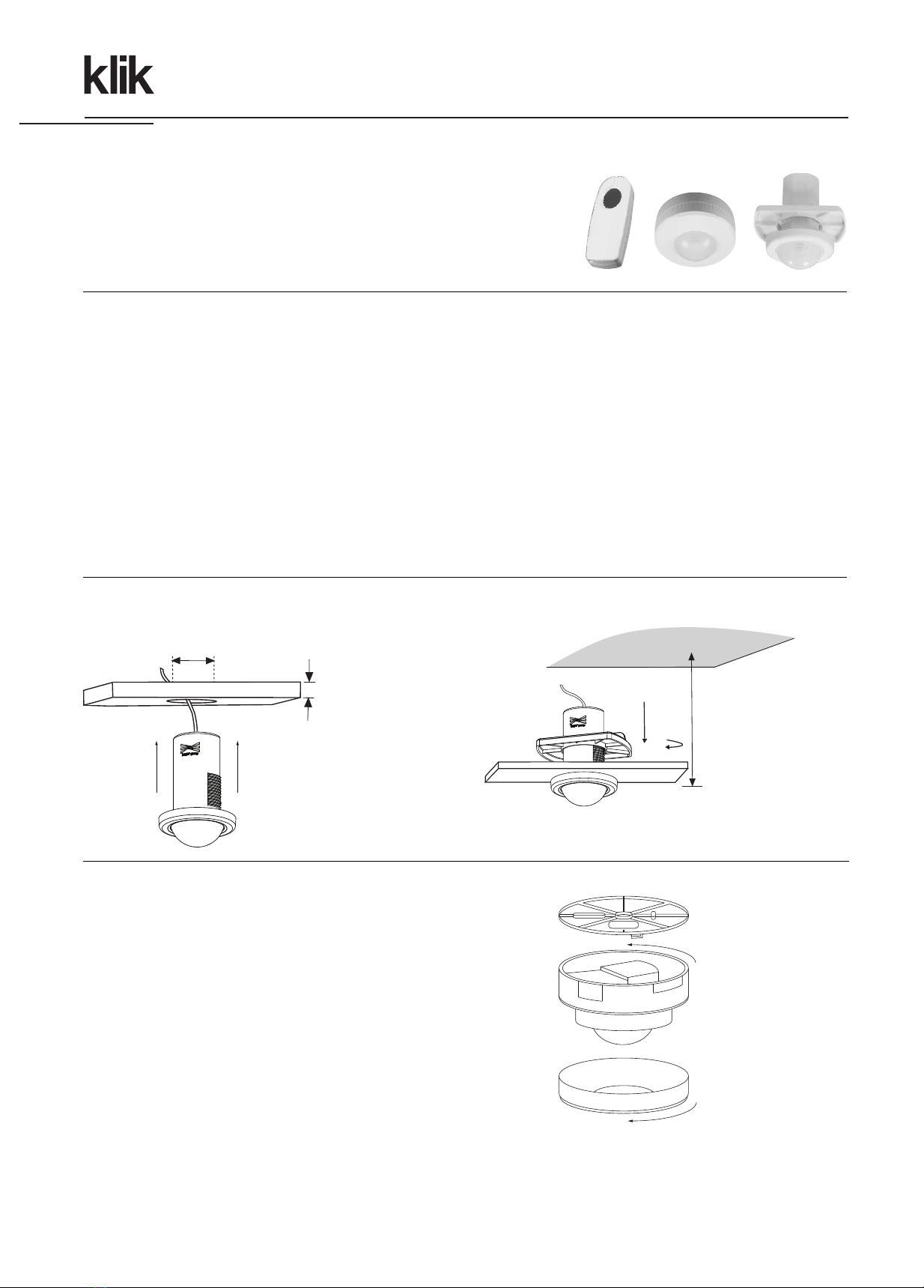
Installation and Mounting: OSFM/P Flush Mounted Version
Minimum
125 mm
Maximum
35mm
Secure with locking ring
before terminating the
cable into the KLDS,
junction Box or Luminaire.
Cut 50mm
circular hole
Ensure there is sufficient
cable length to reach from
the chosen location to the
LDS box, unction box or
Luminaire tray.
Close
Presence Detection Mode:
On movement the light will turn ON and remain on whilst presence is
detected. If no presence is detected, light will be turned off after
Time Out Period. This mode is independent of the photocell and
lighting levels.
In this mode the detector can be overridden on (off) by use of the
remote control, it will remain on (off) for that period of occupancy.
A new programming command will cancel the override.
alk Test Mode:
On movement the light will turn on, and off after 5 seconds if no
movement has been detected. This mode should be selected during
commissioning stage to verify the operation of the sensor.
Factory Reset:
This will reset the sensors settings to the default factory settings.
- Timeout = 24 min
- Normal Mode
Hager Ltd. Hortonwood 50, Telford, Shropshire, TF1 7FT
Sales Hotline: 0870 240 2400
Technical Support Helpline: 0870 607 6677
Modify Parameters:
Setting Time Out Period:
Set the switch positions according to the time delay period
required.
i.e. 36 minutes = 24 + 12
9 minutes = 6 + 3
After this time period if no presence is detected the lights will go
off.
14
Ceiling mounting
bracket
Base cover assembly
Top cover
For normal operation For presence detection only
For commissioning and testing
Open
Possible Modes of Operation:
Normal Mode
Presence Detection Only
Walk Test Mode
Default to Factory Settings
www.hager.co.uk
4696016 v5
Setting Set Point On:
Wait for, or simulate a lux level at which the lighting should switch
on. (Note: the lights should be switched off before programming
this setting) Aim programmer at sensor and push button.
NB: After modifying any parameters return the dil switches to the
desired mode of operation.


