Klugmann KH9850 User manual

KH9850
Hood
INSTRUCTION MANUAL
Klugmann Hausgeraete GmbH.
Gropiusstraße 7,
48163 Münster, Deutschland
+49 (0)2501 - 963 5732
+49 (0)2501 - 963 1834
service@klugmann-hausgeraete.de
www.klugmann-hausgeraete.de

EN
*This product is designed to be used
*Operational power supply is AC 220-
240 Volts 50Hz.
*Your product has the earthed plug
cable.This cable must be connected
to AC power supply which is fully
*All electrical wiring must be done by
a qualified electrician.
*Unauthorized installation can be work
in poor performance and damage to the
product and lead to accidents.
*Make sure the power cable is not
pinched and not crushed to during
installation. The power supply cable
must not pass near the stove.
It may be melting and cause a fire.
*Do not connect the unit to the power
supply unless the assembly of the
*In case of any danger,power off the
product easly accessible to ensure that
your plug.
*Do not touch the illumination lamps of
the device when they are used for
a long time.
*Hoods are made for home use while
cooking. If used for other purposes,
there is a risk of malfunction and
interests outside of warranty.
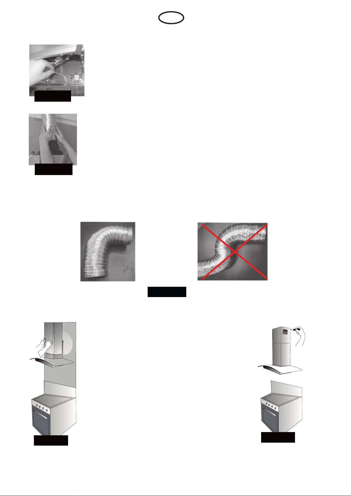
*About the evacuation of the outlet air,
Please follow the rules and guidelines
of the authorities.
WARNINGS AND SAFETY PRECAUTIONS
*Flammable foods should not be cooked
under this device.
*Operate the Hood Fume after placing
the casserole and pan on the cooker.
Otherwise, in some parts of the device
may result deformed due to high
temperature.
*Out of the stove pots,pans and so on.
Turn off the stove before.
*Do not leave hot oil on the stove.
Spontaneously flammable in containers
with hot oil.
*Please be careful. Roast type, etc..
While food oils can ignite and cause fire
damage.
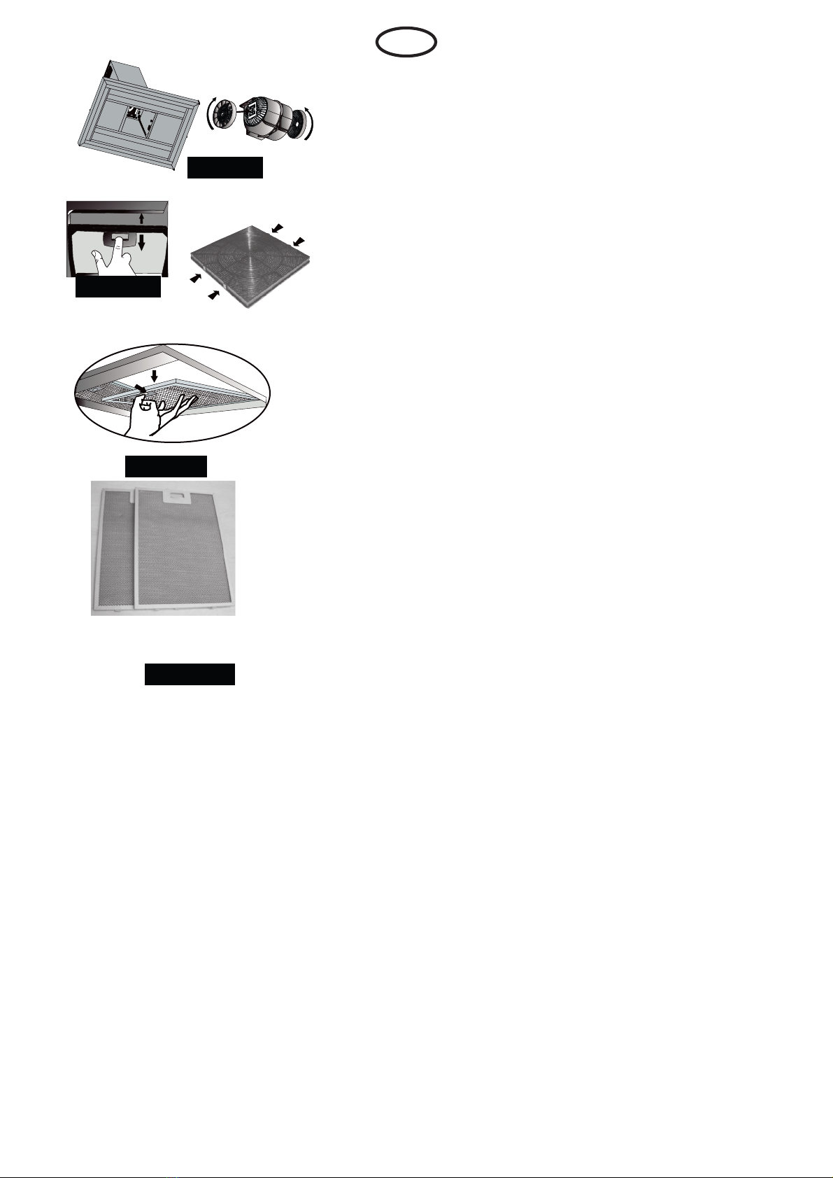
*Ensure the timely replacement or cleaning
of the filters.Accumulated on the filter is
a risk of fire due to the oil.
*Only use the metal filter provided with
the device and do not use other materials
*Do not operate the device without it’s filter.
Do not remove the metal filter of the device
while it is operating.
*In case of flare begin, turn off energy of
hoods and cookers.
*The cleaning of the device should be
implemented with periodic intervals.
*Turn off your device before maintenance
at home
grounded.
device is fully completed.
to replace it.
operations.
2

*Electric hood and supplied with energy
other than electricity devices running at
the same time negative pressure in
the room 4 Pa ( 4 X 10 bars ) must not
exceed.
*Do not any connection to chimneys which
the stoves are connected, waste gasses
are exhausted or to chimneys which have
uprisings of the flames.
*When your product is 150mm or 120mm
diameter chimney connector pipe use.
The piping as short as possible and should
be less angled.
*Make sure your child play with the
product. Do not allow children to use the
product.
For your safety, extractor fan installation (max. of 6 Amp) fuse use.
*As the packing materials of the device
may be harmful to children, keep them
out of reach of the children.
*Supply cord is damaged, in order to
avoid a dangerous situation, the
manufacturer or service or be replaced
by a qualified person equally.
*Accessible part of the cooking appliance
may be hot when running.
*All materials used in the packaging of your product which is suitable for recycling.
*Parcels during transport, the signs mentioned above must be followed.
*To move your product box located on the side of the lift grips Hand Piece.
If you need transportation;
*Please keep the original packaging.
*Move with the original packaging, handling marks on the packaging must be observed.
If there is no original package;
*Do not put weight on the device.
*Protect the outer surface of the blow.
DDaammaaggee ttoo tthhee pprroodduucctt bbyy ppaacckkaaggiinngg yyoouurr mmoovvee..
EN
*In case of flare begin, turn off energy of
hoods and cookers. Cover the top of the
flame. Never use water to extinguish..
Shipping and Handling Precautions regarding.
3

Standard Accessories
Plastic adapter (Ø150mm/120mm)
Plastic adapter that plugs into the air outlet of the hood.
Picture-1
Device Location:
Upon completion of the installation of hoods,
electric stove of the product should be a minimum
distance of 65 cm. Gas and other fuel-fired
furnaces, the minimum distance between the
Unpacking the device:
* Please check whether your device has a deformation.
* Shipping failures should be reported immediately to the shipping charge.
* Showing errors also must be notified to the seller.
*Do not allow children to play with packaging material !!!
Min.55 cm
Min.65 cm
Picture 1
Figurel 1
HOOD ASSEMBLY
Metal bracket to mount the hood:
Items to hang on the wall has the (L) form 2 pieces metal
bracket to mount.This sheet with set screws for ease of
packing is given. Product before you hang this sheet is
located on the cabinet with M5 screw fastening nuts and
bolts M5x10. Picture-2
Picture 2
M5x10
M4x20
EN
product should be 75cm. Figure-1
4

Be nailed to the wall dowels
8 mm dowels for hanging screws (A, B, C) into the holes you
drilled. To connect the chimney mounting plate. 7 mm 2 pieces
dowels into the holes you drilled with the Ø7mm. Picture-3
Chimney mounting bracket on the wall where you place (Ø7) to
dowels, 3,9 x22 with a screw mount.
Picture-4
Picture 3
Picture 4
The wall that you have age 8 mm dowel (A, B) hanger screws,
screw with 5x50. 5 mm distance between the screw head and
the wall must remain. Picture-5
Resim 6
AABB
Picture 5
Hang on the wall of the cooker hood:
Hold the body of the hood. Previously that
connect the hood to cabinet (L) in the form
of sheets hang from points A and B on
the wall. Figure-2
After finished Hanging, mounted on
the wall in Picture-6 tighten the screws.
you can see the delicate balance settings
to Picture-7
Figure 2
Body Holder (L)
Horizontal Positioning
M5x10
Wall fixing part
M4x20
Ø8
5x50
Picture 7
Resim 6
Picture 6
Screwing Hanger Bracket:
The age of the wall that you have to Ø 8 mm dowel
screw mounts and set the measure. 5mm distance between
the screw head and the wall must remain. Picture-6
EN
Hanger of the screws to be screwed
Vertical Positioning
5

Resim 10
Picture 8
After you have installed instead of the hood.Fixing hood body
center hole (C) with a screw to wall.
Picture-8
Picture 9
Aluminum pipe fitting
Insert the aluminium pipe on the plastic adapter. The other end
of the tube into the hole in the wall chimney insert it. Picture-9
Aluminum pipe elbows and bends should be less. Picture-10
True False
Picture 10
Chimneys place it on the hood body. Figure-3
the wall mounting plate which is fixed to the
screw. Figure-4
Figure 3 Figure 4
EN
Internal chimney, chimney top outer edge of
6

Figure 5
Note: Lamps are available from Authorized Services.
Device Functions
Hoods use chimney or without chimney in the kitchen.
In use with chimney;
Hoods must be connected to a chimney to expel air.
chimney hoods to get the best performance from the shortest path to the pipe system
to track the note. The device stands out as being suitable for use from the factory with
a chimney.
Warning!!!
Hoods output; where the smoke duct must not be connected to the other.
Picture 11
Aktive Carbon filter
For environments without a chimney from the indoor air by
filtration activated carbon filter to be used indoors again. Aktive
Carbon filters should be obtained from your dealer, or service.
Picture-11
Replacement of lamps
Disconnect the hood from the electricity. Remove aluminium filter.
Replacing halogen lamp
Figure-5
Figure 6
Light Bulp
Take over the bulp by turning it counterclockwise. Replace with new of
the same value bulp by turning it clockwise.Figure-6
Carefully remove the faulty bulb.Replace with new of the same value.
(Lamps while hot can burn your hand. Allow to cool.)
Whether or not use carbon filters in each case used oil filters must be installed in the product.
Do not use your product unfiltered oil. Disconnect the hood from the electricity and replace with
new carbon filter. Carbon filters should be replaced with 3-5 month intervals.
Carbon filters should not be washed in no time.
EN
Remove the metal filters.Push the lamp from the rear side
as shown in the picture (A) . And take off by turning the lamp(B).
7
PowerLed Spot Changing
Figure 5
Change of LED Lamps
Disconnect the electrical connection of the hood.
Remove the faulty led lamp by pulling as shown in Figure 6.1-2
Get it separated from the cable connector and insert the equivalent
led lamps provided from the service and make the electrical connection
by plugging into the socket. Tighten the spring on the edge of the lamp.
To avoid the possibility of an electric shock, please make sure that the device circuit is open
before replacing the lamp.
Warning: Figure 6.1-2

Figure 7
Figure 7a
Circular Carbon Filter Changing
Products used in the two carbon filters
To replace the carbon filter, motor cover with carbon
filter on the channel on the channels align and turn it
clockwise. Remove to carbon filter by turning it
counterclockwise. Figure-7
Square Carbon Filter Changing
To remove the carbon filter pressing of the upper latch
and pull it toward you.
Maintenance
Disconnect the hood from the electricity to maintenance or
*
cleaning.
Aluminium cassette filters the amount of airborne dust
*
and oils.
*Metal filter must be washed in hot soapy water every month or
if possible in the dishwasher (60°C)
Press on the spring clamps at the tip of cassette filter
*
and disassemble.
Do not assemble before drying after
cleaning. Figure-8 and Picture-12
Outer surfaces of your extractor must be wiped by a cloth
*
wet with liquid detergent.
Electronic components must not come into contact with
*
water or other substances.
Inox products use the appropriate cleaning and
*
maintenance materials. This will extend the life of the
device.
Warning:
Aluminium filters are dishwasher safe. Aluminum filter
discolour after a few washes. This is a normal condition.
Does not require modification of the filters.
Washable Aluminium
cassette filters
Picture 12
Figure 8
Efficient Ventilation
For correct ventilation , windows opening outside must be kept closed.Doors and
windows opening to other rooms may be kept openAfter the cooking process .
equipment in working order leave for a while, so the rest will be absorbed odors and
vapors.
IMPORTANT NOTE:
This advice does not apply to operations without chimney.
EN
Figure-7a
Pay attention when operating extractor simultaneously with devices running by
using the ambient air with fuel (such as heaters operating gas, diesel fuels, coal or
firewood, geyser etc.) because it may affect burning since extractor discharges the
air to outside.
8

Using the Hoods
The Control Panel
The control panel is in the front of the device.
Here the device is comfortable to use and can
be done easily.
Device selection stage
On/Off Minus Display Plus On/Off
Lighting
Timer
The speed of the device can be changed by the process. Evaporation in a process of intense speed should
be increasedat least that should be reduced in the process. The important thing about this device is operated
in conjunction with a stove. The resulting balanced airflow will positively affect traction device. After finishing
device is recommended to run a few more minutes.The automatic shutdown system can be used for this
operation.
Use of Electronic Keys
a) Motor On/Off:
It can be used for opening and closing the engine. At the begining engine start with second speed.
b) Speed Selection:
V - (Negative) : It can be used to lower speed of engine to the first speed. When the button is pushed as
continual speed of engine is become less. And when the button is pushed one time speed of engine
decreases one time.
V + (Positive) : It can be used to increase speed of engine to the highest period. When the button is
pushed as continual speed of engine is become to rise continiously. And when the button is pushed one
by one speed of engine increasees one by one.
c) Automatic Shutdown (Timer):
If the timer button is pushed while the engine is running, speed button will start to flash than 15 minutes
later engine and lamp will be closed. If the timer buttn is pushed again the flash stops and timer will be
canceled.
d) Lighting On/Off:
It can be used for opening and closing the lamp.
e) Filter Alerts:
After working on the device display a specific expression that metal filters must be cleaned (C) warning
appears.After the filter has been cleaned and replaced the engine on / off button for 5 seconds. hold.
Before (C) and then (E) notice appears. At the end of this process, the filter will be reset warning.
EN
9

USING INFORMATION:
· M.On/Off Button: It is using for opening and the motor. At the beginning motor starts with
· –
(minus) Button: It is using to decrease the motor speed until first speed
· + (plus) Button: It is using to increase the motor speed until the highest speed.
·
· Lamp Button:
Remote Control (OPTIONAL):
M.on/off Lamps on/off
Air Cleaning
Speed +
Speed -
Timer
second speed.
Timer Button: When the motor is working if the timer button is pushed speed number that
shows the time will start flash. After 15 minutes motor and lamp will turn off. If the timer button
is pushed again it’s flashing over and timer is canceled.
It can be used for opening and closing the lamp.
Filter Warning:
There is a two kind of WARNING for filter. After engine reaches 30hours, warning of filled
grease filter (F) will be indicated on screen and it reaches 300 hours, warning of filled carbon filter
(C) will be indicated on screen.
If both filter is filled it will be showed as filled grease filter on screen warning. Time of filter can
be reseted when the engine turn off and filter is filled. For reseting the greased filter V- button
should be used. For reseting the carbon filter, V+ button should be used. After pushing the V+
button (F) or (C) will be appeared on screen. After pushing 5 second (E) will be appeared. It
means that carbon filter time reseted.
AIR CLEANING: If Lamps on/off button is pushed during 3 sec. Air cleaning is activited and
motor starts for running period of 50 minutes turning off situation, after running 10 minutes. Air
Cleaning will be active until air cleaning button or on/off button is pushed. It will stop in the end of
the 24 hours unless is not pushed one of these button.
EN
10
On/ Off
- Speed
Timer
Lighting
+ Speed
Rotation
( I ) ( II)

SPEED SELECTIONS:
The device has a 3-stage ventilation. According to steam cooking and frying, LOW,
MEDIUM AND HIGH aeration stage one is selected.The motor is operated by pressing
the control buttons on the front panel. After the cooking process equipment in working
order leave for a while, so the rest will be absorbed odors and vapors.
USING THE PUSH BUTTON
LIGHTING:
LAMP
1.
SPEED
2.
SPEED
3.
SPEED ON/ OFF
EN
It can be used for opening and closing the lamp.
11
TFT BUTTON
Speed selection
There are five stages in the device ventilation. One of the true level low to high vapor
is selected by the cooking and frying. Device After the cooking process leave the
state for a while more work, so the rest will be absorbed odors and vapors.
LIGHTING:
It can be used for opening and closing the lamp.
On / Off
Lighting Screen Menu
Timer Alarm

3 USE OF ROTATION SLIDE BUTTON
5 USE OF ROTATION SLIDE BUTTON
EN
I 1. Rev the engine on / off switch.
II 2. Rev the engine on / off switch.
III 3. Rev the engine on / off switch.
At first, no on / off switch and the engine can be started. It can be stopped with the
same button.
Auto Power Off (Timer)
Timer function is activated when the selected speed button is pressed longer than two
seconds.
When it is activated on the selected speed, 15 minute run-time starts and the lighting
on the speed button blinks at the same time.
At the end of 15 minutes, engine and the lighting will shut down automatically.
Lighting on / off button
12
A
Lighting ON/OFF button.
tone is heard indicating the filter timer has been reset.
Auto Function:
Pressing this button once while the motor is ON/OFF will activate the Auto Mode. The motor will
automatically start, change speed or turn off based on the level of the sensed air quality. The Auto Mode can be
disabled by pressing this button a second time. The sensor sensitivity level can be adjusted by pressing and holding
the Auto button for more than ~2 secs. The slider segements will begin flashing and display the current
sensitivity level. Pressing and releasing the Auto button will adjust the sensitivity level from 1 to 4. After ~5-10
secs the display will return to normal.
Motor ON/OFF button. When turning on, the motor starts at the 2nd speed setting. Pressing and holding the
ON/OFF button for longer than 2-3 secs while the motor is ON will activate the Clean Air Mode and the LED back
lighting will display a breathing effect. In this mode, the motor will operate for 10 minutes and turn OFF for 50 minutes
during a 24 hour period. At the end of 24 hrs the motor will turn OFF.
Touch slider button for motor speed control. Press anywhere on the slider or slide finger
across to speed up or slow down the motor.
Filter Warning:
When the cumulative motor ON time exceeds 30 hrs of operation the first segment of the slider will flash
approximately once every second while the motor is OFF to indicate that the filter needs to be changed/cleaned.
Auto Power Off (Timer)
Timer function is activated when the selected speed button is pressed longer than two seconds.
When it is activated on the selected speed, 15 minute run-time starts and the lighting on the speed button
blinks at the same time. At the end of 15 minutes, engine and the lighting will shut down automatically.
To reset the filter warning the user must press and hold the ON/OFF bu tton while the motor is OFF until a short

13
5 USE OF ROTATION SLIDE BUTTON
Lighting ON/OFF button.
tone is heard indicating the filter timer has been reset.
Motor ON/OFF button. When turning on, the motor starts at the 2nd speed setting. Pressing and holding the
ON/OFF button for longer than 2-3 secs while the motor is ON will activate the Clean Air Mode and the LED back
lighting will display a breathing effect. In this mode, the motor will operate for 10 minutes and turn OFF for 50 minutes
during a 24 hour period. At the end of 24 hrs the motor will turn OFF.
Touch slider button for motor speed control. Press anywhere on the slider or slide finger
across to speed up or slow down the motor.
Filter Warning:
When the cumulative motor ON time exceeds 30 hrs of operation the first segment of the slider will flash
approximately once every second while the motor is OFF to indicate that the filter needs to be changed/cleaned.
Auto Power Off (Timer)
Timer function is activated when the selected speed button is pressed longer than two seconds.
When it is activated on the selected speed, 15 minute run-time starts and the lighting on the speed button
blinks at the same time. At the end of 15 minutes, engine and the lighting will shut down automatically.
To reset the filter warning the user must press and hold the ON/OFF bu tton while the motor is OFF until a short

Efficient to use hoods.:
Aluminum pipe elbows and bends should be less.
*Metal filters and carbon filter cleaning intervals please pay attention to the time
*In case the product does not require intense suction power use at the secondary level.
Check electrical connection
(Mains voltage must be 220-240 V.,
Extractor must be connected to
earted plug).
Check lamp switch
(Lamp switch must be On
Extractor is not working
Extractor lamp is
not on.
Air suction of extractor
is low
Extractor does not give air to
Check motor switch
(Motor switch must be On
position).
Check aluminium filter
(Aluminium cassette filter must be washed
once a month under normal conditions).
Check the bulbs
(Bulbs must be sound).
Check air outlet chimney
(Air outlet chimney must be open).
Check Carbon Filter
(for the ones operating with carbon filter )
(Carbon filter must be replaced every
3 months under normal conditions).
X
X
X
X
X
X
X
X X
X
If Extractor is not working :
Before contacting the service :
Ensure that the device is plugged in and electrical fuse is sound. Do not do anything
to cause damage to the product. Before contacting the service, check your extractor
according to Table 1. If the problem persists, contact your retailer or an authorized
service agent.
Service and Spare Parts:
You may obtain the spare parts from yout retailer or an authorized service agent.
An authorized service number is included in Instruction Manuel inform the product
number and model written on the product label to request for a spare part when you
contact the service or seller. You may see the product label when you displace the
aluminium cassette filter.
Life span:10 years.(Items required for the fulfillment of the function is the duration of
spare parts).
Table 1
*When connecting chimney extractor hood 150 / 120mm diameter pipes use
change.
*For correct ventilation , windows opening outside must be kept closed.Doors and
windows opening to other rooms may be kept open.
position).
outside.
(in ambient with no chimney).
EN
16

DAVLUMBAZ
KULLANMA KILAVUZU


Min.55 cm
Min.65 cm
STANDART AKSESUARLAR


Other Klugmann Ventilation Hood manuals
Popular Ventilation Hood manuals by other brands

GE
GE Cafe CV966TSS Dimensions and installation information

Robam
Robam CXW-200-A866 Operation manual

Baumatic
Baumatic CAN52.4ME instruction manual

Sears
Sears GVA-I Installation Instructions and Use & Care Guide

Gurari
Gurari CH 6065F Assembly and operating instructions

Bertazzoni
Bertazzoni KG90CONX installation instructions