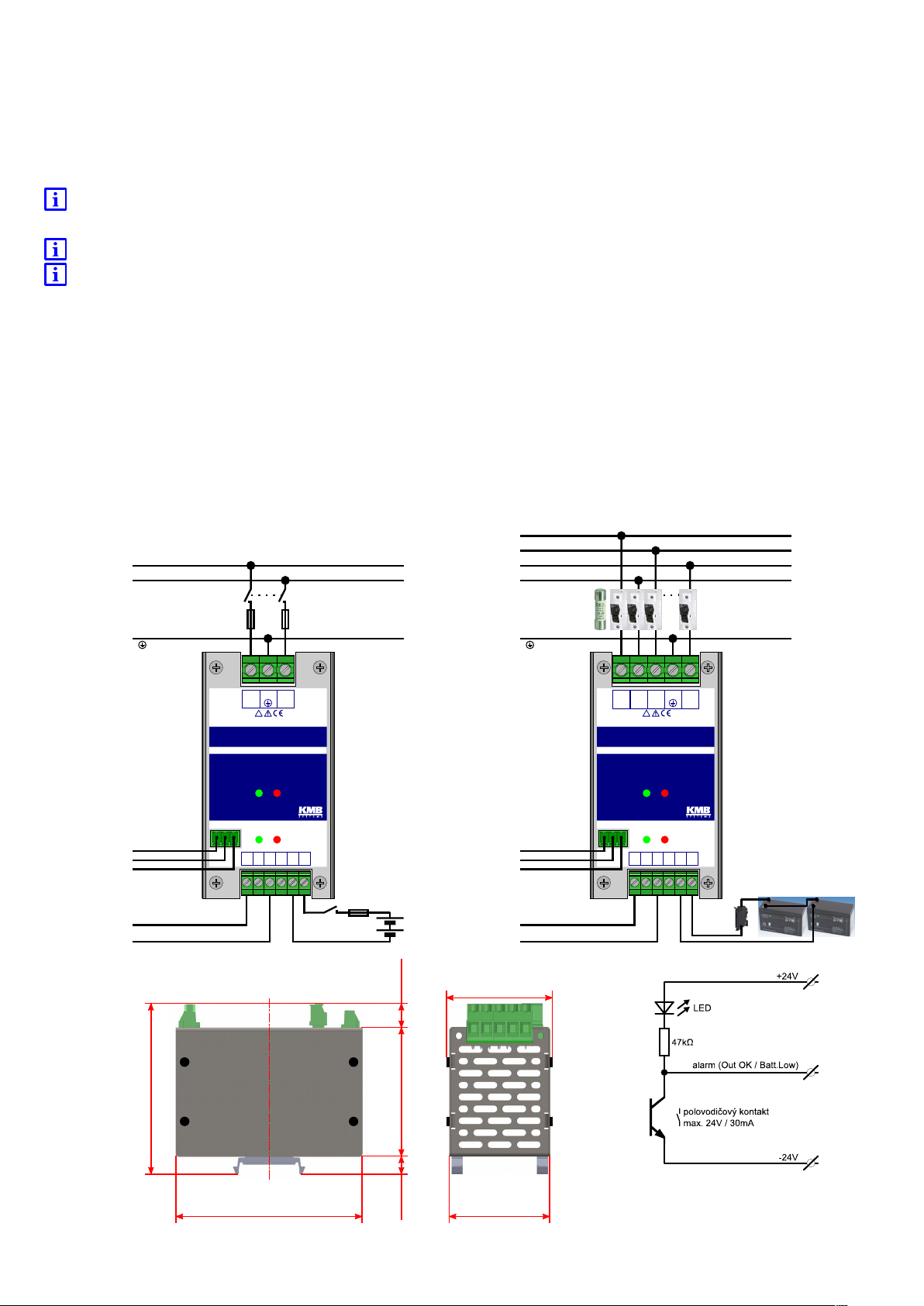
PWR KMB systems
type: PWR 3N 60W 24V type: PWR 3A 60W 24V
Input
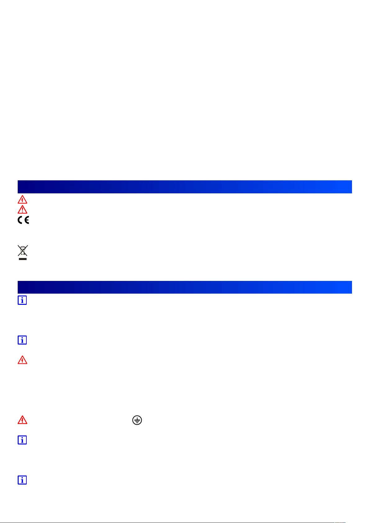
Terminals 0,2÷4mm2 (24÷12AWG), 32A, 0,5÷0,6Nm
Nominal supply voltage 3~, 208/120÷400/230V, 50÷60Hz
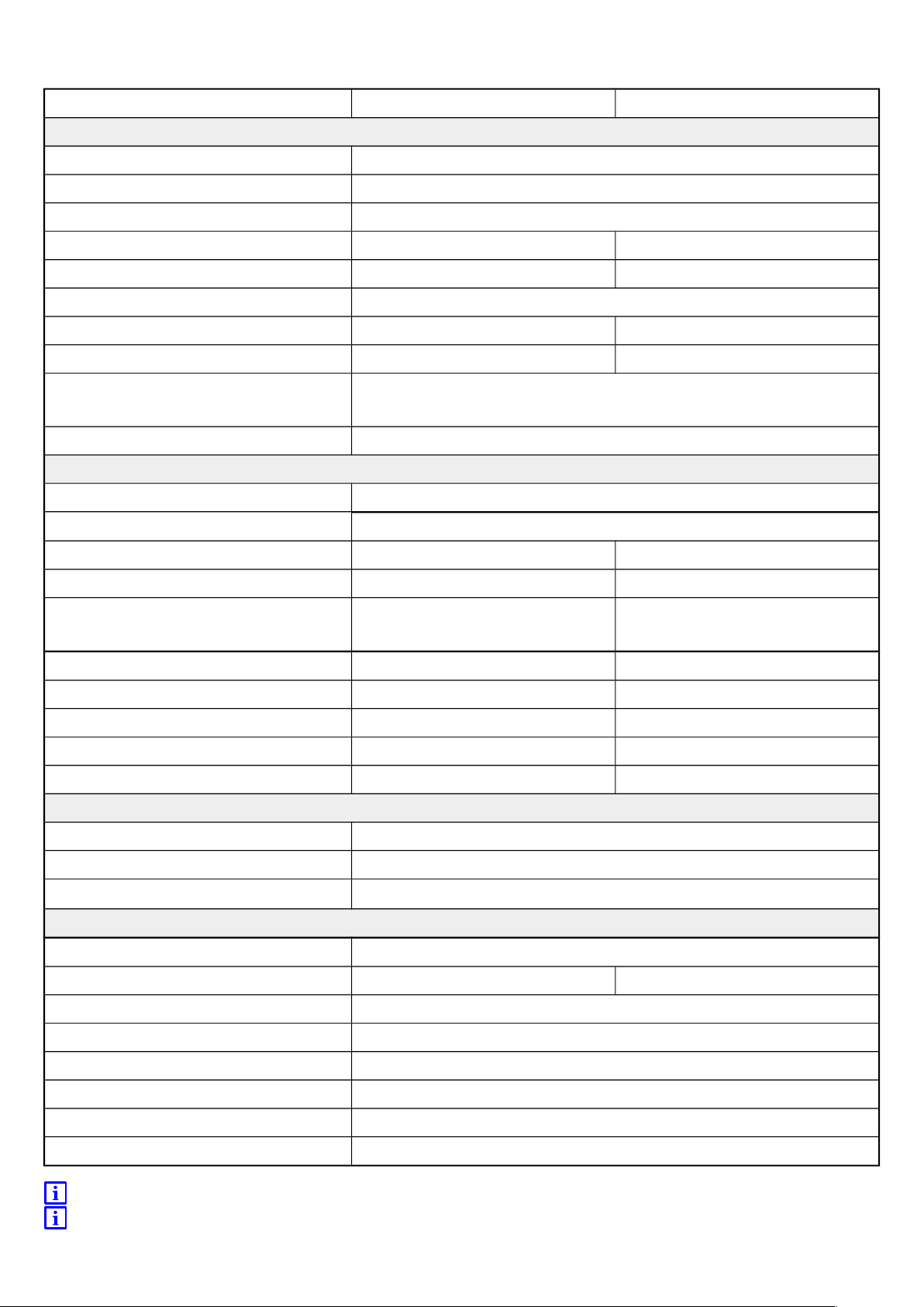
Supply voltage range 1÷3~, 155/90÷460/265V, 47÷63Hz, (see charts)
efficiency (typical) 85% @ 3~400V, 60W 83% @ 3~400V, 60W
power, PF (typical) 140VA, 0,51 @ 3~400V, 60W 125VA, 0,58 @ 3~400V, 60W
Consumption with no load (typical) <30mA @ 3~400V, 7VA, 2W (without accu)
Inrush current (typical) 60A @ 3~400V 60A @ 3~400V
Mains failure immunity (typical) 80ms @ 3~400V Based on accu and load
over-voltage category, safety 300V CAT IV do 2000m.n.m. / 300V CAT III do 5000m.n.m.
ČSN EN 61010-1, ČSN EN 60950-1, protection class I, c,
isolating voltage & resistance (in / out) 3kV~/1min, reinforced insulation, >100MΩ/500V=
output and accumulator
terminals 0,2÷2,5mm2 (24÷14AWG), 24A, 0,5÷0,6Nm
insulation, safety SELV, galvanically insulated from supply voltage
Nominal output voltage 24V 24V
Nominal output power 60W 60W
Nominal output current / range 1,45A / 0÷3A 0,4A / 0÷1,1A
charging current 0,75A
accuracy of output voltage / range ±1% 21÷27,6V
ripple and noise(max.) 240mVP-P ---
over-voltage protection 27,6V 29V
accu. protection (disconnection) --- 21±1V
overload protection (max.) 300% 300%
alarm, s gnal output
Terminals 0,2÷1,5mm2 (24÷16AWG), 12A, 0,2÷0,25Nm
Insulation, safety SELV, galvanically insulated from supply voltage
SSR output
S
30mA/24V=, against ⊝ pole
general
protection, pollution degree IP20, 2, (for 3 contact manufacturer)
operating temperature -30÷70°C (see chart) -20÷70°C (see chart)
storage temperature -40°C÷85°C
Operating and storage humidity 0÷95% RH, non-condensing
EMC – emission ČSN EN 55011, ČSN EN 61000-3-2/-3 – class B
EMC – immunity (61000-4-2/3/4/5/6/8/11) ČSN EN 61326-1, ČSN EN 61000-6-2, ČSN EN 61000-6-5
dimension W 58,6mm x H 109,4mm x D 104,9mm, see drawing
weight, nett 0,25kg (without accu.)
For more information contact producer
Other powers and output voltages have to be consulted with producer.
7