Product Description
The FPT500.247-064-102 is a stand-alone power supply for single phase mains systems, which
provides a stabilized and galvanically separated PELV/ES1 output voltage at 3 outputs.
The negative potential of the outputs is permanently connected toPE within theunit.
The housing is rated as IP65 and IP67 according IEC60529 and provides protection against electrical,
mechanical and fire hazards.
One output fulfills the requirements for a limited power source according toNEC Class2.
The device is equipped with an IO-Link Interface V1.1 to parameterize and access data.
Intended Use
This indoor use device is intended for commercial use, such as in industrial control, process control,
monitoring, measurement or the like. Do not use this device inequipment, where malfunctioning may
cause severe personal injury or threaten human life, without additional appropriate safety devices, that
are suited forthe end-application.
If used in a manner outside of its specification, the protection provided by the device may be impaired.
Installation Instructions
Installthe devicewith the terminals on the bottom of the device. Other mounting orientations require a
reduction in output current. When installing watch out for the risk of injury from sharp edges and
assure that when installed any sharp edges on the back cannot be accessed and cannot cause injury.
Use4 screws ( 2 on top and 2 on bottom mounting holes) suitable for the underground and a strength
comparable to M4 or UNC 8-32 screws.
The device is designed for pollution degree 3 areas in controlled environments.
The enclosure of the device provides a degree of ingress protection of IP65 and IP67 when installed
withall mating connectors firmly connected. Assure that during installation no moisture or dirt gets into
the connections. Operation in areas where moisture or condensation can be expected is possible.
The device is designed as "Class of Protection I" equipment according to IEC 61140. Do not use
without a proper PE (ProtectiveEarth) connection.
For TN,TT mains systems with earthed neutral and IT star mains systems with insulation monitoring
the deviceis designed for overvoltage category III zones up to 2000m (6560ft) and for overvoltage
category II zones up to 5000m (16400ft). For TN, TT, IT delta mains systems or IT star mains systems
without insulation monitoring the device is intended for overvoltage category II zones up to 2000m
(6560ft). The device is designed to be safe in case of a single phase loss and does not require an
external protection.
The device is designed for convection cooling without a fan. Do not obstruct airflow.
The device is designed for altitudes up to5000m (16400ft). Above 2000m (6560ft) a reduction in
output current is required and the operation is limited according the mains systems description above.
Keep the following minimum installation clearances: 50mm on top and bottom, 10mm on the front, the
left and the right side.
The device is designed, tested and approved for branch circuits up to20A (UL) and 32A (IEC) without
additional protection device. If an external fuse is utilized, do not use circuit breakers smaller than 6A
B- or C-characteristic to avoid a nuisance tripping of the circuit breaker.
Makesure that you only use plugs and cables rated for the device output current and the required
temperature range. Follow all local and national codes for installation.
WARNING: Risk of fire or electric shock. Donot connect outputs or devices in parallel for higher
output currents. Do not connect the negative potential of any output to PE.
The maximum permissible ambient air temperature is +70°C (+158°F). The operational temperature is
the sameas the ambient or ambient air temperature and is defined 2cm below the device.
Cleaning only with a damp cloth.
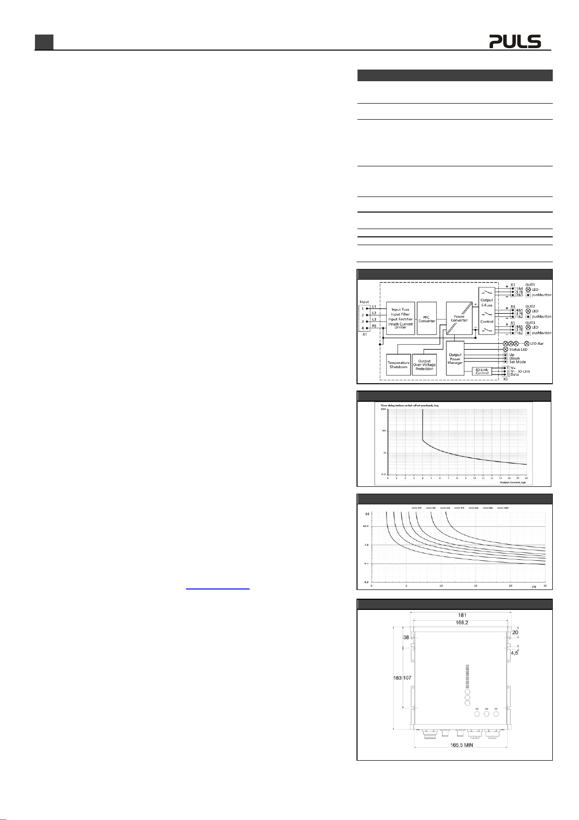
Functional Description
The output is electronically protected against no-load, overload and short circuit and can supply any
kind of loads, including inductive and capacitive loads. If capacitors witha capacitance >20mF are
connected to one output, this output might switchoff after turning the unit or the output on or
connecting the load. Do not apply return voltages from the load to the output terminals higher than
35V. Feed-back energy from a load must be below 2.5J.
The green Status LED reports an output above 90% of the adjusted voltage of a running device and
no output tripped due to overcurrent or overtemperature and all three phase voltages are present.
The device has an internal overtemperature protection. If the temperature is too high theunit shuts
down and starts automatically again after cooling off. Each output will get the same state as before
the shutdown.
In case of an internal defect, a redundant circuit limits the maximum output voltage to32.5V. The
output shuts down and automatically attempts to restart.
IO-Link gives access to internally measured parameters and can be used tochange settings. For
IODD files and additional descriptions please visit www.pulspower.com.
LED bargraph and push-buttons:
The LED bar normally displays the actual output power as percentage value. 100% equals an output
power of 500W. LEDs up to and including 100% are green, the LEDs above 100% are orange. With
pressing theup / down buttons youcan see thepercentage of each output. The orange LED indicates
the selected output.
If you press the "Set Mode" button for 3 seconds all LEDs light up briefly and one LED stays on,
showing theactual output voltage. Withpressing the up or down button you canchange the set
voltage tothe values indicated by the green LED. All orange LEDs are dark. The voltage is set
immediately and the value stored until the next change. If you press the "Set Mode" button again you
can set the output current limit for the selected channel indicated by the orange LED. With the up /
down buttons the current limit is changed to the values indicated by the single lit green LED. The value
is stored until the next change. Select other outputs with the “Set Mode” button. Without further
pressing of push-buttons, the LED bar will return from any other mode to normal mode after15s. With
the buttons at each channel the channel can turned on/off manually by pressing for at least 1s. The
current limit for the NEC Class2 output cannot be changed.
Mating connectors:
Use a 4 Pin 7/8” double coded female plug to connect to the input voltage connector (X1). Pin
assignment: Pin 1 for L1, Pin 2 for L2, Pin 3 for L3; Pin 4 for PE.
Usea standard M12 A-coded 5 pin female plug forthe IO Link.
Usea standard M12 A-coded 5 pin male plug toconnect to the output connector (X3). Pin assignment:
Pin 1 and 4 for plus; Pin 2 and 3 for minus; Pin5: FE (functional earth).
Use 5 Pin 7/8” male plugs for the output voltage connectors(X4, X5). Pin assignment: Pin 4 and 5 for
plus; Pin 1 and 2 for minus; Pin 3: FE (functionalearth).