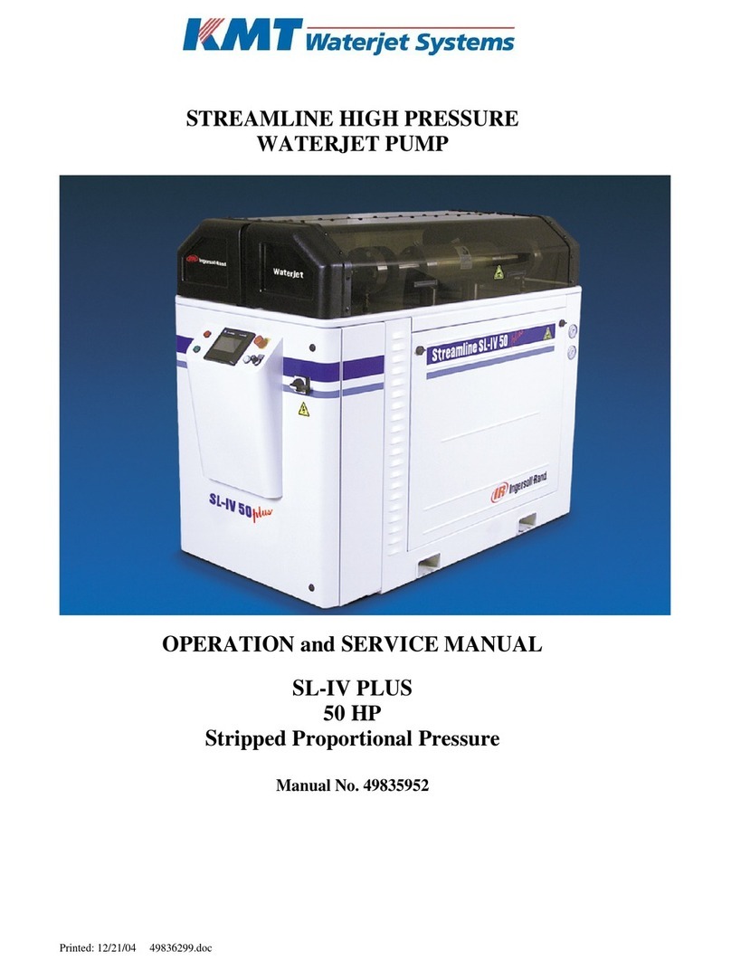
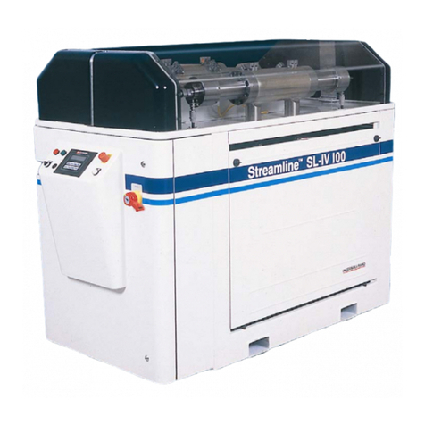
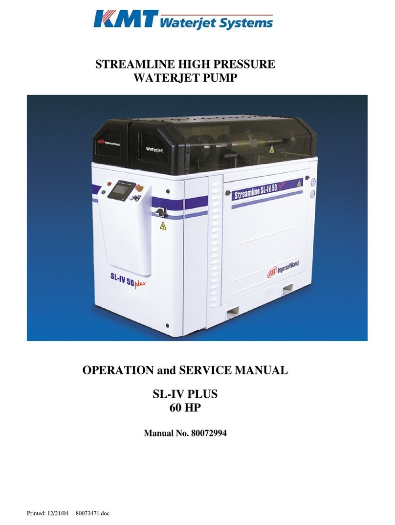
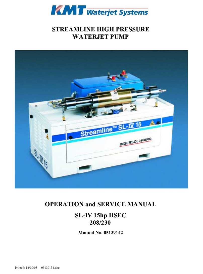
KMT STREAMLINE S30 User manual

MANUAL 20425545(R01)
STREAMLINE S30
WATERJET INTENSIFIER
OPERATION AND MAINTENANCE MANUAL

20425668
5-2005/Rev 0
NOTICE
This document contains subject matter in which KMT Waterjet Systems has proprietary
rights. Recipients of this document shall not duplicate, use or disclose information
contained herein, in whole or in part, for other than the purpose for which this manual
was provided.
KMT Waterjet believes the information described in this manual to be accurate and
reliable. Much care has been taken in its preparation; however, the Company cannot
accept any responsibility, financial or otherwise, for any consequences arising out of the
use of this material. The information contained herein is subject to change, and
revisions may be issued advising of such changes and/or additions.
KMT WATERJET SYSTEMS 2004
KMT Waterjet Systems
635 West 12th Street
POB 231
Baxter Springs, KS 66713-0231
Phone:
Fax: (800) 826-9274
(620) 856-5050

20425668
5-2005/Rev 0 i
TABLE OF CONTENTS
Title Page
Notice
Table of Contents
Appendix
Section Page
1Introduction......................................................................................................1-1
1.1 Overview...............................................................................................1-1
1.2 Performance Features and Options.......................................................1-1
1.3 Operational Overview...........................................................................1-2
Low Pressure Water System.................................................................1-2
Recirculation System............................................................................1-3
Hydraulic System..................................................................................1-3
High Pressure Water System ................................................................1-3
1.4 Safety ....................................................................................................1-4
Lockout/Tagout Procedure....................................................................1-4
Warning Labels.....................................................................................1-5
Emergency Medical Treatment.............................................................1-7
1.5 Worldwide Product Support .................................................................1-7
1.6 Spare Parts ............................................................................................1-8
1.7 Manual Organization ............................................................................1-8
1.8 Equipment and Service Manual Questionnaire.....................................1-8
2Installation........................................................................................................2-1
2.1 Overview...............................................................................................2-1
2.2 Installation Summary............................................................................2-1
2.3 Site Requirements.................................................................................2-2
Transporting..........................................................................................2-3
2.4 Power Requirements.............................................................................2-3
2.5 Service Connections..............................................................................2-4
Cooling Water.......................................................................................2-5
Cutting Water........................................................................................2-6
Optional Drain ......................................................................................2-6
Optional Plant Air.................................................................................2-6
2.6 Flow Requirements...............................................................................2-6
2.7 High Pressure Piping.............................................................................2-7
Measurements and Dimensions ............................................................2-9
Hand Coning.........................................................................................2-10
Power Coning........................................................................................2-11
Hand Threading ....................................................................................2-12
Power Threading...................................................................................2-12
2.8 High Pressure Connections...................................................................2-13

20425668
5-2005/Rev 0 ii
Standard Connections ...........................................................................2-13
Anti-Vibration Connections..................................................................2-14
2.9 Commissioning.....................................................................................2-15
2.10 Decommissioning .................................................................................2-17
3Maintenance .....................................................................................................3-1
3.1 Overview...............................................................................................3-1
3.2 Maintenance..........................................................................................3-1
Daily Inspection....................................................................................3-1
Periodic Maintenance............................................................................3-1
High Pressure System Maintenance......................................................3-2
3.3 Maintenance Precautions......................................................................3-3
4Low Pressure Water System...........................................................................4-1
4.1 Overview...............................................................................................4-1
4.2 Cutting Water Supply Quality ..............................................................4-1
4.3 Operation...............................................................................................4-1
4.4 Optional System Components...............................................................4-1
Operation with Optional Booster Pump and Water Filter ....................4-1
4.5 Service and Maintenance Procedures ...................................................4-3
Filter Assembly Maintenance...............................................................4-3
Booster Pump Adjustment....................................................................4-4
5Recirculation System .......................................................................................5-1
5.1 Overview...............................................................................................5-1
5.2 Operation...............................................................................................5-1
5.3 Service and Maintenance Procedures ...................................................5-2
Hydraulic Oil Maintenance...................................................................5-2
Oil Filter Maintenance..........................................................................5-5
Operating Temperature Adjustment .....................................................5-6
6Hydraulic System.............................................................................................6-1
6.1 Overview...............................................................................................6-1
6.2 Operation...............................................................................................6-1
6.3 Service and Maintenance Procedures ...................................................6-4
Hydraulic Operating Pressure...............................................................6-4
Motor Maintenance...............................................................................6-6
Flexible Coupling Replacement............................................................6-6
Hydraulic Compensator Maintenance...................................................6-10
Hydraulic Pump or Electric Motor Replacement..................................6-13
7Electrical System..............................................................................................7-1
7.1 Overview...............................................................................................7-1
7.2 Optional System Components...............................................................7-1
7.3 Sensors and Solenoids...........................................................................7-1
7.4 Service and Maintenance Procedures ...................................................7-6
Proximity Switch Maintenance.............................................................7-6

20425668
5-2005/Rev 0 iii
8High Pressure Water System..........................................................................8-1
8.1 Overview...............................................................................................8-1
8.2 Optional System Components...............................................................8-1
8.3 Operation...............................................................................................8-1
High Pressure Dump Valve ..................................................................8-3
Redundant Models................................................................................8-3
8.4 System Components..............................................................................8-4
8.5 Service and Maintenance Overview .....................................................8-6
Torque Specifications ...........................................................................8-7
Specialized Maintenance Tools ............................................................8-9
8.6 High and Low Pressure Water Piping...................................................8-10
8.7 High Pressure Cylinder Assembly........................................................8-10
High Pressure Cylinder Assembly Removal.........................................8-11
High Pressure Cylinder Assembly Installation.....................................8-12
High Pressure Cylinder Maintenance ...................................................8-13
8.8 Hard Seal End Caps..............................................................................8-14
Hard Seal End Cap Removal ................................................................8-14
Hard Seal End Cap Installation.............................................................8-15
8.9 Sealing Head.........................................................................................8-16
High Pressure Discharge Check Valve.................................................8-17
Low Pressure Inlet Check Valve...........................................................8-18
Sealing Head Maintenance ...................................................................8-19
8.10 High Pressure Seal Assembly...............................................................8-20
8.11 Hydraulic Cartridge Seal and Plunger Removal...................................8-22
Plunger Maintenance ............................................................................8-24
Plunger Installation...............................................................................8-25
Hydraulic Cartridge Seal.......................................................................8-25
8.12 Hydraulic Piston....................................................................................8-27
Hydraulic Piston Removal....................................................................8-27
Bearing Rings and Seal Assembly........................................................8-29
Plunger Button Sockets, Seals and Retainer Pins.................................8-30
Internal Check Valves...........................................................................8-30
Hydraulic Piston Installation.................................................................8-31
8.13 Hydraulic Cylinder Maintenance..........................................................8-32
8.14 High Pressure Attenuator......................................................................8-32
8.15 Optional High Pressure Dump Valve ...................................................8-33
Pneumatic Control Valve......................................................................8-34
Pneumatic Actuator...............................................................................8-37
8.16 Weep Holes...........................................................................................8-38
9Troubleshooting ...............................................................................................9-1
9.1 Overview...............................................................................................9-1
9.2 Troubleshooting Guide.........................................................................9-2
10 Specifications....................................................................................................10-1
10.1 Overview...............................................................................................10-1
10.2 Installation Specifications.....................................................................10-1
Environment..........................................................................................10-1
Equipment Dimensions and Weights....................................................10-2

20425668
5-2005/Rev 0 iv
Service Connections..............................................................................10-2
10.3 Water Specifications.............................................................................10-2
Cutting Water Supply ...........................................................................10-2
Recirculation System............................................................................10-3
Water Quality Standards.......................................................................10-3
10.4 Electrical Specifications........................................................................10-6
Electrical System ..................................................................................10-6
Ampacity and Power Voltage Requirements........................................10-6
10.5 Hydraulic and High Pressure System Specifications............................10-6
Hydraulic System..................................................................................10-6
High Pressure Water System ................................................................10-7
Orifice Capacity....................................................................................10-7
Torque Specifications ...........................................................................10-8
11 Parts List...........................................................................................................11-1
11.1 Overview...............................................................................................11-1
11.2 Part Nomenclature ................................................................................11-2
11.3 Index .....................................................................................................11-3
APPENDIX
Exhibit
Electrical Schematics
Material Safety Data Sheets

20425553
5-2005/Rev 0 1-1
SECTION 1
INTRODUCTION
1.1 Overview
The Streamline S30, specifically designed for integration into a waterjet cutting system, combines
all the unique capabilities and advantages of waterjet cutting with the reliability, ease of operation
and service support that have made KMT Waterjet Systems a leader in waterjet technology.
The S30 does not include a control panel or enclosure and will not run as a stand-alone unit. An
electrical interface allows the system builder to supply all power, control and logic interface to
the intensifier from the motion control panel. The entire cutting system can be operated and
controlled from one location.
Table 1-1
Streamline S 30
Motor
Horsepower
Rating
HP Kw
Maximum
Operating
Pressure
Maximum
Flow Rate
(at full pressure)
Maximum Single
Orifice Diameter
(at full pressure)
30 22 60,000 psi (4,137 bar) 0.52 gpm (2.0 L/min) 0.010 inch (0.254 mm)
The S30 is available with a single or redundant intensifier. The redundant unit allows operation
to continue if a problem is detected on the active intensifier. Operation can be switched to the
secondary intensifier until the next convenient shutdown, when service can be performed on the
primary intensifier.
1.2 Performance Features and Options
The S30 is designed with the same convenience and ease of access for maintenance and service
you have come to expect from KMT Waterjet. The hydraulic cylinder head simply bolts to the
hydraulic cylinder; each high pressure assembly can be removed and serviced independently, and
the hydraulic seal cartridge can be quickly replaced as a single unit.
The robust performance and standard features are the result of aggressive development and
decades of experience.
•Continuous operation at 60,000 psi (4,137 bar).
•The innovative hard seal end cap provides a metal-to-metal seal against the sealing head,
totally, eliminating the potential for leaks.
•While dramatically increasing seal life, the unique design of the patented HyperLifeTM
seal conforms to the cylinder bore as it expands under pressure, creating an absolute seal.

Section 1
Introduction
20425553
5-2005/Rev 0 1-2
•Each long, slow stroke of the plunger moves more water, while reducing seal and
component wear.
The following options are available at the time of purchase, or as upgrades for existing
equipment.
•A booster pump and low pressure water filter ensure water quality and supply to the high
pressure system.
•A safety dump valve instantly releases high pressure from the system.
•The individual cables in the electrical wiring harness are attached to terminal blocks inside
the optional junction box.
•Proportional pressure control provides remote control of hydraulic operating pressure.
1.3 Operational Overview
The following provides a brief overview of the function and primary components associated with
the individual systems. A detailed discussion of each system is provided in Sections 4 through 8.
Equipment specifications are provided in Section 10, Specifications.
Low Pressure Water System
The low pressure water system supplies the cutting water flow to the intensifier. The optional
booster pump and low pressure water filter assembly enhance performance and allow the pressure
of the cutting water supply to be monitored.
Figure 1-1: System Components

Section 1
Introduction
20425553
5-2005/Rev 0 1-3
Recirculation System
The recirculation system is a cooling and filtration system that provides properly conditioned oil
to the main hydraulic system. Major system components include the recirculation pump, heat
exchanger, oil filter assembly and the hydraulic oil reservoir.
Hydraulic System
The hydraulic system supplies the intensifier with the hydraulic oil required to produce high
pressure water. Major system components include the electric motor, hydraulic pump, and the 4-
way directional control valve mounted on the hydraulic manifold.
High Pressure Water System
The high pressure water system is the heart of the waterjet system. Water is pressurized and
continuously delivered to the cutting head. As water passes through a tiny hole in the orifice,
water pressure is converted to water velocity capable of cutting most any material.
The major components include the high pressure cylinder assemblies, hydraulic cylinder
assembly, hydraulic piston, attenuator and the optional safety dump valve.
Figure 1-2: High Pressure System Components

Section 1
Introduction
20425553
5-2005/Rev 0 1-4
1.4 Safety
The high pressure waterjet cutting system is a high energy cutting tool capable of cutting many
dense or strong materials. Do not touch or be exposed to high pressure water. High pressure
water will penetrate all parts of the human body. The liquid stream and the material ejected by
the extreme pressure can result in severe injury.
All personnel operating, servicing or working near the waterjet cutting equipment shall adhere to
the following safety precautions, as well as the applicable plant safety precautions.
•Only KMT factory trained, qualified personnel shall service and maintain the
equipment.
•The operator shall practice and promote safety at all times to avoid potential
injury and unnecessary downtime.
•The operator shall ensure that the work area around the equipment is clean and
free of debris and oil spills.
•All protective guards, shields or covers shall be in place on the equipment at all
times.
•
Safety glasses and ear protection shall be worn when operating or
working near the equipment.
Lockout/Tagout Procedure
This lockout/tagout procedure is designed to protect all employees from injuries caused by the
unexpected energizing or startup of the machine, or the release of stored energy during service
and maintenance.
This is accomplished with energy isolating devices that prevent the transmission or release of
energy. An energy source is any source of electrical, mechanical, hydraulic, pneumatic,
chemical, thermal, or other energy source that could cause injury to personnel.
A lockout device utilizes a lock and key to hold an energy isolating device in the safe position
and prevents the machine from being energized. A tagout device is a prominent warning device
that can be securely attached to the machine warning personnel not to operate the energy isolating
device. This procedure requires the combination of a lockout device and a tagout device.
The lockout/tagout procedure applies to any employee who operates and/or performs service or
maintenance on the machine. Before any maintenance or repairs are performed, the machine
shall be isolated, and rendered inoperative as follows.
1. Shut down the machine and open the high pressure cutting water valve to bleed the water
and hydraulic pressure from the system.
2. Disconnect, lockout and tag the main, customer supplied, power source.

Section 1
Introduction
20425553
5-2005/Rev 0 1-5
3. Close, lockout and tag the manual shutoff valves for all service connections: cutting water
in, cooling water in and out, and air.
Warning Labels
Warning labels are posted on the machine to indicate potential hazards. The operator and service
personnel shall pay particular attention to these warning labels. Table 1-2 describes the necessary
precautions and provides the part number required to order replacement labels.
Table 1-2
Warning Label Precautions
1
P/N 05114962
The electric motor and optional junction box can
present an electrical shock hazard. Always disconnect
and lockout the main power before performing any type
of maintenance.
2
P/N 05114970
The surface of high pressure water and hydraulic
components becomes hot during normal operation.
Failed, or failing components, can become extremely
hot during operation.
3
P/N 05098017
High pressure water and/or hydraulic pressure can
remain in the system even when the pump has been shut
off. All pressure can be safely bled from the system by
opening the high pressure cutting water valve for a few
seconds after shutting off the pump.

Section 1
Introduction
20425553
5-2005/Rev 0 1-6
Table 1-2
Warning Label Precautions
4
P/N 20415794
All personnel involved in the installation, operation
and/or service of the intensifier must carefully read,
understand and follow the procedures in this manual to
avoid creating unsafe conditions, risking damage to the
equipment, or personal injury.
Safety precautions and warnings for specific procedures are emphasized throughout this manual
as illustrated in the following examples. These precautions must be reviewed and understood by
operating and maintenance personnel prior to installing, operating or servicing the machine.
Adherence to all Warnings, Cautions and Notes is essential to safe and efficient service and
operation.
Warnings emphasize operating or service procedures, or conditions that can result
in serious personal injury or death.
Cautions emphasize operating or service procedures, or conditions that can result in
equipment damage or impairment of system operation.
NOTE
Notes provide additional information that can expedite or improve operating or
service procedures.

Section 1
Introduction
20425553
5-2005/Rev 0 1-7
Emergency Medical Treatment
An emergency medical card is included in the binder of this manual. This information should be
used to aid in the treatment of a waterjet injury. Additional cards may be obtained by contacting
KMT Waterjet Systems using the address or telephone number shown on the card.
Medical Alert
This card is to be carried by personnel working
with high pressure waterjet equipment. Obtain
medical treatment immediately for ANY high
pressure waterjet injuries.
KMT Waterjet Systems
635 West 12th Street
Baxter Springs, KS 66713
(620) 856-2151
This person has been working with water jetting at
pressures to 60,000 psi (414 MPa, 4137 bar, 4,218
Kg/cm2) with a jet velocity of 3,000 fps (914 mps).
Foreign material (sand) may have been injected with
water. Unusual infections with microaerophilic
organisms occurring at lower temperatures have been
reported, such as gram negative pathogens as are
found in sewage. Bacterial swabs and blood cultures
may therefore be helpful. This injury must be treated
as an acute surgical emergency and be evaluated by a
qualified surgeon. Circulation may be compromised,
therefore, DO NOT APPLY HEAT TO INJURED
PART. For first aid: (1) Elevate injured part (2)
Antibiotics (3) Keep injured person NPO.
1.5 Worldwide Product Support
The KMT Waterjet Customer Service Department is available to answer your questions regarding
equipment installation and service. Technical assistance is available by phone and on-site support
is available on request.
On-site technical assistance is available during equipment installation and startup. Additionally,
technical support for service and maintenance issues and training of operators and maintenance
personnel is available. Periodic training sessions are also conducted at KMT Waterjet and
customer facilities.
Contact the KMT Waterjet Customer Service Department for additional information.
USA Customer Service Manager Europe Technical Manager
KMT Waterjet Systems
635 West 12th Street
Baxter Springs, KS 66713
USA
Phone: (620) 856-2151
Fax: (620) 856-5050
Email:
KMT Waterjet Systems GmbH
Wasserstrahl-Schneidetechnik
Auf der Laukert 11
D-61231 Bad Nauheim
Germany
Phone: +49-6032-997-117
Fax: +49-6032-997-270

Section 1
Introduction
20425553
5-2005/Rev 0 1-8
1.6 Spare Parts
KMT Waterjet maintains a well-stocked Spare Parts Department, staffed by trained,
knowledgeable personnel. If required, emergency shipment is available. Contact the Customer
Service Department to order spare parts, or for additional information.
1.7 Manual Organization
This manual contains operating and maintenance procedures for the Streamline S30. Information
is organized as follows:
NOTE
The procedures, guidelines and parts list included in this document pertain only to
the factory installed components from KMT Waterjet Systems. Modifications or
additions made by the system builder are not addressed.
•Section 1, Introduction, provides an overview of equipment features and options, a brief
operational overview, details regarding safety issues and contact information for product
support.
•Section 2, Installation, details installation requirements and procedures. Guidelines for
commissioning the intensifier are also provided.
•Section 3, Maintenance, highlights routine and preventive maintenance requirements.
Precautions associated with high pressure cutting equipment are also reviewed.
•Sections 4 through 8 are specific to each individual system. Each section contains a
detailed description of the principles of operation and the function of each system.
Routine maintenance procedures associated with the system are also detailed.
•Section 9, Troubleshooting, is a comprehensive guide containing the information required
to diagnose problems and repair the machine.
•Section 10, Specifications, contains a comprehensive list of equipment specifications; a
detailed discussion of water quality standards and treatment guidelines; as well as
horsepower requirements for various orifice sizes.
•Section 11, Parts List, contains part numbers, descriptions and drawings to facilitate the
ordering of replacement parts.
1.8 Equipment and Service Manual Questionnaire
We are interested in your impression of the KMT Waterjet System recently installed at your
location. Your comments and recommendations will aid us in our continuing goal to improve our
products, and make our technical information more useful to our customers.
At your convenience, please take a few minutes to complete the following questionnaire, and
return it to the applicable Customer Service Department listed above.

20425553
5-2005/Rev 0 1
Equipment and Service Manual Questionnaire
1. General Appearance
Was the unit received in good condition? Yes No
Comments:
Is the unit a convenient size? Yes No
2. Controls
Are the controls user friendly? Yes No
Is the unit easy to operate? Yes No
Comments:
3. Performance
Does the unit perform smoothly and meet your expectations? Yes No
Does the unit run quietly? Yes No
Comments:
4. Did the installation and startup go smoothly? Yes No
Comments:
5. What features do you consider the most significant?
Quiet operation
Appearance
Performance/Operation
Repair/Maintenance
Other
6. What areas could be improved?
Appearance
Performance
Serviceability
Other

Equipment and Service Manual Questionnaire
20425553
5-2005/Rev 0 2
7. Manual Organization
Does the Table of Contents help you find topics easily? Yes No
Comments:
Is the information well organized? Yes No
Comments:
Is the page layout suitable for the material being presented? Yes No
Comments:
8. Graphics
Are the illustrations suitable for the material being presented? Yes No
Comments:
9. Text
Does the information adequately explain how to operate and service the
equipment? Yes No
Comments:
Are there paragraphs or procedures you feel need clarification? Please identify
them by page number and add your comments. Yes No
Comments:
Is there anything you would add or delete to make the manual more useful? Yes No
Comments:
Is there any information that should receive more emphasis? Yes No
Comments:
Name Title
Company Date
Address

20425561
5-2005/Rev 0 2-1
SECTION 2
INSTALLATION
2.1 Overview
Installation and commissioning requirements and procedures are detailed in this section. These
procedures require a thorough understanding of the individual components and systems, safety
issues, and the overall operation of the intensifier.
All personnel involved in the installation, operation and/or service of the intensifier must
carefully review this manual prior to installing and commissioning the machine.
The Technical Service Department at KMT Waterjet Systems is available to assist in the
installation and commissioning process. Service and repair training for maintenance personnel is
also available.
2.2 Installation Summary
The following summary lists the procedures required for the installation and commissioning of
the intensifier system. Details and requirements for each item are discussed in this section.
•Properly sized power drops with fused disconnects or circuit breakers, and properly sized
starting components must be installed.
•Plumbing and manual shutoff valves for the inlet and outlet cooling water, and the inlet
and outlet cutting water must be installed.
Incoming source water must meet specific water quality standards, flow rates and pressure
requirements. It may be necessary to install water conditioning and/or pressure boosting
equipment to meet these water purity and pressure requirements.
•High pressure tubing runs from the intensifier to the cutting station must be installed with
the appropriate mountings, support brackets and hardware.
•Wiring must be installed and connected between the intensifier and the cutting station
control system.
•If the unit is equipped with an optional booster pump or dump valve, drain water
plumbing must be suitably located and installed for the proper disposal of wastewater.
•If the unit is equipped with an optional dump valve, a pneumatic drop with a manual
shutoff valve and regulator for the air connection must be installed.
•The machine must be commissioned and tested.

Section 2
Installation
20425561
5-2005/Rev 0 2-2
2.3 Site Requirements
The intensifier must be installed indoors where air borne dust and contaminants are minimal. The
ambient temperature should be between 40°F (5°C) and 104°F (40°C), with a maximum
relative humidity of 95 percent.
Refer to Table 2-1, Equipment Dimensions and Weight, to establish a suitable installation site. A
minimum clearance of 36 inches (914 mm) should be provided on all sides of the machine to
facilitate service.
Figure 2-1: Equipment Dimensions
Table 2-1
Equipment Dimensions and Weight
Total Length Base Length Width Height Weight
53.50” (1,359 mm) 44.00” (1,117 mm) 32.39” (823 mm) 37.00” (940 mm) 1,750 lbs (794 kg)
Redundant Model
39.07” (992 mm) 28.25” (718 mm) 2,030 lbs (921 kg)

Section 2
Installation
20425561
5-2005/Rev 0 2-3
Transporting
The weight of the machine is not evenly distributed from one end to the other. Note the warnings
stamped on the crate. The center of gravity is clearly identified on the sides of the crate. The
forklift should be positioned accordingly.
When the machine has been removed from the crate, note the position of the fork pockets on the
bottom of the machine. The pockets are positioned in relationship to the center of gravity to
balance the weight on the forklift.
Figure 2-2: Fork Pockets
The machine must be lifted from the bottom. Do not attempt to lift the machine
from the intensifier.
2.4 Power Requirements
Power supplied to the pump and wiring for remote control must comply with local, regional and
national electrical codes. Service voltage and ampacity must meet the requirements detailed in
Table 2-2. Voltage fluctuations in excess of +/- 10 percent of nominal voltage may damage the
machine and void the warranty.

Section 2
Installation
20425561
5-2005/Rev 0 2-4
Table 2-2
Ampacity and Power Voltage Requirements
Power Voltage Motor
Horsepower Full Load
Amps Recommended
Circuit Breaker Amps
208/3/50-60 30 86 125
230/3/60 30 76 100
400/3/50 30 43 60
415/3/50 30 43 60
460/3/60 30 38 50
575/3/60 30 32 40
2.5 Service Connections
The intensifier requires two incoming water sources, cooling water and cutting water; a drain line
for cooling water and a high pressure discharge line. A drain line for wastewater is required for
units equipped with an optional dump valve or booster pump. The optional dump valve also
requires an air supply line. All piping must comply with local, regional and national codes.
With the exception of the wastewater drain line, manual shutoff valves should be installed for all
connections. To facilitate service, the valves should be located as close as practical to the
interface connection.
Thoroughly purge all supply plumbing prior to connection to remove any residue
that could contaminate the system.
Table of contents
Other KMT Water Pump manuals
Popular Water Pump manuals by other brands

Kohler
Kohler TP 3.0 Service manual

Wilden
Wilden Advanced Series Engineering, operation & maintenance

Endress
Endress EMP 205 Translation of the original operating manual

PEERLESS
PEERLESS PVF Series Installation and operating instructions

Graco
Graco Therm-O-Flow Plus HM55-D Series instructions

Sandpiper
Sandpiper S07B1P2PPNS000 Operating and service manual