Knauer AZURA HPLC User manual

HPLC
Air sensor
Supplement
Document no. V6879

For your own safety, read the manual and always observe the
warnings and safety information on the device and in the
manual.
Technical Support:
Phone: +49 30 809727-111 (9-17h, Central European Time)
Fax: +49 30 8015010
E-Mail: [email protected]
Languages: German, English
Publisher:
KNAUER Wissenschaftliche Geräte GmbH
Hegauer Weg 38
D-14163 Berlin
Phone: +49 30 809727-0
Fax: +49 30 8015010
Internet: www.knauer.net
E-Mail: [email protected]
Version information:
Article number: V6879
Version number: 1.3
The information in this document is subject to change without prior
notice.
For latest version of the manual, check our website:
http://www.knauer.net/en/Support/User-Manuals
Copyright:
© KNAUER Wissenschaftliche Geräte GmbH 2018. All rights reserved.
AZURA® is a registered trademark of KNAUER Wissenschaftliche
Geräte GmbH.
Printed in Germany on environmentally
friendly paper from sustainable forests.

Table of Contents 3
Airsensor Supplement, V6879
Table of Contents
NOTE For your own safety, read the manual and always
observe the warnings and safety information on the
device and in the supplement.
NOTE Technical data are subject to change without notice.
Please check our website for latest updates and
changes.
Intended Use . . . . . . . . . . . . . . . . . . . . . . . . . . . . . . . . . . . . . . . . . . . 4
Installation . . . . . . . . . . . . . . . . . . . . . . . . . . . . . . . . . . . . . . . . . . . . . 5
Calibration . . . . . . . . . . . . . . . . . . . . . . . . . . . . . . . . . . . . . . . . . . . . . 6
Integrating into PurityChrom®. . . . . . . . . . . . . . . . . . . . . . . . . . . . . 6
Holding the Run . . . . . . . . . . . . . . . . . . . . . . . . . . . . . . . . . . . . . . 8
Continuing the Run. . . . . . . . . . . . . . . . . . . . . . . . . . . . . . . . . . . . 9
Repeat Orders . . . . . . . . . . . . . . . . . . . . . . . . . . . . . . . . . . . . . . . . . 10

4IntendedUse
Airsensor Supplement, V6879
Intended Use
The airsensor displays the end of buffer or the end of sample by detect-
ing air. It protects the column from damage caused by intruding air and
supports the automatic sample injection. The airsensor can be used with
different transparent 1/16”, 1/8” or 1/4” tubings.
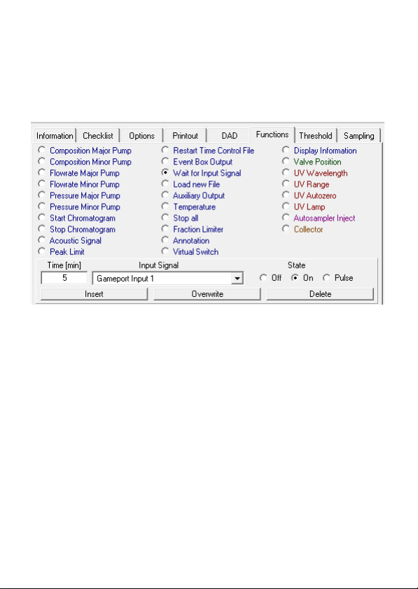
The delivery consists of the airsensor, an amplifier, and a gameport
adapter. The gameport adapter can be connected to a computer.
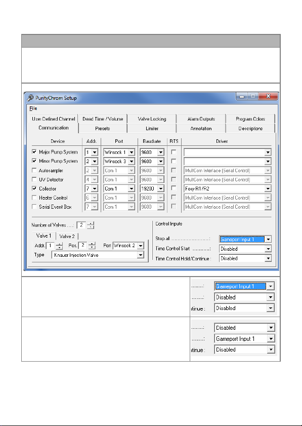
The airsensor is controlled by KNAUER software PurityChrom® which
supports up to 4 airsensors. Upon detecting air, you can program differ-
ent actions. The purification can either be stopped or paused to prevent
air from entering the system. Furthermore, after detecting the end of
the sample, you program the software to automatically start or continue
the run.
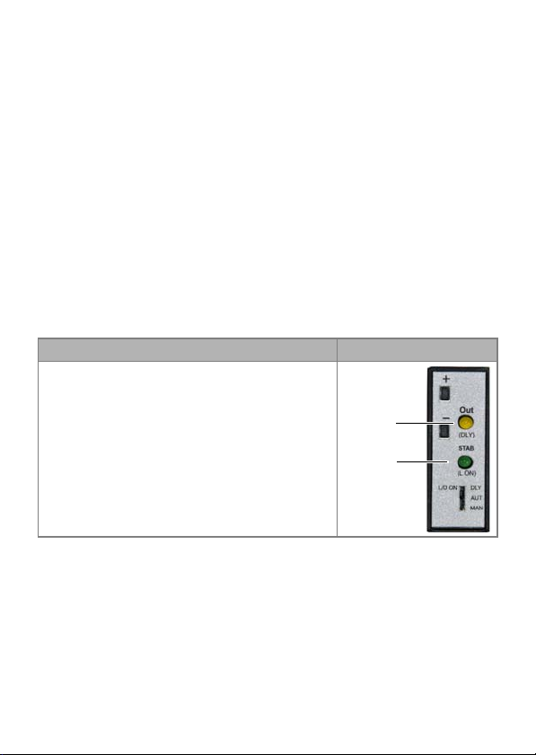
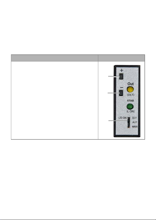
The LEDs of the amplifier indicate the status of the airsensor:
LED color Figure
Yellow LED Out 1:
Lights up in case air has been detected
Green LED STAB 2:
Lights up permanently to show that the
signal is stable
In case of flickering, calibration is recom-
mended
1
2

Installation 5
Airsensor Supplement, V6879
Installation
See below for a description on how to mount the airsensor onto the tub-
ing and on how to connect it to a computer. You can attach the airsen-
sor to the side panel of your AZURA L device with AZURA Click. Select a
position for the air detection on the tubing, then start the installation.
NOTE The number of the airsensor corresponds to the num-
ber on the cable that is being used. If you have more
than one airsensor, connect the other amplifiers to the
free cables.
Process Figures
1. Connect the Sub-D15 plug 1with the
gameport adapter 2.
2. Connect the gameport adapter per USB
to your computer.
3. Connect the amplifier 3to one of the 4
numbered cables.
4. Clamp the airsensor 3onto the tubing
at the selected position.
1
2
3
4

6Calibration
Airsensor Supplement, V6879
Calibration
You must calibrate the airsensor before use or in case the signal is unsta-
ble. For that purpose, make sure that you can operate the amplifier.
NOTE During calibration, the green LED STAB blinks rapidly. If
calibrating has been successful, the same LED blinks
slowly for approximately 3 s.
Integrating into PurityChrom®
You can program the software to either start or stop the system after an
air bubble has been detected.
NOTE You have to choose the Gameport Input 1, 2, 3, or 4
which equals the airsensor number.
Process Figure
1. Move the switch 3to DLY.
2. Press the button - 2.
The STAB signal disappears. Both lights
should be turned off.
3. Move the switch to AUT.
4. Press the button + 1where the tubing is
filled with air.
5. Press the button - where the tubing is
filled with liquid.
1
2
3

Integrating into PurityChrom® 7
Airsensor Supplement, V6879
Process and figures
1. Open the PurityChrom® Setup.
2. Go to the register Communication.
3. In the section Control Inputs you can make the necessary changes.
4. To stop the system, change the settings
as follows in Fig.
5. To start a run, change the settings as fol-
lows:

8 Integrating into PurityChrom®
Airsensor Supplement, V6879
Holding the Run
To hold the run at air detection, you can program a threshold over your
complete run in the register Thresholds of the Time Control Editor.
NOTE You have to choose the Gameport Input 1, 2, 3, or 4
which equals the airsensor number.
Process Figures
1. To open the Time Control Editor, press
the button .
2. Go to the register Threshold.
3. Choose the Gameport Input 1 from the
dropdown list.
4. Click on the start value of the threshold
parameter in the picture (indicated by
the arrow). The appearance of the regis-
ter changes.
5. Change the setting for Operation to Hold
current run.
6. Click on the button Insert to confirm the
changes.

Integrating into PurityChrom® 9
Airsensor Supplement, V6879
Continuing the Run
To continue the run after air has been detected, you can activate the set-
ting in the register Functions of the Time Control Editor. Start writing
your method as usual and activate the function Wait for Input Signal at a
particular time during the method.
NOTE Make sure that the functions succeeding the function
Wait for Input Signal start with a delay of 0.01 s.
NOTE Do not activate the option Stop Pumps at Time Control
Hold in the register Options. Otherwise the pump stops
after the function Wait for Input Signal has been
reached.
NOTE You have to choose the Gameport Input 1, 2, 3, or 4
which equals the airsensor number.

10 Repeat Orders
Airsensor Supplement, V6879
Repeat Orders
Process Figures
1. To open the Time Control Editor, press
the button .
2. Go to the register Functions.
3. Activate the function Wait for Input Sig-
nal.
4. Choose the Gameport Input 1 from the
dropdown list.
5. Activate On in the section State.
6. Click on the button insert to confirm the
changes.
7. After reaching the function Wait for Input
Signal, the run pauses until the end of
sample. After the signal, the run contin-
ues automatically.
Name Order number
Airsensor for 1/16” tubing A70092
Additional airsensor without wiring for 1/16”
tubing
A70092-1
Airsensor for 1/8” tubing A70093
Additional airsensor without wiring for 1/8”
tubing
A70093-1
Airsensor for 1/4” tubing A70083
Additional airsensor without wiring for 1/4”
tubing
A70083-1
AZURA Click A70096
Distribution box 24 V AZS80SA

Latest KNAUER instructions online:
https://www.knauer.net/en/Support/User-manuals
KNAUER
Wissenschaftliche Geräte GmbH
Hegauer Weg 38
14163 Berlin
Phone: +49 30 809727-0
Fax: +49 30 8015010
E-Mail: [email protected]
Internet: www.knauer.net
© KNAUER 2018
Table of contents