Safety Diaphragm pump N85, N86
6 Translation of original Operating and Installation Instructions, english, KNF 121258-121528 01/20
Hence, make sure the temperature of the medium is sufficiently
below the ignition temperature of the medium, even when it is
compressed to the maximum permissible operating pressure of the
pump. The maximum permissible operating pressure of the pump
is stated in the technical specifications (Chapter 4).
If necessary, consider any external sources of energy, such as
radiation, that may add heat to the medium.
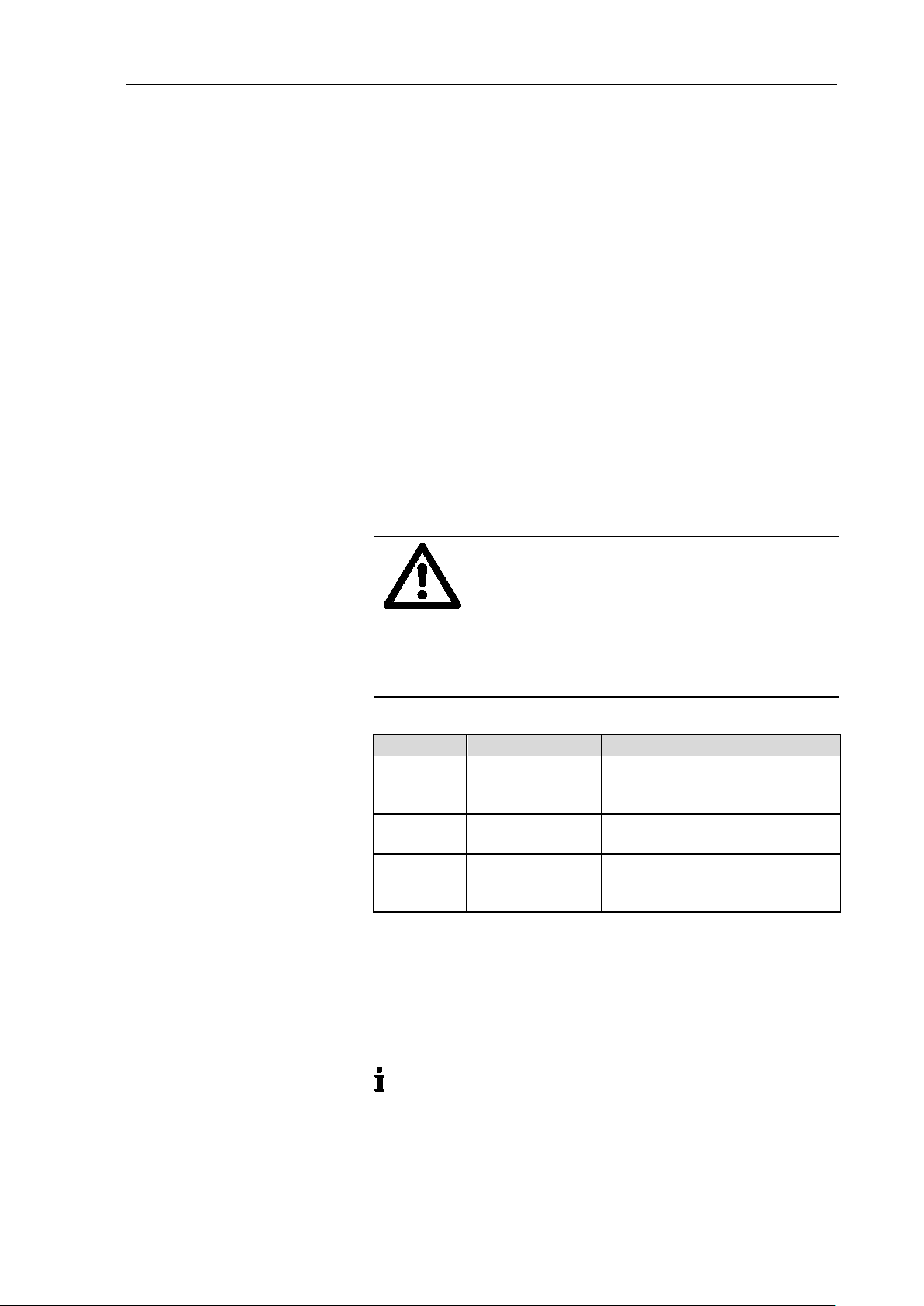
For pumps with AC motor:
When the operation of the pump is interrupted by the thermal
switch, the pump will re-start automatically after cooling down.
Take all care necessary to prevent this leading to a dangerous
situation.
In case of doubt, consult the KNF customer service.
Store all replacement parts in a protected manner and dispose of
them properly in accordance with the applicable environmental
protection regulations. Observe the respective national and inter-
national regulations. This especially applies to parts contaminated
with toxic substances.
For the purposes of the Machinery Directive 2006/42/EC, pumps
are “partly completed machinery”, and are therefore to be regarded
as not ready for use. Partly completed machinery may not be
commissioned until such time as it has been determined that the
machine in which the partly completed machinery is to be assem-
bled is in conformity with the provisions of the Machinery Directive
2006/42/EC. The following essential requirements of Annex I of
Directive 2006/42/EC (general principles) are applied and ob-
served:
−General Principles No. 1
−No. 1.1.2. / 1.1.3. / 1.3.1. / 1.3.3. / 1.3.4. / 1.4.1. / 1.5.1.* /
1.5.2.* / 1.5.8. / 1.5.9. / 1.7.4. / 1.7.4.1. / 1.7.4.3.
(*only for pumps with AC motor)
As these partly completed machinery are OEM-models the power
supplies and the equipment for disconnecting and switching-off the
partly completed machinery respectively have to be considered
when mounting as well as over-current and overload protective
gear.
In addition a protection against mechanical parts in motion and hot
parts, if existing, has to be provided when mounting.
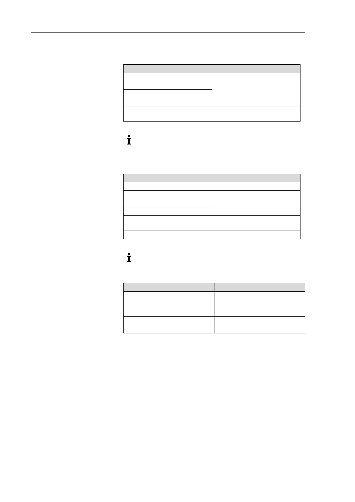
The pumps conform to the Directive 2011/65/EU.
The following harmonized standards have been used:
N 86 K_E
N 86 K_DC
Tab. 2
EU/EC Directives / Standards