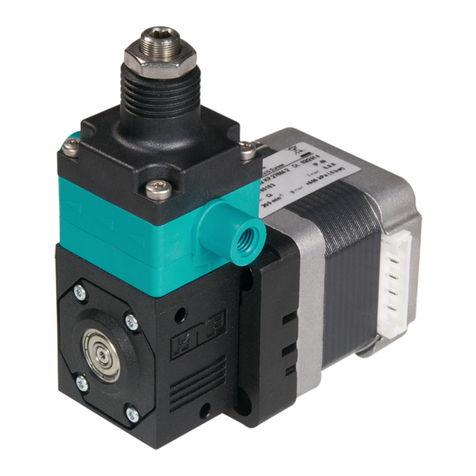
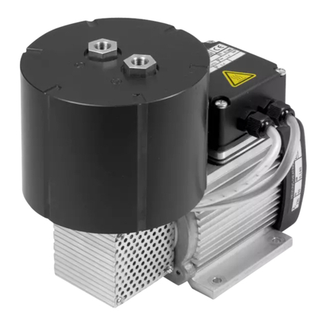
KNF NF 1.100 EX User manual

KNF Flodos AG BA_NF1.100EX_EN_05_152147
English translation of original Operating and Installation Instructions 1
DIAPHRAGM LIQUID PUMP
EXPLOSION-PROOF VERSION
NF 1.100 EX
Pump: II 2G Ex h IIB T5 Gb / Motor: II 2G Ex db IIC T4 Gb
Operating and
Installation Instructions
Read and observe these Operating and
Installation Instructions!
For pumps with a drive motor: be sure to
also read and observe the drive motor's
Operating and Installation Instructions,
which must be considered part of the
pump's Operating and Installation Instruc-
tions.
Due to separate certification of the me-
chanical (pump) and electric (drive motor)
parts, the device has two rating plates.
Each rating plate describes only the part
of the device to which it is applied.
An additional letter prefixing the NF model
code is a country-specific designation,
with no technical relevance.
Contents Page
1. About this document................................................................. 2
2. Use ........................................................................................... 3
3. Safety ....................................................................................... 7
4. Technical data ........................................................................ 10
5. Assembly and function ........................................................... 12
6. Installation and connection..................................................... 13
7. Operation................................................................................ 18
8. Servicing................................................................................. 20
9. Troubleshooting...................................................................... 25
10. Decontamination declaration.................................................. 28
KNF Flodos AG
Wassermatte 2
6210 Sursee, Switzerland
Tel +41 (0)41 925 00 25
Fax +41 (0)41 925 00 35
www.knf-flodos.ch
info@knf-flodos.ch
NF 1.100 KP .27 Ex 230V
- / PMLxxxx / PLxxxx [Ch. 1]
Supply voltage [Ch. 4]
.27 / - [Ch. 5]
KP / KT / TT [Ch. 4]
NF / UNF / JNF
1.100
Ex
TPS 19 ATEX 039495 0007 X

Diaphragm liquid pump NF 1.100 EX About this document
KNF Flodos AG BA_NF1.100EX_EN_05_152147
English translation of original Operating and Installation Instructions 2
1. About this document
1.1. Use of the Operating and Installation Instruc-
tions
The Operating and Installation Instructions are part of the pump.
➔Forward the Operating and Installation Instructions to any
subsequent owners of the pump.
Customer-specific project pumps (pump models which begin with
"PL" or "PML") may differ from the Operating and Installation
Instructions.
➔In the case of project pumps, take note of any additionally
agreed specifications.
The Operating and Installation Instructions apply to the pump
without drive motor.
➔Observe also the drive motor's Operating and Installation
Instructions.
1.2. Symbols and markings
Warning
WARNING
This symbol indicates a potential danger.
It also indicates the possible consequences of failure
to observe the warning. The signal word (e.g. "Warn-
ing") indicates the level of danger.
➔Here you will see actions for avoiding the danger
and potential consequences.
Danger levels
Signal word
Meaning
Consequences if not observed
DANGER
warns of immedi-
ate danger
Consequences include death or
serious injuries and/or serious
property damage.
WARNING
warns of potential
danger
Death or serious injuries and/or
serious damage to property are
possible.
CAUTION
warns of a poten-
tially dangerous
situation
Minor injuries or damage to
property are possible.
Tab. 1
Other information and symbols
➔This indicates an activity (step) that must be carried out.
This indicates the first step of an activity to be carried out. Any
additional steps required are numbered consecutively.
This symbol indicates important information.
Project pumps
Drive motor

Diaphragm liquid pump NF 1.100 EX Use
KNF Flodos AG BA_NF1.100EX_EN_05_152147
English translation of original Operating and Installation Instructions 3
2. Use
2.1. Intended use
The pumps are intended for transferring and metering liquids.
Owner's responsibility
Only install and operate the pumps under the operating parameters
and conditions described in Chapter 4, Technical data, and Section
2.3, Using the pump in a potentially explosive atmosphere.
Only complete pumps may be taken into service.
Before transferring or metering a medium, check whether the
medium can be transferred danger-free in the specific application
case.
Before using a medium, check the compatibility of the materials of
the pump head, pump housing, diaphragm and valves with the
medium.
The temperature of the medium must lie within the permissible
temperature range (see Chapter 4).
The transferred medium should not contain particles as these can
prevent the pump from working correctly. If this cannot be guaran-
teed, a filter < 100 m with sufficiently large filter area must be
used upstream of the pump.
2.2. Improper use
For special modifications outside the standard technical specifica-
tions, please contact your KNF technical adviser.
2.3. Using the pump in a potentially explosive
atmosphere
Only pumps of the appropriate Equipment Category and tempera-
ture class must be operated in potentially explosive atmospheres
(areas).
Such pumps have the following explosion prevention and protec-
tion markings:
Marking
Description
Symbol for explosion-proof pumps
II
Equipment Group (see Section 2.4.1)
2G
Equipment Category (see Section 2.4.2)
h
Type of Protection (see Section 2.4.6)
II A and II B
Explosion Groups (see Section 2.4.4)
T5
Temperature Class (see Section 2.4.3)
Gb
EPL (Equipment Protection Level)
Tab. 2
The explosion prevention and protection markings can also be
found in the following location:
▪Rating Plate
The drive motor of the pump must have at least the same explo-
sion prevention and protection as the pump itself.
Operating parameters and
conditions
Requirements for
transferred medium
Drive motor

Diaphragm liquid pump NF 1.100 EX Use
KNF Flodos AG BA_NF1.100EX_EN_05_152147
English translation of original Operating and Installation Instructions 4
2.4. Explanation of explosion prevention and pro-
tection markings
2.4.1. Equipment groups
Equipment Group 1 applies to equipment for use in the under-
ground operations of mines and any of their surface installations
that may be at risk from methane and/or combustible dust.
Equipment Group II applies to equipment for use in other areas
which may be at risk from explosive atmosphere.
2.4.2. Equipment Categories for gas
The Equipment Category describes the frequency and duration of
occurrence of explosive atmospheres in an area.
Equipment
Category
Description*
Constructional
safety
1
Areas in which hazardous explosive atmospheres are likely to occur
continuously, for long periods or frequently.
Very high
2
Areas in which hazardous explosive atmospheres are likely to occur
occasionally.
High
3
Areas in which it is unlikely that hazardous explosive atmospheres
will occur, or if they do occur, are only likely to do so infrequently and
for a short time.
Normal
Tab. 3 *in accordance with EN 1127-1
2.4.3. Temperature classes
The maximum surface temperature is the highest temperature
reached by one of the pump's surfaces under worst case condi-
tions.
The maximum surface temperature of the pump must always be
lower than the lowest ignition temperature of the gas or vapour/air
mixture in which it is operated.
The maximum surface temperature depends on the design of the
pump, and is shown as a temperature class.
Temperature class
Max. surface tem-
perature [°C]
Ignition temperature
[°C]
T1
≤ 450
> 450
T2
≤ 300
> 300
T3
≤ 200
> 200
T4
≤ 135
> 135
T5
≤ 100
> 100
T6
≤85
> 85
Tab. 4
Equipment Group I
Equipment Group II
Maximum surface
temperature
Ignition temperature
Temperature class

Diaphragm liquid pump NF 1.100 EX Use
KNF Flodos AG BA_NF1.100EX_EN_05_152147
English translation of original Operating and Installation Instructions 5
2.4.4. Explosion Groups
Flammable gases and vapours are classified into explosion groups
(I, IIA, IIB and IIC) and temperature classes. Tab. 5 shows the
classifications of the most common flammable gases and vapours.
T1
T2
T3
T4
T5
T6
I
Methane
–
–
–
–
–
IIA
Acetone
Ethane
Ethyl acetate
Ammonia
Ethyl chloride
Benzene
Acetic acid
Carbon monoxide
Methane
Methanol
Methyl chloride
Naphthalene
Phenol
Propane
Toluene
i-amyl acetate
n-butane
n-butyl alcohol
Cyclohexanone
1,2 dichloroethane
Acetic anhydride
Benzene
Diesel fuel
Aviation turbine
fuel
Heating oils
n-hexane
Acetaldehyde
–
–
IIB
Town gas
Ethylene
Ethyl alcohol
Hydrogen
sulphide
Ethyl ether
–
–
IIC
Hydrogen
Acetylene
–
–
–
Carbon
disulphide
Tab. 5
The classification of gases and vapours into groups according to
explosion group and temperature class applies to both the medium
to be transferred and the environment of the pump.
The pumps must only be used to transfer gases and vapours that
are either not explosive or belong to explosion groups II A or II B
and temperature class T4 (or lower) (shaded area in Tab. 5).
The pumps must only be used in an environment containing an
atmosphere that is either not explosive or belongs to explosion
groups II A or II B and temperature class T4 (or lower) (shaded
area in Tab. 5).
Transferred medium
Pump environment

Diaphragm liquid pump NF 1.100 EX Use
KNF Flodos AG BA_NF1.100EX_EN_05_152147
English translation of original Operating and Installation Instructions 6
2.4.5. Types of protection
Designation
Description
bh
Protection by Control of Ignition Source
h
Constructional safety
kh
Liquid encapsulation
d
Flameproof enclosure
e
Increased safety
i
Intrinsic safety
p
Pressurisation
m
Encapsulation
o
Oil immersion
q
Powder filling
nA
Non-sparking
nC
Several meanings
nR
Vapour proof housing
nL
Energy-limited
(varies between North America and Europe)
nP
Simplified pressurisation
Tab. 6

Diaphragm liquid pump NF 1.100 EX Safety
KNF Flodos AG BA_NF1.100EX_EN_05_152147
English translation of original Operating and Installation Instructions 7
3. Safety
Observe the safety precautions in Chapters
6. Installation and connection, and 7. Operation.
The pumps are built according to the generally recognised rules of
technology and in accordance with the pertinent occupational
safety and accident prevention regulations. Nevertheless, dangers
may occur during their use which may lead to injuries to the user or
others, or to damage to the pump or other property.
Only use the pumps when they are in a good technical and proper
working order, in accordance with their intended use, observing the
safety advice within the Operating and Installation Instructions, at
all times.
Make sure that only trained and instructed personnel or specially
trained personnel work on the pumps. This especially applies to
assembly, connection and servicing work.
Make sure that all personnel have read and understood the Oper-
ating and Installation Instructions, and in particular the "Safety"
chapter.
Observe the accident prevention and safety regulations when
performing any work on the pump and during operation.
When transferring dangerous medium, observe the safety regula-
tions for handling such medium.
Always ensure adherence to all information stickers on the pumps,
such as flow direction arrows and rating plates, and keep stickers
in legible condition.
All replacement parts should be properly stored and disposed of in
accordance with the applicable environmental protection regula-
tions. Ensure adherence to the pertinent national and international
regulations. This especially applies to parts contaminated with toxic
substances.
Dispose of all packaging in an environmentally-appropriate
manner. The packaging materials are recyclable.
Dispose of end-of-life equipment in an environmentally
friendly manner. Use appropriate waste collection systems
for the disposal of end-of-life equipment. Used pumps
contain valuable recyclable materials.
The pumps conform to the safety requirements regarding electro-
magnetic compatibility in Directive 2004/108/EC.
For the purposes of the Machinery Directive 2006/42/EC, pumps
are “partly completed machinery", and are therefore to be regarded
as not ready for use. Partly completed machinery may not be
commissioned until such time as it has been determined that the
machine in which the partly completed machinery is to be assem-
bled conforms to the provisions of the Machinery Directive
Personnel
Working in a
safety-conscious manner
Handling dangerous medium
Notes
Environmental protection
Disposal
EU directives/standards

Diaphragm liquid pump NF 1.100 EX Safety
KNF Flodos AG BA_NF1.100EX_EN_05_152147
English translation of original Operating and Installation Instructions 8
2006/42/EC. The essential requirements of Annex I of Directive
2006/42/EC (general principles) are applied and observed.
The pumps comply with Directive 2014/34/EU concerning equip-
ment and protective systems for intended use in explosive atmos-
pheres, and with the standards ISO 80079-36 and ISO 80079-37
for ex areas.
The "Directives for the prevention of risks from explosive atmos-
pheres with a collection of examples –explosion prevention and
protection directives –(EX-RL)" should be observed when classify-
ing a pump environment in an explosion-proof area.
In special cases or where there is doubt when defining potentially
explosive atmospheres, notify the supervisory authorities and ask
them to decide.
All repairs to the pump(s) must be carried out by the relevant KNF
Customer Service team.
Only use genuine parts from KNF for servicing work.
Safety concept
A risk analysis was carried out in accordance with EN 1127-1.
Ignition sources
If the pump compresses against the maximum permissible operat-
ing pressure, the temperature of the head will not exceed the
maximum surface temperature because the head is able to transfer
heat to its environment. The pump's environment must therefore
be adequately ventilated.
The projected surface area of the non-conductive parts which may
become electrostatically charged is less than 100cm2. The total
surface area of electrically insulated metal disks is very small, in
addition to which the screw heads are countersunk in the pump
head. As a result there should be no risk of ignition from the elec-
trostatically chargeable parts.
As a result of the material used inside the pump, the possibility that
critical material combinations may come into contact is excluded.
In addition, these are mounted pumps, which should preferably be
installed in housings and are made of plastic.
The nuts and bolts used are made of stainless steel, so contact
with critical materials is unlikely.
EU directives/standards
Customer service and
repairs
Risk analysis
Heating of head
Electrostatic
charge
Mechanically
generated sparks

Diaphragm liquid pump NF 1.100 EX Safety
KNF Flodos AG BA_NF1.100EX_EN_05_152147
English translation of original Operating and Installation Instructions 9
Rupturing of the diaphragm and separation of the steel portion is
unlikely. However, this would be noticed at once because flow rate
would fall considerably. In the event of damage, the loose steel
component would be channelled by the pump housing. Even in the
event of a malfunction, no sparks would therefore be generated
mechanically.
Replacing the diaphragm is described in Chapter 8, Servicing.
Have ball bearings replaced in accordance with the servicing
schedule in Chapter 8.1.
Rupturing of diaphragm
Failure of ball bearings

Diaphragm liquid pump NF 1.100 EX Technical data
KNF Flodos AG BA_NF1.100EX_EN_05_152147
English translation of original Operating and Installation Instructions 10
4. Technical data
Pump materials
The pump type KP stands for:
Assembly
Material1)
Pump head*
PP
Valve plate
EPDM
Diaphragm
PTFE-coated
Resonating diaphragm
PTFE
Diaphragm. 27
EPDM
Tab. 7 1) according to DIN ISO 1629 and 1043.1
The pump type KT stands for:
Assembly
Material1)
Pump head*
PP
Valve plate
FFKM
Diaphragm
PTFE-coated
Resonating diaphragm
PTFE
Diaphragm. 27
FFKM / FKM
Tab. 8 1) according to DIN ISO 1629 and 1043.1
The pump type TT stands for:
Assembly
Material1)
Pump head*
PVDF
Valve plate
FFKM
Diaphragm
PTFE-coated
Resonating diaphragm
PTFE
Diaphragm. 27
FFKM / FKM
Tab. 9 1) according to DIN ISO 1629 and 1043.1
* The pump head (Fig. 1) comprises a connecting plate and an intermedi-
ate plate
Hydraulic ratings
Parameter
Value
Flow rate [l/min] 1), 2)
1.0
Max. permissible pressure NF 1.100 [bar g]
4
Suction head [mWG]
2.5
Tab. 10
1) Measured with water at 20°C / at atmospheric pressure
2) Flow rates may vary from the values shown, depending on fluid viscosi-
ty, pump head material and the hoses / hose connectors used.
Hydraulic connections
Parameter
Value
NF 1.100
G 1/8"
UNF 1.100
NPT 1/8"
Recommended hose size ID [mm]
8
Tab. 11

Diaphragm liquid pump NF 1.100 EX Technical data
KNF Flodos AG BA_NF1.100EX_EN_05_152147
English translation of original Operating and Installation Instructions 11
Specifications NF 1.100 Ex
Motor voltage
Value
Voltage [V]
110 / 115 / 230
Speed [RPM]
< 3500
Protection class [IP]
66
Weight1) [g]
6000
Tab. 12
1) The weight may differ slightly from the stated value, depending on the
version.
Other parameters
Parameter
Value
Permissible
ambient temperature range (°C)
+ 5 to + 40
Permissible medium temperature
range (°C)
+ 5 to + 40
Permissible kinematic viscosity of
medium [cSt]
≤150
Tab. 13
Pump rating plate
1
2
3
4
5
6
7
8
9
10
1 Project number
2 Pump type
3 Company number (3 = KNF
Flodos) and serial number
4 Permissible ambient temper-
ature (see also Tab. 14)
5 Permissible speed
6 Date of manufacture
(Month/Year)
7 Explosion prevention and
protection marking
8 Certificate number
9 Permissible operating
pressure
10 Flow rate (see also Tab. 11)

Diaphragm liquid pump NF 1.100 EX Assembly and function
KNF Flodos AG BA_NF1.100EX_EN_05_152147
English translation of original Operating and Installation Instructions 12
5. Assembly and function
Assembly
1Condenser
2Outlet
3Pump head
4Inlet
5Motor
6Motor base plate
7Pump rating plate
8Motor rating plate
Fig. 1: Diaphragm liquid pump
1Outlet valve
2Inlet valve
3Working chamber
4Diaphragm
5Eccentric
6Connecting rod
7Pump drive
Fig. 2: Operating principle
The diaphragm liquid pumps are based on reciprocating displace-
ment pump technology. The elastic diaphragm (4) is moved up and
down by the eccentric (5) and the connecting rod (6). In the down-
ward stroke it aspirates the medium to be transferred via the inlet
valve (2). In the upward stroke, the diaphragm pushes the medium
out of the pump head via the outlet valve (1). The diaphragm
hermetically seals off the working chamber (3) from the pump
drive (7).
NF 1.100 version (fixed flow rate)
This pump type represents this product in its simplest form and
transfers medium at the fixed flow rate.
NF 1.100 .27 version (fixed flow rate with overpressure limit-
ing)
If the diaphragm liquid pump is operating against a closed system,
the delivery pressure quickly exceeds the maximum permissible
values. To prevent this happening, an overflow valve is integrated
in the top part of the pump head. If the pressure exceeds the
variable limit range (min. 1.5 to max. 4.0 barg), the valve opens
and the liquid circulates from the pressure side to the suction side
via an internal bypass system. This prevents any further rise in
pressure.

Diaphragm liquid pump NF 1.100 EX Installation and connection
KNF Flodos AG BA_NF1.100EX_EN_05_152147
English translation of original Operating and Installation Instructions 13
6. Installation and connection
Only install pumps under the operating parameters and conditions
described in Chapter 4, Technical data, and in Section 2.3, Using
the pump in a potentially explosive atmosphere.
Observe the safety precautions (see Chapter 3).
6.1. Installation
➔Before installation, store the pump at the installation location to
bring it up to ambient temperature.
➔Mounting dimensions (see Fig. 3)
NF1.100 Ex
NF1.100.27 Ex
Fig. 3: Mounting dimensions NF1.100 Ex
➔For pumps with fan: When installing the pump, make sure that
the motor’s fan can draw in an adequate amount of cooling air.
➔Make sure that the installation location is dry and the pump is
protected against water in the form of rain, spray, splashes and
drips.
➔Protect the pump against dust.
➔Protect the pump against vibration and impact.
Mounting dimensions
Cooling air supply
Installation location

Diaphragm liquid pump NF 1.100 EX Installation and connection
KNF Flodos AG BA_NF1.100EX_EN_05_152147
English translation of original Operating and Installation Instructions 14
➔Generally speaking, the pump can be mounted in any orienta-
tion. For maximum precision and rapid venting, install pump as
shown in the illustration (Fig. 4).
Fig. 4: optimum installation position / horizontal
➔KNF recommends mechanically decoupling the pump from the
piping system. This can be achieved with flexible hoses or
pipes, for example. This prevents any oscillations of the pump
being transferred to the system.
WARNING
Danger of injury during operation
➔Take protective measures against touching parts
which are energised (live), such as electrical
connections or windings.
➔Take protective measures against touching
moving parts (e.g. fan).
Danger of damaging the pump during operation
➔Take protective measures to ensure that no
foreign objects can get into the pump (see pro-
tection class).
6.2. Electrical connection
WARNING
Danger of explosion as a result of incorrect electrical
connection
May cause severe injuries or death
➔Only connect pump/motor if it is safe to operate
them in the explosive atmosphere concerned.
➔Observe the Operating and Installation Instruc-
tions and the following requirements.
DANGER
Danger of electric shock, danger of death
➔Only have the pump connected by an authorized
specialist.
➔Only have the pump connected when the power
supply is disconnected.
Installation position
Decoupling
Contact and foreign-object
protections

Diaphragm liquid pump NF 1.100 EX Installation and connection
KNF Flodos AG BA_NF1.100EX_EN_05_152147
English translation of original Operating and Installation Instructions 15
➔When connecting the device to a power source, the relevant
norms, directives, regulations and technical standards must be
observed.
WARNING
Danger of explosion as a result of electrostatic
charge
➔Connect the pump in such a way as to prevent
the risk of ignition by electrostatic charge.
➔Carefully earth the pump.
➔Observe the Operating and Installation Instructions for the
drive motor.
➔Only the electrical equipment required to operate the pump
should be placed with it in potentially explosive atmospheres.
➔Take precautions to protect against lightning.
Make sure that
➔all electrical equipment meets the requirements for the area
concerned (e.g. Emergency Stop switch, overcurrent release).
➔the information on the drive motor's rating plate matches the
nominal values of the electrical power supply. Voltage and fre-
quency values must comply with the mains data (tolerance:
5%).
➔the drive motor is protected against excessive heating by
means of thermal/electromagnetic overcurrent releases, such
as motor protective circuit switches in accordance with VDE
0660.
➔the overcurrent release has been set to the rated current on
the rating plate and the tripping response curve.
➔safety devices have been fitted to ensure that the motor is
protected even if a phase conductor fails.
➔protection and overcurrent releases are set in such a way that
after an item of equipment is triggered the drive motor is dis-
connected from the power supply (all poles). The release must
not switch itself back on.
➔precautions against atmospheric discharge (lightning) have
been taken.
➔all electrically conductive parts are earthed. Make sure that
removable components such as safety devices, coupling ele-
ments etc. do not interrupt earth continuity.
➔For circuit breakers and relays with current-dependent delayed
tripping.
Drive motor
Potentially explosive
atmospheres

Diaphragm liquid pump NF 1.100 EX Installation and connection
KNF Flodos AG BA_NF1.100EX_EN_05_152147
English translation of original Operating and Installation Instructions 16
Connecting the pump
Connect individual conductors of the motor supply cable to the
terminal bar. Tighten the clamping (pressure) screw of the
screwed cable gland to a torque of 2.5 Nm.
Carefully inspect the marked earthing screw with non-rotating
clamp inside the motor terminal box.
Connect earthing equipment conductor to earthing screw as
shown in Fig. 5.
Fig. 5: Connecting the earthing
equipment conductor

Diaphragm liquid pump NF 1.100 EX Installation and connection
KNF Flodos AG BA_NF1.100EX_EN_05_152147
English translation of original Operating and Installation Instructions 17
6.3. Hydraulic connection
➔Only connect components to the pump that are designed to
handle the hydraulic data of the pump (see
Chapter 4, Technical data).
➔Only use hoses that are suitable for the maximum operating
pressure of the pump (see Chapter 4).
➔Only use hoses that are sufficiently chemically resistant to the
liquids being transferred.
➔Protect the pump with a pressure relief device between the
outlet side of the pump and the first shutoff valve.
WARNING
Danger of explosion if the medium mixes with the
environment during pressure relief
➔Make sure that the medium cannot combine with
the pump's environment during pressure relief.
➔During pressure relief, make sure that the medi-
um is captured in a suitable container in such a
way that there is no danger of explosion.
6.3.1. Connecting the pump
Arrows on the pump head indicate the flow direction.
Remove the protective caps from the connections.
Connect the suction and pressure lines.
Keep the suction line as short as possible in order to keep the
priming process as brief as possible.
If the pump is used to build up pressure, make sure that all
transition joints between hose and pump are secure in order to
ensure that the hoses cannot come off the hose connectors.
Check that the hoses and transition joints are fitted correctly
and securely.
Check that the system is leak-tight.
Connected
components
Hoses
Pressure relief device

Diaphragm liquid pump NF 1.100 EX Operation
KNF Flodos AG BA_NF1.100EX_EN_05_152147
English translation of original Operating and Installation Instructions 18
7. Operation
➔Only operate the pumps under the operating parameters and
conditions described in Chapter 4, Technical data, and in Sec-
tion 2.3, Using the pump in a potentially explosive atmosphere.
➔Make sure that the pumps are being used properly (see Chap-
ter 2.1).
➔Avoid improper use of the pumps (see Chapter 2.2).
➔Observe the safety precautions (see Chapter 3).
➔The pumps are components that are intended to be incorpo-
rated into another machine. Before putting them into service it
must be established that the machinery or systems in which
they are installed meet the relevant regulations.
CAUTION
Risk of burning
The drive heats up.
➔Avoid contact with the pump drive
➔Avoid contact with flammable materials.
Excessive pressure and the inherent dangers thereof can be
prevented by placing a bypass line with a pressure relief valve
between the pressure and suction side of the pump. For further
information, contact your KNF technical adviser (Telephone
number: see first page).
WARNING
Risk of explosion as a result of high ambient tem-
perature
➔Monitor ambient temperature (heat of compres-
sion, motor heat).
➔Provide an adequate supply of cooling air.
➔If the pump stops running, restore the system to normal at-
mospheric pressure.
Check the pump regularly for external damage or leaks.
Duty cycle / short cycle operation
KNF pumps are designed for continuous operation.
If the pump is operated with short cycles in your application,
please contact a KNF technical adviser for further information
(Telephone number: see first page).
Switching on the pump
➔In order to ensure that the pump starts every time, make sure
that counterpressure is reduced to an acceptable level before
start-up. This should also be done during operation after a brief
power cut.
Pump standstill
Check the pump
Short cycle operation

Diaphragm liquid pump NF 1.100 EX Operation
KNF Flodos AG BA_NF1.100EX_EN_05_152147
English translation of original Operating and Installation Instructions 19
For more specific information contact your KNF technical
adviser.
Switching off the pump
➔KNF recommends: If transferring aggressive liquids, the pump
should be flushed thoroughly prior to switch off (see Chapter
8.2.1), as this will help to lengthen the service life of the dia-
phragm.
➔Restore the system to normal atmospheric pressure (release
hydraulic pressure in pump).
Flow rate NF 1.100
Fig. 6: Flow rate of the pump NF 1.100

Diaphragm liquid pump NF 1.100 EX Servicing
KNF Flodos AG BA_NF1.100EX_EN_05_152147
English translation of original Operating and Installation Instructions 20
8. Servicing
8.1. Servicing schedule
Component
Servicing interval
Pump
-Regular inspection for external
damage or leaks
Pump head
-Clean if the flow rate decreases, the
pump does not work or no vacuum
is created (Chapter 8.2)
Diaphragm, valve
plates and seals
-Change as soon as pumping capac-
ity decreases, preferably sooner
Tab. 14
Standard regulations dictate that the bearings in the pump be
replaced at regular intervals as a precautionary measure.
Depending on the pressure in your system the recommended time
interval will vary - see table below.
Please contact your local KNF Company to discuss the best way of
implementing this service.
Operating pressure [bar g]
Replacement interval
p ≤ 3
20’000 operating hours
3 < p ≤ 4
15’000 operating hours
Tab. 15
8.2. Cleaning
WARNING
Health hazard due to dangerous substances in the
pump
Depending on the medium transferred, caustic burns
or poisoning are possible.
➔Wear protective clothing if necessary, e.g. pro-
tective gloves.
➔Flush the pump with a neutral liquid and pump
empty.
8.2.1. Flushing the pump
➔If transferring aggressive medium, KNF recommends flushing
the pump with a neutral fluid under atmospheric conditions for
a few minutes before switching off in order to extend the ser-
vice life of the diaphragm.
Ball bearings
Information on procedure
Table of contents
Other KNF Water Pump manuals
Popular Water Pump manuals by other brands

Viessmann
Viessmann Solar-Divicon PS10 Installation and service instructions

Lumax
Lumax LX-1311 Operational manual

Pentair
Pentair Nocchi MCP 4 Use and maintenance manual

Almatec
Almatec Quattroflow 1200SU Operating and installation instructions

Fluke
Fluke P5510 user manual

Nibe
Nibe VVM 225 Service instruction

K2 Pumps
K2 Pumps WPD07502K owner's manual

PHA
PHA VERSA-MATIC E1 Service & operating manual

Generac Power Systems
Generac Power Systems C20 owner's manual

Wayne
Wayne 330600-001 Operating instructions and parts manual

Blue Angel
Blue Angel EC50 Operating instructions and parts manual
Kremlin-Rexson
Kremlin-Rexson Standard 65-130 manual