KNF SCC 950 User manual

KNF 304771-304773 07/18
Translation of original Operating Instructions, English
Operating Instructions
Read and observe these Operating Instructions!
Vacuum pump system
SCC 950
KNF Neuberger GmbH
Alter Weg 3
79112 Freiburg
Germany
Tel. +49 (0)7664 / 5909-0
Fax +49 (0)7664 / 5909-99
E-Mail: inf[email protected]
www.knf.de

Translation of original Operating Instructions, English, KNF 304771-304773 07/18
Items included in delivery:
Vacuum pump system, including two hand terminals (bat-
teries included)
Separate charging station for second hand terminal
Bracket to attach the charging station and second hand
terminal to the vacuum pump system
Coated collection flasks (2 x)
Flask clips (2 x)
Power cable
USB cable for connecting vacuum pump system to PC
Power supply for hand terminal
Operating instructions
Abbreviated instructions
CD with digital operating instructions and software for op-
erating the vacuum pump system with a PC
Transportation protection
Hand terminal 1 of the vacuum pump system is secured at the
factory in order to prevent damage during transportation.
The transportation protection must be removed
before hand
terminal 1 can be removed. Refer to Chapter
6 Setup and
connection.
Hand terminal 2 is enclosed without a transport securing
device.

Vacuum pump system SCC 950 Table of Contents
Translation of original Operating Instructions, English, KNF 304771-304773 07/18
Content Page
1. About this document 4
1.1. Use of the Operating Instructions 4
1.2. Symbols and markings 4
2. Use 5
2.1. Intended use 5
2.2. Improper use 6
3. Safety 7
4. Technical data 9
4.1. Vacuum pump system 9
4.2. Hand terminal of the vacuum
pump system 11
4.3. Software 12
5. Assembly and functions 13
5.1. SCC 950 13
5.1.1.Assembly of the vacuum pump
system 13
5.1.2.Vacuum pump system functions14
5.1.3.Hand terminals 16
5.2. Pump 17
5.3. Gas ballast 18
6. Setup and connection 19
6.1. Installation 19
6.2. Connections 22
7. Operation 23
7.1. Initial start-up 23
7.2. Stopping operation 26
8. Operating the vacuum pump system27
8.1. Hand terminal 27
8.1.1.General functions and displays 27
8.1.2.Operation 29
8.1.3.Changing batteries on the hand
terminal 35
8.2. Operation without hand terminal 36
8.3. Software 36
9. Servicing 37
9.1. Servicing schedule 37
9.2. Cleaning 37
9.2.1.Rinsing the vacuum pump
system 37
9.2.2.Cleaning the vacuum pump
system 37
9.2.3.Emptying collection flask on the
suction and pressure sides 37
9.3. Replacing the diaphragms and
valve plates 39
9.3.1.Removing the pump 40
9.3.2.Overview of pump parts 41
9.3.3.Disassembling head connection42
9.3.4.Disassembling pump heads 42
9.3.5.Replacing the diaphragms and
valve plates 44
9.3.6.Assembling heads and head
connection 45
9.3.7.Final steps 46
10. Troubleshooting 47
11. Spare parts and accessories 52
11.1. Spare parts 52
11.2. Accessories 53
12. Returns 54
13. Health and safety clearance and
decontamination form 55

About this document Vacuum pump system SCC 950
4 Translation of original Operating Instructions, English, KNF 304771-304773 07/18
1. About this document
1.1. Use of the Operating Instructions
The Operating Instructions are an integral part of the vacuum
pump system.
Carefully study the Operating Instructions before operating the
vacuum pump system.
Always keep the Operating Instructions handy in the work
area.
Forward the Operating Instructions to any subsequent
owners of the vacuum pump system.
Customer-specific vacuum pump systems (model designations
which begin with "PJ" or "PM") may differ from the Operating
Instructions.
In the case of custom systems, take note of any additionally
agreed specifications.
Compliance with the Operating Instructions is essential for safe
and reliable operation of the vacuum pump system. Failure to
do so
may result in damage or injury.
1.2. Symbols and markings
Warning
WARNING
This symbol indicates a danger statement.
It also indicates the possible consequences of failure
to observe the warning. The signal word (i.e. “War
n-
ing”) indicates the level of danger.
Here you will see actions for avoiding the danger
and potential consequences.
Danger levels
Signal word
Meaning
Consequences if not observed
DANGER
warns of immedi-
ate danger
Consequences include death or
serious injuries and/or serious
property damage.
WARNING
warns of potential
danger
Death or serious injuries and/or
serious property damage are
possible.
CAUTION
warns of a poten-
tially dangerous
situation
Minor injuries or damage to
property are possible.
Tab. 1
Other information and symbols
This indicates an activity (step) that must be carried out.
1. This indicates the first step of an activity to be carried out. Any
additional steps are numbered consecutively.
This symbol indicates important information.
Custom systems

Vacuum pump system SCC 950 Use
Translation of original Operating Instructions, English, KNF 304771-304773 07/18 5
2. Use
2.1. Intended use
The SCC 950 vacuum pump system is designed for use in chemi-
cal, pharmaceutical, and biological laboratories. It is designed
exclusively to transfer gases and vapors.
Make sure that the installation location is dry and that the system is
protected against water in the form of rain, spray, splashes and
drips.
The vacuum pump system is solely for use in indoor areas.
Owner's responsibility
Only install and operate the vacuum pump system under the
operating parameters and conditions described in Chapter 4,
Technical data.
Protect the vacuum pump system against humidity.
Before using a medium, check the compatibility of the materials of
the pump head, diaphragms, valves, seals and hoses with the
medium.
Before transferring a medium, check whether the medium can be
transferred safely.
Only transfer gases that remain stable under the pressures and
temperatures occurring in the vacuum pump system.
The high-performance condenser may be used only at the pump
outlet; there is a risk of implosion if it is used at the pump inlet.
Make sure the tubes for gas and cooling medium are correctly
assigned on the high-performance condenser. Inlets and outlets of
the gas connections must not be confused.
Laboratory equipment or additional components connected to the
vacuum pump system have to be suitable for use with the pneu-
matic capabilities of the vacuum pump system (see Chapter 4,
page 9).
Operating parameters and
conditions
Requirements for media
to be transferred
High-performance condenser
Accessories

Use Vacuum pump system SCC 950
6 Translation of original Operating Instructions, English, KNF 304771-304773 07/18
2.2. Improper use
The vacuum pump system must not be operated in potentially
explosive atmospheres.
The vacuum pump system is not suitable for transferring dust.
The vacuum pump system is not suitable for transferring liquids.
The vacuum pump system must not be used if the entry of air or
gas into the vacuum pump system during venting (ventilation
valve) or an open gas ballast valve could result in the creation of
reactive, explosive or otherwise hazardous mixtures (e.g. with the
medium).
The vacuum pump system must not be used to create vacuum and
pressure simultaneously.
Never apply positive pressure to the suction side of the vacuum
pump system.

Vacuum pump system SCC 950 Safety
Translation of original Operating Instructions, English, KNF 304771-304773 07/18 7
3. Safety
The vacuum pump system is built according to the generally rec-
ognized rules of technology and in accordance with the pertinent
occupational safety and accident prevention regulations. Neverthe-
less, potential dangers during use can result in injuries to the user
or others, or in damage to the vacuum pump system or other
property.
Only use the vacuum pump system in a good technical and proper
working order, in accordance with its intended use, with awareness
of safety and potential hazards, and observing the advice within
the Operating Instructions, at all times.
Make sure that only trained and instructed personnel or specially
trained personnel work on the vacuum pump system. This espe-
cially applies to assembly, connection and servicing work.
Make sure that the personnel have read and understood the Oper-
ating Instructions, especially the "Safety" chapter.
Ensure adherence to all pertinent accident prevention and safety
regulations when working on and operating the vacuum pump
system.
Do not subject parts of the body to vacuum.
Open housing parts with notice sticker (see Fig. 1) only after sepa-
rating mains plug from power source.
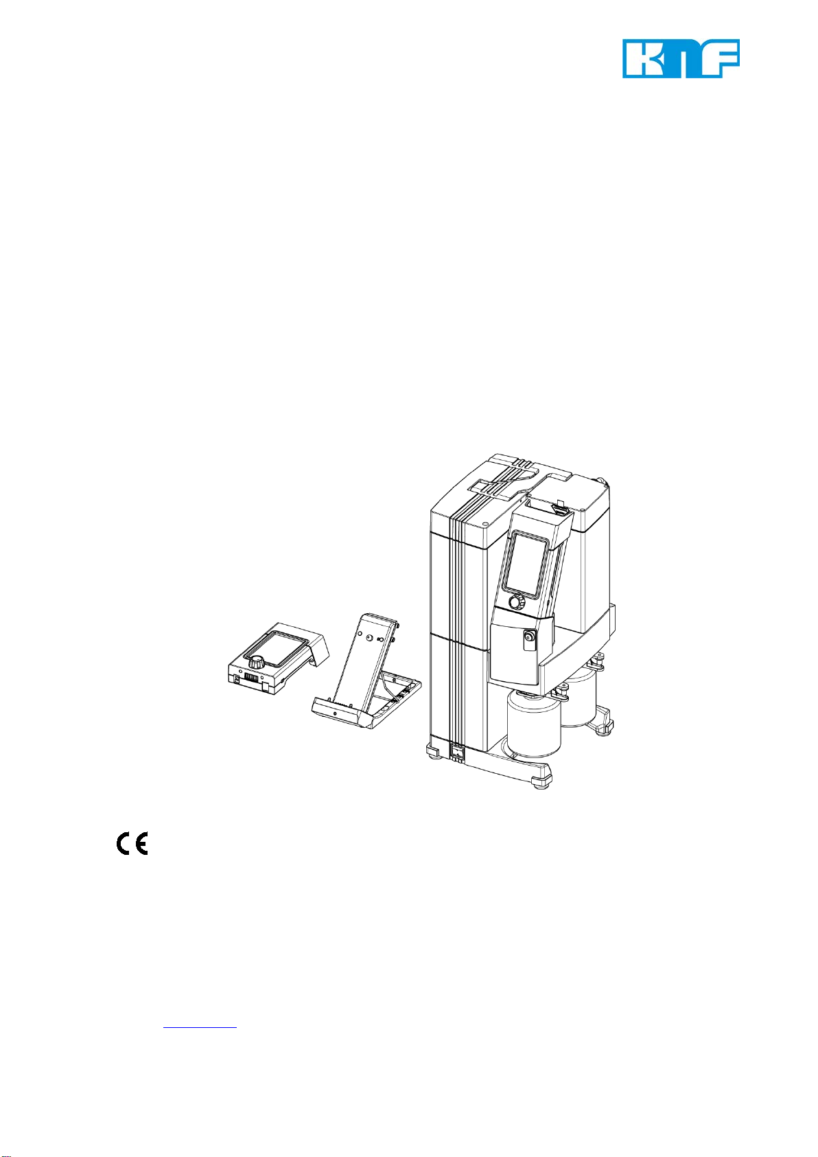
Ensure that personnel check before each use of the SCC 950
vacuum pump system that they have the correct hand terminal for
the vacuum pump system. The vacuum pump system is equipped
with a paging function for this purpose (see Paging the vacuum
pump system, page 34).
When transferring dangerous media, observe the safety regula-
tions for handling such media.
Be aware that the vacuum pump system is not designed to be
explosion-proof.
Make sure that the temperature of the medium is always sufficient-
ly below its ignition temperature in order to avoid ignition or explo-
sion. This also applies to unusual operating situations.
Note that the temperature of the medium increases when the pump
compresses the medium.
Hence, make sure that the temperature of the medium is sufficient-
ly below its ignition temperature, even when it is compressed to the
maximum permissible operating pressure of the vacuum pump
system. The vacuum pump system's maximum permissible operat-
ing pressure is specified in the Technical data (see Chapter 4,
page 9).
Personnel
Working in a
safety-conscious manner
Fig. 1: Notice sticker
Using the right
hand terminal
for the vacuum pump system
Handling dangerous media
Handling flammable
media

Safety Vacuum pump system SCC 950
8 Translation of original Operating Instructions, English, KNF 304771-304773 07/18
Consider any external sources of energy, such as sources of
radiation, that could additionally heat the medium.
In case of doubt, consult KNF customer service.
When ventilating the vacuum pump system with air or inert gas, be
sure to prevent the formation of reactive or explosive media. The
maximum permissible operating pressure at the ventilation connec-
tion (Fig. 2/18, p. 13) is 0.1 bar g.
All replacement parts should be properly stored and disposed of in
accordance with the applicable environmental protection regula-
tions. Ensure adherence to the pertinent national and international
regulations. This applies especially to parts contaminated with toxic
substances.
The SCC 950 vacuum pump system conforms to the Directive
2011/65/EU (RoHS2).
The SCC 950 vacuum pump system conforms to the safety regula-
tions of Directive 2014/30/EU concerning Electromagnetic Compat-
ibility and Directive 2006/42/EC concerning Machinery. The follow-
ing harmonized standards are met:
DIN EN 61010-1
DIN EN 61326-1 – Class A
DIN EN 50581
In accordance with IEC 664 the systems conforms to:
Overvoltage category II
Pollution degree 2
All repairs to the vacuum pump system must be carried out by the
responsible KNF Customer Service team.
Housings with live parts may be opened by technical personnel
only.
Use only genuine parts from KNF for servicing work.
Ventilating the vacuum pump
system
Environmental protection
Standards
Customer service and
repairs

Vacuum pump system SCC 950 Technical data
Translation of original Operating Instructions, English, KNF 304771-304773 07/18 9
4. Technical data
4.1. Vacuum pump system
Materials for parts in contact with the medium
Pump head
PPS
Interconnection parts
PPS
Diaphragms
PTFE-coated
Valve plates
FFPM
Flat seals
FFPM
O-rings, green
FPM
O-rings, black
FFPM
Hose connector gas inlet
PVDF
Hose connector gas outlet
PP/PVDF
Hose connector inert gas
connection
Brass, nickel-plated
Hoses
Norprene®
Adapter separator
PP
Adapter control unit
PPS
Adapter connector
PP
Pressure transducer
Ceramic / 1.4404
Ventilation valves/gas ballast
valve:
Anchor seal
O-ring
Tube
FFPM
FPM
1.4301
Vacuum valve
FFPM
Non-return valve
FFPM
Pneumatic performance
Max. permissible
operating pressure [bar g]
0
Ultimate vacuum [mbar abs.]
≤ 2 mbar
≤ 4 mbar with open gas ballast
Flow rate at atm. pressure
[l/min]*
Approx. 50 (adjustable)
Max. permissible pressure at
inert gas connection [bar g]
0.1
Ambient and media temperature
Permissible media and
ambient temperature
+10°C to + 40°C
* liters in standard state (1013 mbar at 0°C)
Tab. 2 (1st part)

Technical data Vacuum pump system SCC 950
10 Translation of original Operating Instructions, English, KNF 304771-304773 07/18
Other parameters
Vacuum connection and
gas outlet
For hose ID 10 mm
Ventilation connection
For hose ID 4 mm
Weight [kg]:
(including hand
terminals)
Approx.18.2
Dimensions W x H x D [mm]:
- with charging station at-
tached
- without charging station
attached
353 x 487 x 376
246 x 487 x 376
Maximum permissible ambient
relative humidity
(not condensing)
80% for temperatures up to
31°C, decreasing linearly to 50%
at 40°C
Maximum altitude of installa-
tion [m above sea level]
2000
Coolant supply parameters (high-performance condenser)
Permissible pressure [bar g]
3
Permissible temperature
- 15 °C to + 20 °C
Coolant connections on high-
performance condenser
For hose ID 8 mm
Coolant-coated surface [cm2]
Min. 470
Electrical data of vacuum pump system
Nominal voltage** [V]
100-240 +/- 10%
Frequency [Hz]
50-60
Maximum operating current [A]
1.7
Max. power consumption [W]
150
Protection class
IP20
Vacuum pump system fusing
[A]
2 x T2.5
Drive motor fusing
Electronic overcurrent protection
Tab. 2 (2nd part) ** Automatic mains power adjustment
The pump of the vacuum pump system is supplied by a univer-
sal power supply with integ
rated overload protection. It is
protected against overheating by a temperature sensor on the
motor board and equipped with overcurrent protection.
If one of these safety functions is triggered, the pump will be
shut down and must be manually reset, as fol
lows:
Separate vacuum pump system from the mains.
Remove the cause(s) of the fault before restarting.

Vacuum pump system SCC 950 Technical data
Translation of original Operating Instructions, English, KNF 304771-304773 07/18 11
4.2. Hand terminal of the vacuum pump system
Dimensions: W x H x D [mm]
91 x 190 x 65
Weight [kg]
0.5
Operating voltage [V DC]
24
Operating current [A]
1
Wireless connection's frequen-
cy band [GHz]
2.4
Wireless range
Approx. 50 m without obstacles
Approx. 10 m through walls
Power supply
Via integrated batteries or
supplied power supply unit;
cable length approx. 1.50 m,
with adapter set:
EURO / UK / USA / AUS
DC charging socket
External diameter: 6.3 mm
Inside diameter: 2 mm
Batteries
4 x AA 1.2 V 2600 mAh; quick-
charge capable; see spare
parts list in Chapter 11
Battery service life*
Up to 12 hours, depending on
number of entries and data
transmission
Charging time*
about 7 h
Tab. 3 * Applies to standard included batteries
When charging the hand terminals of the SCC 950 vacuum
pump system, use only the original power supply from KNF.
Several SCC 950 vacuum pump systems can be operated
simultaneously within the range of the wireless connection
using the associated hand terminals.
The wireless connection between the hand terminal and the
SCC 950 vacuum pump system is robustly compatible with cell
phones and Bluetooth devices in the immediate area.

Technical data Vacuum pump system SCC 950
12 Translation of original Operating Instructions, English, KNF 304771-304773 07/18
4.3. Software
The USB connection between the PC and the SCC 950 vacuum
pump system is operated as an RS232 interface. Accordingly, in
the operating system it is managed as an additional COM connec-
tion and can be addressed with conventional terminal software.
Please see the delivered CD for information on operating the
vacuum pump system via software.

Vacuum pump system SCC 950 Assembly and functions
Translation of original Operating Instructions, English, KNF 304771-304773 07/18 13
5. Assembly and functions
5.1. SCC 950
5.1.1. Assembly of the vacuum pump system
1
Carrying handle
2
Holder for hand terminal 1
for transportation
3
High-performance conden-
ser
4
Hand terminal 1
(removable; signals trans-
mitted wirelessly)
5
Holder for
hand terminal 1
6
Gas ballast switch
7
Flask clips for 8and 9
8
Pressure-side condensate
collection flask (coated)
9
Suction-side condensate
collection flask (coated)
10
Base
11
Power switch
12
Charging station for hand
terminal 2
13
Hand terminal 2
14
Top fan
15
Control module
16
Connection for ventilating
vacuum chamber 1
17
Connection for vacuum
chamber 1 (gas inlet)
18
Connection for vacuum
chamber 2 (gas inlet)
19
Connection for ventilating
vacuum chamber 2
20
Bottom fan
21
Coolant valve connection
22
USB port for connecting
vacuum pump system to
PC
23
Fuse drawer
24
Mains plug connection
25
Coolant connection on
high-performance conden-
ser (discharge)
26
Coolant connection on
high-performance conden-
ser (feed)
27
Gas outlet
Fig. 2: SCC 950 vacuum pump system

Assembly and functions Vacuum pump system SCC 950
14 Translation of original Operating Instructions, English, KNF 304771-304773 07/18
The SCC 950 vacuum pump system uses a pump to generate a
vacuum with which two separate processes can be controlled with
the help of the two hand terminals (Fig. 2/4and 13, p. 13) or a PC.
The control module (15) contains two vacuum (17 and 18) and two
ventilation connections (16 and 19). Integrated non-return valves in
the vacuum connections stop the two processes from affecting
each other. The integrated pressure sensors each determine the
current process pressure.
Collection flask (9) collects on the suction side of the pump parti-
cles and drops that were, contrary to the requirements of the
pump, suctioned from the vacuum chamber. The collection flask is
coated (implosion protection) and fastened to the vacuum pump
system via a flask clip (7).
The high-performance condenser (3) at the pump outlet recovers
solvent from the transferred gas instead of allowing it to get into the
environment or the fume hood. The high-performance condenser is
surrounded by a shell for temperature insulation and explosion
protection.
Solvents separated in the high-performance condenser are collect-
ed in the collection flask (8), which is coated for explosion protec-
tion. A flask clip (7) fastens the glass flask to the condenser flange.
A recirculating cooler or continuously flowing cold water (or another
cooling medium) cools the high-performance condenser to the
condensation temperature.
The charging station (12) is enclosed with the delivery and can
simply be placed next to the vacuum pump system. It is used to
charge hand terminal 2 (13) when hand terminal 1 (4) is on the
vacuum pump system. If required, it can also be fixed to the vacu-
um pump system with the enclosed bracket (see Chapter 6.1, p.
19ff).
5.1.2. Vacuum pump system functions
The vacuum pump system can be operated in four different modes:
Evacuate
The vacuum pump system evacuates a vacuum chamber
with adjustable pump capacity.
Pressure Control
The vacuum pump system controls the system pressure to
the selected value (constant pressure).
Automatic
The vacuum system independently finds the sample's va-
por pressure and adjusts the process pressure according-
ly.
In operating mode "Automatic" only one active process
can
be operated at a time. A possible second process
can only
be started after ending the first process.

Vacuum pump system SCC 950 Assembly and functions
Translation of original Operating Instructions, English, KNF 304771-304773 07/18 15
Function
The vacuum system controls the pressure according to the
entered pressure curve. Up to 10 different pressure curves
can be stored. The following process parameters can be
entered:
−Setpoint pressure at various times after starting the pro-
cess
−Coolant valve (accessory) ON and OFF with point in time
after start of process
−Option "Jump" with time after the start of the process:
The system evacuates/ventilates to the required pressure
as quickly as possible.
−Option "Automatic" with time after the start of the process:
Automatic detection of the boiling pressure
If the set limit pressure is reached without a vapor pres-
sure, the program goes to the next function step.
−Option "Automatic Plus" with time after the start of the pro-
cess:
Automatic detection of the vapor pressure with subsequent
pressure reduction.
If one of the two options "Automatic " or "Automatic Plus" is
set,
again only one active process can be operated on the
vacuum pump system.
At any time during an active process, you can switch to manual
process control. Functions for evacuation and pressure control
are available simultaneously. When activating manual process
control, the current actual pressure will be adopted as the first
setpoint pressure. In other words, process pressure will be initially
"frozen" at the current value.
For smart process control, the modes of operation can be com-
bined as you wish. For example, after boiling point detection in
automatic mode, the following modes of operation can be used to
specifically distill the solvent off:
Evacuate
(constant rate of evaporation for optimum utilization of the
condenser)
Function
(operation at a specified pressure ramp to achieve separa-
tion of higher boiling components)
Manual process control
(active control of the distillation via the setpoint pressure)
To change to a different operating mode, the process is stopped
and then restarted in the new mode.
The gas ballast switch (Fig. 2/6) can be used to open and close the
gas ballast valve on the vacuum pump system's pump (see Chap-
ter 5.3).
Gas ballast

Assembly and functions Vacuum pump system SCC 950
16 Translation of original Operating Instructions, English, KNF 304771-304773 07/18
5.1.3. Hand terminals
Assembly
1Upper grip
2
Touchscreen
3
I/O switch
4
Power supply socket 24 V
DC
5
Rotary knob for:
adjusting pump speed
and setpoint pressure
switching to manual
operation
Fig. 3: SCC 950 hand terminals
To distinguish between the two hand terminals, the rotary knob
(Fig. 3/5) is marked 1 or 2.
Hand terminal 1 controls process 1 and hand terminal 2 con-
trols process 2.
Function
The hand terminals are used to set the process parameters of the
two processes with which the SCC 950 vacuum pump system
controls the pressure.
Settings can be made on the hand terminal's touchscreen (2) or
with the rotary knob (5).
Hand terminal 1 can be removed from the bracket on the vacuum
pump system (see Chapter 5.1.1, page 13) and the vacuum pump
system can be operated wirelessly. This provides a convenient
way to operate the vacuum pump system when it is in a cabinet or
under a closed fume hood.
Hand terminal 2 can also be used for wireless operation of the
vacuum pump system. It is packed loosely along with the other
components and can, if required, be placed on the enclosed charg-
ing station.
If a hand terminal is in the bracket on the vacuum pump system
when it is switched on or on the charging station and this is con-
nected to the mains supply via the supplied power supply unit, the
hand terminal batteries are charged automatically. The batteries
will charge even if the hand terminal is switched off. Alternatively,
the batteries can be charged through the hand terminal's power
supply (see mains socket (4) on the hand terminal). This eliminates
the need for the vacuum pump system to be positioned where it is
accessible for the user.

Vacuum pump system SCC 950 Assembly and functions
Translation of original Operating Instructions, English, KNF 304771-304773 07/18 17
The power supply also makes it possible to supply the hand termi-
nal with electrical power directly from a mains.
A signal sound on the hand terminal will indicate when the batter-
ies are nearly drained.
5.2. Pump
Assembly
1Outlet valve
2
Inlet valve
3
Pumping chamber
4
Diaphragm
5
Cam
6
Connecting rod
7
Drive space
Fig. 4: Pump assembly
How diaphragm pumps work
Diaphragm pumps transfer, compress (depending on pump ver-
sion), and evacuate gases and vapors.
The elastic diaphragm (4) is moved up and down by the cam (5)
and the connecting rod (6). In the downward movement, the dia-
phragm sucks in the gas to be transferred via the inlet valve (2)
and in the upward movement, it presses it out of the pump head
via the outlet valve (1). The diaphragm hermetically seals the
pumping chamber (3) from the pump drive (7).

Assembly and functions Vacuum pump system SCC 950
18 Translation of original Operating Instructions, English, KNF 304771-304773 07/18
5.3. Gas ballast
Assembly
1Gas ballast valve
Fig. 5: Gas ballast of the pump
Function of the gas ballast
WARNING
Personal injury caused by poisoning or explosion
and damage to the pump
Make sure that no reactive or e
xplosive mixtures
will be produced when the gas ballast valve is
open.
When transferring vaporous media, opening the gas ballast
valve can minimize the formation of condensation in the pump
heads.
Opening the gas ballast valve deteriorates ultimate vacuum
performance.
The gas ballast valve is opened and closed via the gas ballast
switch (Fig. 2/6, p. 13):
- Press once
Open gas ballast valve, blue LED on
- Press again
Close gas ballast valve, blue LED off
Please contact KNF Service if you require an inert connection for
the gas ballast.

Vacuum pump system SCC 950 Setup and connection
Translation of original Operating Instructions, English, KNF 304771-304773 07/18 19
6. Setup and connection
Connect the vacuum pump system only under the operating
parameters and conditions described in Chapter 4. Technical
data (page 9).
Observe the safety precautions (see Chapter 3, page 7).
6.1. Installation
Before installation, allow the vacuum pump system to reach
ambient temperature at the installation location.
Install the vacuum pump system so that the two fans are not
blocked.
Make sure that the installation location is dry and that the
vacuum pump system is protected against water in the form of
rain, spray, splashes and drips.
Choose a safe location (flat surface) for the vacuum pump
system.
Protect the vacuum pump system from dust.
Protect the vacuum pump system from vibration and impact.
Only connect components to the vacuum pump system that
are designed for the pneumatic data of the vacuum pump sys-
tem (see Chapter 4, page 9).
A recirculating cooler or flowing cold water (or another cooling
medium) is needed to cool the high-performance condenser to the
condensation temperature.
Hand terminal 1 of the SCC 950 vacuum pump system is secured
at the factory in order to prevent damage during transportation.
The transportation safeguard must be disengaged before the hand
terminal can be removed. To do this, rotate the knurled knob (Fig.
2/2, page 13) out until the hand terminal can be removed.
The transportation safeguard can be screwed back in before
tr
ansporting the vacuum pump system in the future.
Install the separately included collection flasks (Fig. 2/8and 9,
page 13) using the included flask clips (Fig. 2/7, page 13).
Set up the charging station for hand terminal 2 (see Fig.
6, page 20).
Basically, there are four different setup or installation options:
1.) Bench version 1 (see Fig. 6, top)
2.) Bench version 2 (see Fig. 6, center)
3.) Wall installation (see Fig. 6, bottom)
4.) Attachment to the vacuum pump system (see Fig. 6, bot-
tom)
Cooling air supply
Installation location
Connected
components
Coolant for
high-performance condenser
Remove transportation safe-
guard
Installing the collection flask
Set up the charging station

Setup and connection Vacuum pump system SCC 950
20 Translation of original Operating Instructions, English, KNF 304771-304773 07/18
1Mounting options for foot
2
Mounting options for wire
support
3
Wire support
4
Foot
5
Snap-in positions for wire
support
6
LED
7
Power supply connection
8
Hand terminal holder for
transportation
9
Screw to fix foot to bottom
of housing
Fig. 6: Charging station for hand terminal
The green LED (Fig. 6/6) indicates that the hand terminal is charg-
ing (LED lit) when it is placed on the charging station and the
station is connected to the power supply via the power supply unit.
Connect only the original KNF power supply unit
1.) Bench version 1 (Fig. 6, top)
The angle of the charging station can be adjusted by the positions
of the foot and the wire support (mounting options, see Fig. 6).
2.) Bench version 2 (Fig. 6, center)
See Version 1).
This manual suits for next models
1
Table of contents
Other KNF Water Pump manuals