Knick Ceramat WA 153 User manual

User Manual Ceramat WA153
Retractable Fitting
www.knick.de
Read before installation.
Keep for future use.

Ceramat WA153
ii
Supplemental Directives
READ AND SAVE THIS DOCUMENT FOR FUTURE REFERENCE. BEFORE ATTEMPTING TO ASSEMBLE, INSTALL,
OPERATE OR MAINTAIN THE PRODUCT, PLEASE ENSURE A COMPLETE UNDERSTANDING OF THE INSTRUC-
TIONS AND RISKS DESCRIBED HEREIN. ALWAYS OBSERVE ALL SAFETY INFORMATION. FAILURE TO COMPLY
WITH INSTRUCTIONS IN THIS DOCUMENT COULD RESULT IN SERIOUS INJURY AND/OR PROPERTY DAMAGE.
THIS DOCUMENT IS SUBJECT TO CHANGE WITHOUT NOTICE.
These supplemental directives explain how safety information is laid out in this document and what
content it covers.
Safety Chapter
This document's safety chapter is designed to give the reader a basic understanding of safety.
It illustrates general hazards and gives strategies on how to avoid them.
Warnings
This document uses the following warnings to indicate hazardous situations:
Symbol Category Meaning Remark
WARNING Designates a situation that can lead to death or serious
(irreversible) injury.
The warnings contain
information on how
to avoid the hazard.
CAUTION Designates a situation that can lead to slight or moderate
(reversible) injury.
None NOTICE Designates a situation that can lead to property or environ-
mental damage.
Symbols Used in this Document
Symbol Meaning
Reference to additional information
Interim or final result in instructions for action
Sequence of figures attached to an instruction for action
Item number in a figure
Item number in text
Supplementary Documents for Special Versions
• Special datasheet for special version B 1)
• Special datasheet for special version J 1)
1) Further information on the special versions is available in the “Product Code” section. ➜Product Code, p. 10

Ceramat WA153
iii
Table of Contents
1 Safety............................................................................................................................................. 5
1.1 Intended Use.......................................................................................................................................................... 5
1.2 Personnel Requirements.................................................................................................................................... 5
1.3 Safeguards .............................................................................................................................................................. 6
1.4 Residual Risks......................................................................................................................................................... 6
1.5 Hazardous Substances........................................................................................................................................ 7
1.6 Operation in Explosive Atmospheres............................................................................................................ 7
1.6.1 Possible Ignition Hazards During Installation and Maintenance........................................... 7
1.6.2 Possible Ignition Hazards During Operation................................................................................. 8
1.7 Safety Training....................................................................................................................................................... 8
1.8 Maintenance and Spare Parts .......................................................................................................................... 8
2 Product.......................................................................................................................................... 9
2.1 Package Contents................................................................................................................................................. 9
2.2 Product Identification......................................................................................................................................... 9
2.2.1 Example of a Version.............................................................................................................................. 9
2.2.2 Product Code............................................................................................................................................ 10
2.3 Nameplates............................................................................................................................................................. 12
2.4 Symbols and Markings ....................................................................................................................................... 14
2.5 Design and Function........................................................................................................................................... 14
2.5.1 Retractable Fitting .................................................................................................................................. 15
2.5.2 Drive Units ................................................................................................................................................. 16
2.5.3 Process Connections.............................................................................................................................. 16
2.6 Changes for Different Conditions................................................................................................................... 17
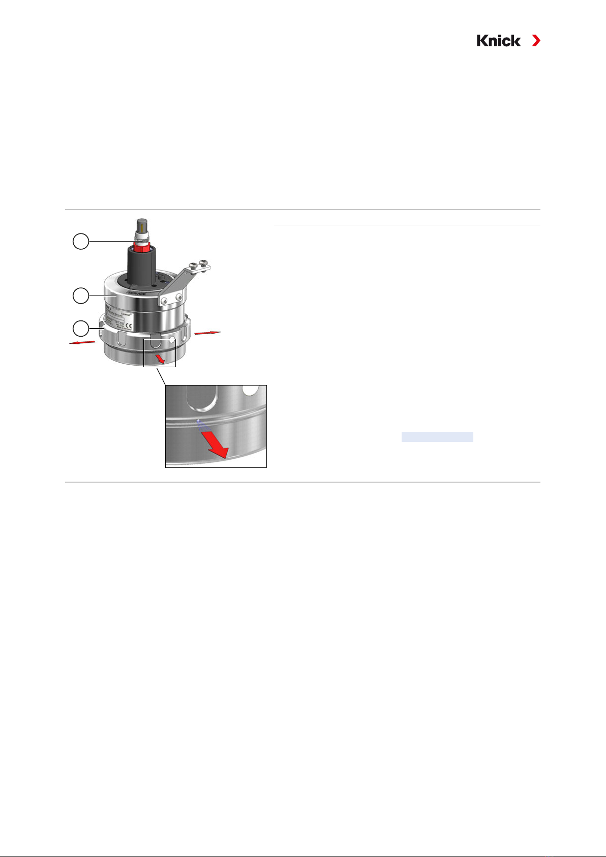
2.7 SERVICE/PROCESS Limit Positions ................................................................................................................. 18
3 Installation.................................................................................................................................... 19
3.1 General Installation Instructions..................................................................................................................... 19
3.2 Retractable Fitting: Installation ....................................................................................................................... 20
3.3 Media Connection / ZU0631: Installation on Strain Relief Bracket..................................................... 20
3.4 Outlet........................................................................................................................................................................ 21
3.4.1 Outlet Hose: Installation Instructions .............................................................................................. 21
3.4.2 Outlet Hose: Installation ....................................................................................................................... 22
3.5 Media Connection................................................................................................................................................ 23
3.5.1 Media Connection: Installation Instructions ................................................................................. 23
3.5.2 Multiplug: Installation ........................................................................................................................... 24
3.5.3 Electro-Pneumatic Controller: Connection.................................................................................... 24
3.5.4 ZU0631 Standard Media Connection: Installation...................................................................... 24
3.6 Sensor Cable: Installation .................................................................................................................................. 25
4 Commissioning............................................................................................................................. 26

Ceramat WA153
iv
5 Operation ...................................................................................................................................... 27
5.1 Moving into the Process Position (PROCESS Limit Position)................................................................. 27
5.2 Moving into the Service Position (SERVICE Limit Position)................................................................... 27
5.3 Installing and Removing a Sensor.................................................................................................................. 28
5.3.1 Safety Instructions when Installing and Removing Sensors ................................................... 28
5.3.2 Solid-Electrolyte Sensor: Installation ............................................................................................... 28
5.3.3 Solid-Electrolyte Sensor: Removal .................................................................................................... 29
5.3.4 Liquid-Electrolyte Sensor: Installation............................................................................................. 30
5.3.5 Liquid-Electrolyte Sensor: Removal.................................................................................................. 31
5.4 Cavity Rinsing ........................................................................................................................................................ 32
6 Maintenance ................................................................................................................................. 33
6.1 Inspection and Maintenance ........................................................................................................................... 33
6.1.1 Inspection and Maintenance Intervals............................................................................................ 33
6.1.2 Used and Approved Lubricants ......................................................................................................... 33
6.1.3 Knick Premium Service.......................................................................................................................... 34
6.1.4 Immersion Lock Without a Mounted Solid-Electrolyte Sensor: Functional Test .............. 34
6.2 Corrective Maintenance..................................................................................................................................... 34
6.2.1 Corrective Maintenance Safety Instructions ................................................................................. 34
6.2.2 Drive Unit: Disassembly ........................................................................................................................ 35
6.2.3 Drive Unit: Assembly.............................................................................................................................. 36
6.2.4 Knick Repair Service ............................................................................................................................... 37
7 Troubleshooting........................................................................................................................... 38
8 Removal from Operation ............................................................................................................. 40
8.1 Retractable Fitting: Removal............................................................................................................................ 40
8.2 Returns ..................................................................................................................................................................... 40
8.3 Disposal.................................................................................................................................................................... 40
9 Spare Parts, Accessories, and Tools............................................................................................. 41
9.1 Seal Kits .................................................................................................................................................................... 41
9.2 Spare Parts .............................................................................................................................................................. 44
9.3 Accessories.............................................................................................................................................................. 45
9.4 Tools .......................................................................................................................................................................... 46
10 Dimension Drawings.................................................................................................................... 47
11 Specifications................................................................................................................................ 51
Appendix....................................................................................................................................... 52
Glossary......................................................................................................................................... 55
Index.............................................................................................................................................. 56

Ceramat WA153
5
1 Safety
This document contains important instructions for the use of the product. Always follow all instructions
and operate the product with caution. If you have any questions, please contact Knick Elektronische
Messgeräte GmbH & Co. KG (sometimes hereafter referred to as "Knick") using the information provided
on the back page of this document.
1.1 Intended Use
The Ceramat WA153 is a retractable fitting for installation in boilers, tanks, and pipes. The product is
used to mount a sensor for measuring process parameters. The sensor is immersed in the process
medium by the Ceramat WA153. The Ceramat WA153 is pneumatically operated.
Cleaning, calibration, or sensor replacement under process conditions by the customer (hereinafter
sometimes referred to as the "operating company") may be conducted, subject to the requirements
set forth herein, by placing the product into the service position (SERVICE limit position).
If the product is used with any product or part not authorized by Knick, the operating company as-
sumes all risks and liabilities related thereto.
The Ceramat WA153 can be used with the following sensor types:
Solid-electrolyte sensors Outer diameter 12mm, length225 mm, sensor head thread PG13.5
Liquid-electrolyte sensors Outer diameter 12mm, length 250mm
Optical sensors1) Body diameter 12mm or 12.7mm (½″)
For further information, refer to the applicable documentation of the sensor manufacturer.
The defined operating conditions must be observed when using this product. ➜Specifications, p. 51
Thanks to its modular design, Ceramat WA153 can be adapted to changed conditions by the customer.
➜Changes for Different Conditions, p. 17
USE CAUTION AT ALL TIMES WHEN INSTALLING, USING, MAINTAINING OR OTHERWISE INTERACTING WITH
THE PRODUCT. ANY USE OF THE PRODUCT EXCEPT AS SET FORTH HEREIN IS PROHIBITED, AND MAY RESULT
IN SERIOUS INJURY OR DEATH, AS WELL AS DAMAGE TO PROPERTY. CUSTOMER SHALL BE SOLELY RESPON-
SIBLE FOR ANY DAMAGES RESULTING FROM OR ARISING OUT OF AN UNINTENDED USE OF THE PRODUCT.
The Ceramat WA153-X version is certified for operation in explosive atmospheres.
➜Operation in Explosive Atmospheres, p. 7
1.2 Personnel Requirements
Customer shall ensure that any personnel using or otherwise interacting with the product is adequately
trained and has been properly instructed.
The operating company shall comply and cause its personnel to comply with all applicable laws, regu-
lations, codes, ordinances and relevant industry qualification standards related to product. Failure to
comply with the foregoing shall constitute a violation of operating company’s obligations concerning
the product, including but not limited to an unintended use as described in this document.
1) Use with optical sensors requires additional adapters. The special datasheets contain information on the design
and use of the adapters. ➜Product Code, p. 10

Ceramat WA153
6
1.3 Safeguards
The Ceramat WA153 safety concept is based on the interplay of functions within a Knick process analy-
sis system. The Ceramat WA153 safeguards and safety functions require the functions of the electro-
pneumatic controller and the process analyzer. ➜Process Analysis System: Installation Example, p. 19
Safeguards and safety functions are not available if the Ceramat WA153 is operated without a Knick
process analysis system. The operating company must assess the risks and take appropriate action. It
must be possible to safely isolate media and power connections from the Ceramat WA153 using shut-
off devices.
Use the product as intended only. ➜Intended Use, p. 5
1
2
3
Immersion lock without a mounted solid-electrolyte sensor
The safeguard is only available for versions of the Ceramat
WA153 intended for solid-electrolyte sensors and when using a
Knick process analysis system.
➜Process Analysis System: Installation Example, p. 19
The safeguard is not available in versions of the Ceramat WA153
that have a sensor socket with a PEEK scraper or if a sensor
socket is retrofitted with a PEEK scraper. ➜Spare Parts, p. 44
The safeguard function is only available if the O‑ring and the
compression ring are correctly installed on the solid-electrolyte
sensor(1). ➜Installing and Removing a Sensor, p. 28
Function: Moving into the process position (PROCESS limit posi-
tion) without or with an incorrectly mounted solid-electrolyte
sensor(1) can be detected and prevented.
Compressed air noticeably and audibly escapes through holes un-
derneath the coupling nut(3) of the drive(2). This compressed air
is detected by a flow switch in the electro-pneumatic controller.
The process analyzer displays a Sensor Removed message; the
Ceramat WA153 does not move into the process position
(PROCESS limit position).
Environmental influences may affect the functionality of safeguards (e.g. components stuck together
by process medium). ➜Residual Risks, p. 6
See also
➜Immersion Lock Without a Mounted Solid-Electrolyte Sensor: Functional Test, p. 34
1.4 Residual Risks
The product has been developed and manufactured in accordance with generally accepted safety
rules and regulations, as well as an internal risk assessment. Despite the foregoing, the product may
among others bear the following risks:
Environmental Influences
The effects of moisture, ambient temperature, chemicals, and corrosion can negatively impact the safe
operation of the product. Please observe the following instructions:
• Only operate Ceramat WA153 in compliance with the stated operating conditions.
➜Specifications, p. 51
• Install the product inside a protected area of the plant. Alternatively, take appropriate action to
protect the Ceramat WA153.
• If using aggressive chemical process media, adjust the inspection and maintenance intervals
accordingly. ➜Inspection and Maintenance, p. 33

Ceramat WA153
7
• Adhering and sticky process media can impact the functionality of Ceramat WA153 (e.g.,by caus-
ing components to stick together). Adjust the inspection and maintenance intervals accordingly.
➜Inspection and Maintenance, p. 33
1.5 Hazardous Substances
IN THE EVENT OF ANY CONTACT WITH HAZARDOUS SUBSTANCES OR OTHER INJURY HEREUNDER, SEEK IM-
MEDIATE MEDICAL ATTENTION OR FOLLOW APPLICABLE PROCEDURES TO ADDRESS HEALTH AND SAFETY
OF PERSONNEL. FAILURE TO SEEK IMMEDIATE MEDICAL ATTENTION MAY RESULT IN SERIOUS INJURY OR
DEATH.
In certain situations (e.g., sensor replacement or corrective maintenance), personnel may come into
contact with the following hazardous substances:
• Process medium
• Calibration or cleaning medium
• Lubricant
The operating company is responsible for conducting a hazard assessment.
See the relevant manufacturers’ safety data sheets for hazard and safety instructions on handling haz-
ardous substances.
1.6 Operation in Explosive Atmospheres
The Ceramat WA153-X is certified for operation in explosive atmospheres.
• EU-Type Examination Certificate KEMA04ATEX4035X
Explosion protection is ensured under atmospheric conditions with an absolute pressure of
0.8…
1.1bar and an ambient temperature of -20…60°C. See the manufacturer’s specifications for in-
formation on the durability of the retractable fitting. ➜Specifications, p. 51
Exceeding the standardized atmospheric conditions within the manufacturer’s specifications, e.g., with
regard to the ambient temperature and pressure, does not endanger the retractable fitting’s durability.
Related certificates are included in the product’s scope of delivery and are available at www.knick.de
in the current version.
Observe all applicable local and national codes and standards for the installation of equipment in
explosive atmospheres. For further guidance, consult the following:
• IEC60079-14
• EU directives 2014/34/EU and 1999/92/EC(ATEX)
1.6.1 Possible Ignition Hazards During Installation and Maintenance
To avoid mechanically generated sparks, handle the Ceramat WA153-X with care and apply suitable
measures, e.g., use covers and pads.
The metallic parts of the Ceramat WA153-X must be connected to the plant’s equipotential bonding
using the metallic process connection or the grounding connection provided for that purpose.
When components are replaced with genuine Knick spare parts made of other materials (e.g. O-rings),
the information given on the nameplate may deviate from the actual version of the Ceramat WA153-X.
The operating company must assess and document this deviation.
➜Nameplates, p. 12
Mechanically generated sparks
Single impacts on metal parts or collisions between metal parts of the Ceramat WA153-X are not a
potential ignition source only if the following conditions are met:
• Possible impact velocity is less than 1m/s
• Possible impact energy is less than 500J

Ceramat WA153
8
If these conditions cannot be ensured, the operating company must reassess single impacts on metal
parts or collisions between metal parts as potential sources of ignition. The operating company must
implement suitable risk minimization measures, e.g., by ensuring a non-explosive atmosphere.
1.6.2 Possible Ignition Hazards During Operation
When using non-water-based cleaning, rinsing, or calibration media with a low conductivity of less
than 1nS/m, electrostatic charging of internal, conductive components may occur. The operating
company must assess the associated risks and implement appropriate measures.
The sensors that are used must be approved for operation in hazardous locations. Further information
can be found in the sensor manufacturer’s documentation.
1.7 Safety Training
Upon request, Knick Elektronische Messgeräte GmbH & Co. KG will provide safety instruction and
product training during initial commissioning of the product. Further information is available from the
relevant Knick representatives.
1.8 Maintenance and Spare Parts
Preventive Maintenance
Preventive maintenance can keep the product in good condition and minimize downtimes.
Knick provides recommended inspection and maintenance intervals. ➜Maintenance, p. 33
Lubricants
Only use lubricants approved by Knick. Special applications or upgrades to special lubricants are avail-
able on request. Usage of any other lubricants shall constitute an unintended use of the product.
➜Maintenance, p. 33
Tools and Mounting Aids
Special and accessory tools help maintenance personnel to replace components and wear parts safely
and professionally. ➜Tools, p. 46
Spare Parts
For professional corrective maintenance of the product, only use Knick genuine spare parts. Usage of
any other spare parts shall constitute an unintended use of the product.
➜Spare Parts, p. 44
Repair Service
The Knick Repair Service offers professional corrective maintenance on the Ceramat WA153 to the
original quality. Upon request, a replacement unit can be obtained for the period of the repair.
Further information can be found at www.knick.de.

Ceramat WA153
9
2 Product
2.1 Package Contents
• Ceramat WA153 in the version ordered
• User Manual
• As applicable, supplementary datasheet for special versions 1)
• EU Declaration of Conformity
• EU-Type-Examination Certificate 1)
2.2 Product Identification
The different versions of the Ceramat WA153 are coded in a product code.
The product code is stated on the nameplate, the delivery note, and the product packaging.
➜Nameplates, p. 12
2.2.1 Example of a Version
Basic device with pneum. drive, stainless steel WA153–N0KBB01105BD10–000
Explosion protection None N –
Sensor Sensor ⌀ 12mm with PG 13.5 0 –
Material of seals FFKM K –
Sensor protection tube material Hastelloy C22 B –
Sensor socket material Hastelloy C22, without protection B 0 –
Scraper for sensor socket PEEK, natural 1 –
Immersion depth Immersion depth 105mm (max.) 1 0 5 –
Process-wetted material Hastelloy C22 B –
Process connection Flange, loose, ANSI 316, 150lbs, 2″D 1 –
Probe guard None 0 –
Special version None – 0 0 0
1) Supplied depending on the ordered version of the Ceramat WA153 ➜Product Code, p. 10

Ceramat WA153
10
2.2.2 Product Code
Basic device with pneum. drive, stainless steel version WA153 – _ _ _ _ _ _ _ _ _ _ _ _ _ _ – _ _ _
Explosion protection ATEX Zone0 X –
None N –
Sensor Sensor ⌀ 12mm with PG13.5 0 –
pH sensor ⌀ 12mm with pressurization unit,
pressure chamber for compressed air supply 1 –
Optical sensor ⌀½″ (12.7mm) 2 –
Optical sensor ⌀ 12mm 3 –
Gasket material FKM A –
EPDM B –
EPDM – FDA E –
FKM – FDA F –
FFKM – FDA H –
FFKM K –
Sensor protection
tube material
Hastelloy C221) B –
PEEK E –
1.4404 H –
Titanium1) T –
Sensor socket
material
Hastelloy C22, without protection B 0 –
Hastelloy C22, short protection B 1 –
1.4404, without protection H 0 –
1.4404, short protection H 1 –
1.4404, long protection H 2 –
1.4404, full protection H 3 –
PEEK, without protection E 0 –
Titanium, without protection T 0 –
Titanium, short protection T 1 –
Scraper for sensor
socket
None 0 –
PEEK, natural 1 –
Immersion depth Special immersion depth 23 - 104 mm (1mm increments) 0 0 0 –
Immersion depth 105mm (max.) 1 0 5 –
Process-wetted
material
Hastelloy C221) B –
1.4404 H –
Titanium1) T –
Process connection Flange, loose, 1.4571, PN10/16, DN50 B 1 –
Flange, loose, 1.4571, PN10/16, DN65 B 2 –
Flange, loose, 1.4571, PN10/16, DN80 B 3 –
Flange, loose, 1.4571, PN10/16, DN100 B 4 –
Flange, loose, 1.4571, PN10/16, DN1251) B 5 –
Flange, loose, 1.4571, PN10/16, DN1501) B 6 –
Flange, loose, 1.4571, PN10/16, DN2001) B 7 –
Flange, loose, 1.4571, PN40, DN50 E 1 –
Flange, loose, 1.4571, PN40, DN65 E 2 –
Flange, loose, 1.4571, PN40, DN80 E 3 –
1) Special option, lead time on request

Ceramat WA153
11
Basic device with pneum. drive, stainless steel version WA153 – _ _ _ _ _ _ _ _ _ _ _ _ _ _ – _ _ _
Flange, loose, 1.4571, PN40, DN100 E 4 –
Flange, loose, 1.4571, PN40, DN1251) E 5 –
Flange, loose, 1.4571, PN40, DN1501) E 6 –
Flange, loose, 1.4571, PN40, DN2001) E 7 –
Dairy pipe DN50 C 1 –
Dairy pipe DN65 C 2 –
Dairy pipe DN80 C 3 –
Dairy pipe DN100 C 4 –
Flange, loose, ANSI 316, 150lbs, 2″D 1 –
Flange, loose, ANSI 316, 150 lbs, 2½″D 2 –
Flange, loose, ANSI 316, 150lbs, 3″D 3 –
Flange, loose, ANSI 316, 150lbs, 3.5″1) D 4 –
Flange, loose, ANSI 316, 150lbs, 4″1) D 5 –
Flange, loose, ANSI 316, 150lbs, 5″1) D 6 –
Flange, loose, ANSI 316, 150lbs, 6″1) D 7 –
Flange, loose, ANSI 316, 300lbs, 2″P 1 –
Flange, loose, ANSI 316, 300 lbs, 2½″P 2 –
Flange, loose, ANSI 316, 300lbs, 3″P 3 –
Flange, loose, ANSI 316, 300lbs, 3.5″1) P 4 –
Flange, loose, ANSI 316, 300lbs, 4″1) P 5 –
Flange, loose, ANSI 316, 300lbs, 5″1) P 6 –
Flange, loose, ANSI 316, 300lbs, 6″1) P 7 –
G2¼ for ARF210/215 K 8 –
Clamp 2.5″J 3 –
Clamp DN 50, DIN 32676 J H –
BioControl, 1.4404, DN 651) L 2 –
Varivent 1.4404 (≥ DN 50) V 1 –
Probe guard None 0 –
With, version 1 1 –
Special version None – 0 0 0
Equipped with special grease (provided by customer) – 0 0 1
Sensor protection tube for optical sensor (Hellma) with ⌀12mm
and additional anti-twist protection for the sensor cables, rotating
adapter 12mm/PG13.5 (according to drawing)
– 0 0 B
Customer-specific special datasheet – 0 0 F
Sensor protection tube for optical sensor with ⌀12mm or ½″(12.7mm)
and additional anti-twist protection for the sensor cables, rotating adapter
⌀12mm (½″)/PG13.5 (according to drawing)
– 0 0 J
Ceramat, inlet and outlet made of 1.4404 – 0 0 K
1) Special option, lead time on request

Ceramat WA153
12
2.3 Nameplates
The Ceramat WA153 is identified by nameplates on the drive unit and the process unit. The informa-
tion provided on the nameplates varies according to the version of the Ceramat WA153.
Nameplate, Version Without ATEX Approval
Note: The figure shows a nameplate for the Ceramat WA153-N version by way of example.
WA153-N0KBB31*******-00M
2235208 / 1941
WA153-N*K****105BD10-00M
2235210 / 1932
3
4
10
9
8
7
6
5
11
1
2
3
4
8
7
6
5
9
11
1Drive unit nameplate 7Product line / assembly group
2Process unit nameplates 8Manufacturer
3Manufacturer’s address with designation of origin 9Product line
4Max. operating pressure and temperature range 1) 10 IP protection
5Serial number / year and week of production 11 CE mark
6Type (product code)
1) Further information is available in the related EU Type Examination Certificate and in the ➜Safety, p. 5 and
➜Specifications, p. 51 chapters.

Ceramat WA153
13
Nameplate, Version With ATEX Approval
Note: The figure shows a nameplate for the Ceramat WA153-X version by way of example.
WA153-X*K****035HB10-000
2235211 / 1932
WA153-X0KHH00*******-000
2235209 / 1941
1
2
3
4
5
6
7
8
9
10
11
12 13
14
15
13
15
12
11
10
9
7
16
8
1Drive unit nameplate 9Serial number/year and week of production
2Process unit nameplate 10 Type (product code)
3No self heating / special conditions 1) 11 Product line / assembly group
4Permissible ambient temperature 12 Manufacturer
5ATEX marking / information on explosion protection 13 Product line
6EU Type Examination Certificate test number 14 IP protection
7Manufacturer’s address with designation of origin 15 CE marking with identification number
8Max. operating pressure and temperature range 1) 16 Reference to ATEX information for the drive unit
1) Further information is available in the related EU Type Examination Certificate and in the ➜Safety, p. 5 and
➜Specifications, p. 51 chapters.

Ceramat WA153
14
2.4 Symbols and Markings
Special conditions and danger points! Observe the safety information and instructions on safe use of the
product as outlined in the product documentation.
Reminder to read the documentation.
CE marking with identification number of the notified body involved in the production control.
ATEX marking1) of the European Union for operation of Ceramat WA153-X in explosive atmospheres.
➜Operation in Explosive Atmospheres, p. 7
IP66 protection: The product is dust-tight and offers complete protection against contact as well as
protection against strong water jets.
Display indicating process position (PROCESS limit position).
➜Moving into the Process Position (PROCESS Limit Position), p. 27
Display indicating service position (SERVICE limit position).
➜Moving into the Service Position (SERVICE Limit Position), p. 27
2.5 Design and Function
Ceramat WA153 consists of two main assemblies:
• Drive unit
• Process unit
The drive unit is connected to the process unit with a coupling nut. The drive unit and process unit can
be separated under process conditions. ➜Drive Unit: Disassembly, p. 35
Different versions of drive and process unit can be combined.
➜Changes for Different Conditions, p. 17
The process connection is used to fasten the Ceramat WA153 to the process port on the measuring
point.
The pneumatically operated drive unit moves the Ceramat WA153 into the service position (SERVICE
limit position) or the process position (PROCESS limit position).
➜SERVICE/PROCESS Limit Positions , p. 18
1) Availability is dependent on the ordered version. ➜Product Code, p. 10

Ceramat WA153
15
2.5.1 Retractable Fitting
Note: The figure shows an example version of the Ceramat. ➜Product Code, p. 10
1
2
3
4
5
6
7
8
9
10
11
12
13
1Drive unit 8Multiplug1)
2Process unit 9Outlet hose1)
3Sensor housing with ceramic rotary slides 10 Media connection1)
4Process connection (e.g., flange) 11 Sensor cable1)
5Coupling nut 12 Strain relief bracket
6Drive unit 13 Sensor holder
7Media outlet
1) Not included in the Ceramat WA153 package contents

Ceramat WA153
16
2.5.2 Drive Units
Note: The figure shows a selection from the product line. ➜Product Code, p. 10
1 2
1Drive unit, solid-electrolyte sensor 2Drive unit, liquid-electrolyte sensor
2.5.3 Process Connections
Note: The figure shows a selection from the product line. ➜Product Code, p. 10
12
3
1Flange 3Varivent
2Dairy pipe

Ceramat WA153
17
2.6 Changes for Different Conditions
Ceramat WA153 can be adapted to changed conditions by the customer. Prior to making any changes,
contact Knick Elektronische Messgeräte GmbH & Co. KG. The following are examples of possible
changes:
• Change to a different process connection ➜Process Connections, p. 16
• Replacement of process-wetted components with other material characteristics
➜Maintenance, p. 33
• Replacement of the drive unit to mount a different sensor type ➜Drive Units, p. 16
Any changes may result in deviations between the information on the nameplate and the actual
version of the Ceramat WA153. The operating company must assess and document the changes.
In the event of a change to the version, the product must be identified accordingly.
It is recommended that changes to the Ceramat WA153 are carried out by the Knick Repair Service.
After making the necessary changes, a functional and pressure test is carried out and, if necessary,
a modified nameplate is attached. ➜Knick Repair Service, p. 37
More information on changes can be found in the related supplementary datasheet.

Ceramat WA153
18
2.7 SERVICE/PROCESS Limit Positions
Ceramat WA153 can assume two limit positions (service or process position).
Note: The Ceramat WA153 is only disconnected from the process in the service position (position indi-
cator points to SERVICE). This is not the case in any other position, i.e., there remains contact with the
process.
Service position (SERVICE limit position)
• The ceramic rotary slide is closed (sensor is retracted in the sensor housing).
• The sensor is not in contact with the process medium.
• The position indicator points to SERVICE.
• The sensor can be installed, removed, and, as necessary, cleaned under process conditions.
• The drive unit can be removed under process conditions.
Process position (PROCESS limit position)
• The ceramic rotary slide is open (sensor is extended out of the sensor housing).
• The sensor is in contact with the process medium.
• The position indicator points to PROCESS.
• The desired process parameters can be measured.
Service position (SERVICE limit position) Process position (PROCESS limit position)
On reaching one of the limit positions, a contact is closed in the limit switch. The electrical signal can
be processed further, for example in the electro-pneumatic controller, the process analyzer, or the
process control system(PCS).
See also
➜Moving into the Service Position (SERVICE Limit Position), p. 27
➜Moving into the Process Position (PROCESS Limit Position), p. 27

Ceramat WA153
19
3 Installation
3.1 General Installation Instructions
Process Analysis System: Installation Example
The Ceramat WA153 is designed for operation within a fully automatic Knick process analysis system.
The process analysis system may typically comprise the following products:
• Protos 3400(X) process analyzer
• Unical 9000(X) electro-pneumatic controller
• Ceramat WA153 retractable fitting
Note: The figure shows an example installation of a Knick process analysis system. Further information
can be found at www.knick.de.
1
2
3
4
5
6
1Unical9000(X) electro-pneumatic controller 4Media connection with multiplug
2Service switch 5Media adapter with metering pump
3Ceramat WA153 retractable fitting 6Protos3400(X) process analyzer
Note: The Ceramat WA153 may also be operated without a process analysis system. In this case, acces-
sory ZU0631, “Standard media connection”, is required. The Ceramat WA153 is then controlled via the
process control system(PCS) or manually with accessory ZU0646, “Pneumatically operated manual
control valve”. ➜Accessories, p. 45

Ceramat WA153
20
3.2 Retractable Fitting: Installation
WARNING! Risk of explosion from mechanically generated sparks when used in explosive
atmospheres. Take appropriate action to prevent mechanically generated sparks. Follow the safety
instructions. ➜Operation in Explosive Atmospheres, p. 7
A
01. Check scope of delivery of the Ceramat WA153 for completeness. ➜Package Contents, p. 9
02. Check the Ceramat WA153 for damage.
03. Ensure sufficient installation clearance to mount the sensor and allow the hoses and cables to
move freely. ➜Dimension Drawings, p. 47
Note: The installation angle of the Ceramat WA153 depends on the sensor type. An installation angle
of up to 10° above the horizontal plane is permissible for all sensor types. An installation angle of 360°
(i.e., upside down, see view A) is only permitted if using sensors approved for upside-down operation.
04. Fasten the Ceramat WA153 to the process port using the process connection.
05. Optional: If using the product in explosive atmospheres, connect the metallic parts of the Ceramat
WA153 to the plant’s equipotential bonding system.
See also
➜Operation in Explosive Atmospheres, p. 7
➜Commissioning, p. 26
3.3 Media Connection / ZU0631: Installation on Strain Relief Bracket
Note: The figure shows installation on the Ceramat WA153 strain relief bracket when using the media
connection. The steps involved are the same when using accessory ZU0631, “Standard media connec-
tion”. ➜Process Analysis System: Installation Example, p. 19
1
2
3
4
01. Position the bracket(2) of the media connection (1) on the strain relief bracket (4) of the Ceramat
WA153. If necessary, loosen the screws (3) a few rotations.
02. Tighten the screws (3) using a screwdriver.
Other manuals for Ceramat WA 153
1
Table of contents
Popular Bathroom Fixture manuals by other brands

Kohler
Kohler Mira Sport Max J03G Installation and user guide

Moen
Moen 186117 Series installation guide

Hans Grohe
Hans Grohe Raindance Showerpipe 27235000 Instructions for use/assembly instructions

Signature Hardware
Signature Hardware ROUND SWIVEL BODY SPRAY 948942 Install

fine fixtures
fine fixtures AC3TH installation manual

LIXIL
LIXIL HP50 Series quick start guide