KNOVA KN 8052 User manual

KNOVA
Digital multimeter
Multímetro digital
600V
KN 8052

TABLE OF CONTENTS
Safety information 1
Safety symbols 1
Maintenance 1
During use 2
General description 2
Front panel 3-4
Specications 4
General 4-7
Operating instructions 8-10
Battery & fuse replacement 11
Accessories 11

KNOVA
This multimeter has been designed according to IEC61010-1 concerning
electronic measuring instruments with an overvoltage category (CATII)
and pollution 2. Follow all safety and operation instructions to ensure that
the meter is used safely and is kept in good operating condition.
Full compliance with safety standards can be guaranteed only with test
leads supplied. If necessary, they must be replaced with the type specied
in this manual.
1
SAFETYSYMBOLS
Important safety information, refer to the operating
manual.
Dangerous voltage may be present.
Anti-garbage
Double insulation (Protection class II).
Fuse must be replaced with rating specied in the
manual.
1. SAFETY INFORMATION
MAINTENANCE
• Before opening the case, always disconnect test leads from all
energized circuits.
• For continue protection against re; replace fuse only
with the specied voltage and current ratings:
250mA/250V(Quick Acting) 10A/250V(Quick Acting)
• Never use the meter unless the back cover is in place
and fastened completely.
Do not use abrasives or solvents on the meter. To clean
It, use a damp cloth and mild detergent only.

2
DURINGUSE
• Never exceed the protection limit values indicated in the specications
for each range of measurement.
• When the meter is linked to measurement circuit, do not touch the
unused terminals.
• Never use the meter to measure voltages that might exceed 600V
above earth ground in category II installations.
• When the value scale to be measured is unknown beforehand, set the
range selector at the highest position.
• Before rotating the range selector to change functions, disconnect test
leads from the circuit under test.
• When carrying out measurements on TV or switching power circuits
always remember that there may be high amplitude voltages pulses
at test points, which can damage the meter.
• Always be careful when working with voltages above 60Vdc or 30V ac
rms. Keep ngers behind the probe barriers when making voltage
measurements with test leads.
• Never perform resistance measurements on live circuits.
GENERALDESCRIPTION
The meter is a handheld 31/2 digital multimeter for measuring
DC and AC voltage, DC current, Resistance, Diode, and
Continuity Test, battery operated.
The meter has a back light function to be used in a dark
environment.

KNOVA
3
1
2
3
4
5
6
8
7
FRONT PANEL

4
+
-
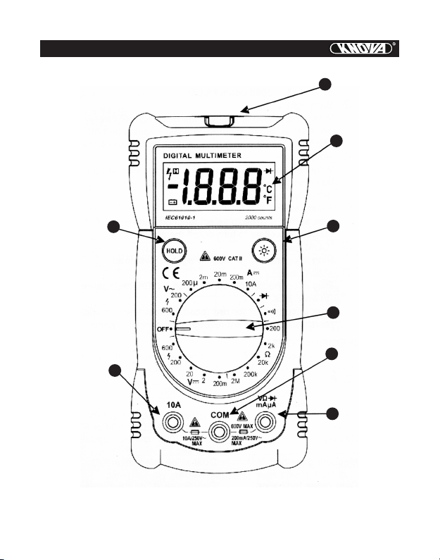
FRONTPANELDESCRIPTION
1- Non-contact voltage detection indicator (red LED)
2- Display: 3 1/2 digit,(2000 count) LCD.
3- Back light: When this button is pushed, the Back light of display is
turned on. After about 10 seconds, the Back light will be turned off
automatically. In order to turn on the Back light again, just push this
button once.
4- Hold button: When this button is pushed, the display will keep the
last reading and an “ ” symbol will appear on the LCD until you push
it again.
5- Rotary switch: This switch is used to select functions and desired
ranges as well as to turn on/off the meter.
6- “COM” jack : Plug in connector for black (negative) test lead.
7- “10A” jack: Plug in connector for red test lead for10A measurement.
8- “VΩmA” jack: Plug in connector for red (positive) test lead for voltage,
resistance and current (except 10A) measurements.
SPECIFICATIONS
Accuracy is specied for a period of one year after calibration and at 18
to 28℃ (64°F to 82°F) with relative humidity to 80%.
GENERAL
Maximum voltage between terminals and earth ground: CATII 600V
Fuse protection: F 250mA/250V 10A/250V
Power: 9V battery, NEDA 1604 or 6F22
Display: LCD 2000 counts, updates 2-3/ sec.
Measuring method: Dual-slope integration A/D converter
Over range Indication: Only gure “1” on the display
Polarity indication: “-”displayed for negative polarity
Operating Environment: 0 to 40℃
Storage temperature: -10℃ to 50℃.
Low battery indication: “ ”appears on the display
Size: 140mm×67mm×30mm
Weight: Approx.112g.
H

KNOVA
5
Range Resolution Accuracy
200mV 100μV ±0.5% of rdg ± 2 digits
2V 1mV ±0.5% of rdg ± 2 digits
20V 10mV ±0.5% of rdg ± 2 digits
200V 100mV ±0.5% of rdg ± 2 digits
600V 1V ±0.8% of rdg ± 2 digits
Range Resolution Accuracy
200μA 0.1μA ±1% of rdg ± 2 digits
2mA 1μA ±1% of rdg ± 2 digits
20mA 10μA ±1% of rdg ± 2 digits
200mA 100μA ±1.5% of rdg ± 2 digits
10A 10mA ±3% of rdg ± 2 digits
Overload Protection: 250V rms. For 200mV range and 600V dc or rms.
ac for other ranges.
Overload Protection: F 250mA/250V fuse. F 10A/250V fuse
DCVOLTAGE
DCCURRENT

6
Range Resolution Accuracy
200V 100mV ±1.2% of rdg ± 10 digits
600V 1V ±1.2% of rdg ± 10 digits
Range Accuracy
If continuity exists (about less than 100Ω), built-in
buzzer will sound.
Show the approx. forward voltage drop of the diode.
Overload Protection: 600V dc or rms. ac for all ranges.
Frequency range: 40Hz to 400Hz
Response: Average responding, calibrated in rms. of a
sine wave.
Overload Protection: 250V dc or rms. ac.
ACVOLTAGE
DIODE&CONTINUITY

KNOVA
7
Range Resolution Accuracy
200Ω 0.1Ω ±0.8% of rdg ± 3 digits
2kΩ 1Ω ±0.8% of rdg ± 2 digits
20kΩ 10Ω ±0.8% of rdg ± 2 digits
200kΩ 100Ω ±0.8% of rdg ± 2 digits
2MΩ 1kΩ ±1.0% of rdg ± 2 digits
Maximum Open Circuit Voltage: 3.2 V
Overload Protection: 250V dc or rms. ac for all ranges.
RESISTANCE
Resolution Alerts
>AC90V Red LED lit
Non-contactvoltagedetection

8
OPERATINGINSTRUCTIONS
DCVOLTAGEMEASUREMENT
1. Connect the red test lead to the “V.Ω.mA” jack and the
black lead to the “COM” jack.
2. Set rotary switch at desired DCV position. If the voltage
to be measured is not known beforehand, set range
switch at the highest range position and then reduce it
until satisfactory resolution is obtained.
3. Connect test leads across the source or load being
measured.
4. Read voltage value on the LCD display along with the
polarity of the red lead connection.
DCCURRENTMEASUREMENT
1. Connect the red test lead to the “V.Ω.mA” jack and the
black test lead to “COM” jack. (For measurements
between 250mA and 10A, remove red lead to“10A”jack.)
2. Set the rotary switch at desired DCA position.
3. Open the circuit in which the current is to be measured, and connect
test leads in series with the circuit.
4. Read current value on LCD display along with the
polarity of red lead connection.
ACVOLTAGEMEASUREMENT
1. Connect the red test lead to “V.Ω. mA” jack and the
black test lead to the “COM” jack.
2. Set the rotary switch at desired ACV position.
3. Connect test leads across the source or load being
measured.
4. Read voltage value on the LCD display.

KNOVA
9
RESISTANCEMEASUREMENT
1. Connect the red test lead to “V. Ω. mA” jack and black
test lead to the “COM” jack. (The polarity of red lead is
positive “+”.)
2. Set the rotary switch at desired ”Ω” range position.
3. Connect test leads across the resistor to be measured
and read LCD display.
4. If the resistance being measured is connected to a
circuit, turn off power and discharge all capacitors
before applying test probes.
DIODETEST
1. Connect the red test lead to “V.Ω.mA” jack and the
black test lead to the “COM” jack (The polarity of red
lead is positive “+”.).
2. Set the rotary switch at “ ” position.
3. Connect the red test lead to the anode of the diode to be tested and
the black test lead to the cathode of the diode.
The approx. forward voltage drop of the diode will be displayed. If the
connection is reversed, only gure “1” will be shown.
AUDIBLECONTINUITYTEST
1. Connect red test lead to “V.Ω.mA”, black test lead to “COM”.
2. Set range switch to “ ” position.
3. Connect test leads to two points of circuit to be tested.
If continuity exists, built-in buzzer will sound.

10
Non-contactvoltagedetection
1. When the meter head is close to the AC voltage eld, the LED light
the close distance is about 30mm from the AC voltage eld.
!WARNING
Even without LED indication, the voltage may still exist. Do
not rely on non-contact voltage detector to determine the presence
of voltage wire, Detection operation may be subject to socket design,
insulation thickness and different type and other factors

KNOVA
11
ACCESSORIES
• Operator’s instruction manual
• Set of test leads
• Gift box
• 9 volt battery. NEDA 1604 6F22 006P type (optional)
BATTERY&FUSEREPLACEMENT
If “ ”appears on display, it indicates that the battery
should be replaced.
The fuse rarely needs replacement and blows almost always as a result
of operator’s error.
To replace the battery and the fuse (250mA/250V and 10A/250V)
remove the 2 screws in the bottom of the case. Simply remove the old
one, and replace with a new one.
Be careful to observe battery polarity.
!WARNING
Before attempting to open the case, always be sure that test
leads have been disconnected from measurement circuits. Close case
and tighten screws completely before using the meter to avoid electrical
shock hazards.
+
-

TABLA DE CONTENIDOS
Información de seguridad 13
Símbolos de seguridad 13
Mantenimiento 13
Durante el uso 14
Descripción general 14
Panel frontal 15-16
Especicaciones 16
General 16-19
Instrucciones de operación 20-22
Cambio de bateria y fusibles 23
Accesorios 23

KNOVA
Este multímetro ha sido diseñado de acuerdo a la IEC61010-1
concerniente a los instrumentos electrónicos de medición con una
categoría de sobretensión (CATII) y contaminación de grado 2. Siga todas
las instrucciones de operación y seguridad para garantizar el uso seguro
del multímetro y su mantenimiento en buenas condiciones operativas.
El cumplimiento total de los estándares de seguridad sólo puede
garantizarse si se utilizan los cables de prueba provistos. De ser necesario,
deben reemplazarse por unos del mismo tipo, especicado en este manual.
13
SÍMBOLOSDESEGURIDAD
Información de seguridad importante, remítase al manual de
operación.
Posible presencia de voltaje peligroso.
Anti-basura
Doble aislamiento (Protección de clase II).
El fusible debe ser cambiado por uno de la categoría especicada
en el manual.
INFORMACIÓN DE SEGURIDAD
MANTENIMIENTO
• Antes de abrir la carcasa, desconecte siempre los cables de prueba de
todos los circuitos con electricidad.
• Para una protección contra el fuego asegurada, reemplace el fusible
únicamente por uno con el voltaje y las categorías de corriente
especicados; 250mA/250V (Acción Rápida)10A/250V(Acción Rápida)
• Nunca utilice el multímetro a menos que la cubiertatrasera esté
ubicada y ajustada completamente.
• No utilice abrasivos ni solventes sobre el multímetro. Para limpiarlo,
utilice un paño húmedo y detergente suave únicamente.

14
DURANTEELUSO
• Nunca sobrepase los valores del límite de protección indicados en las
especicaciones para cada escala de medición.
• Cuando el multímetro esté conectado a un circuito de medición, no
toque las terminales que no están en uso.
• Nunca utilice el multímetro para medir voltajes que puedan exceder los
600V sobre el nivel del suelo en instalaciones de categoría II
• Cuando la escala de valores a medir no se conoce de antemano, sitúe
el selector de escalas en la posición más alta.
• Antes de girar el selector de escalas para cambiar de función, desco
necte los cables de prueba del circuito a prueba.
• Al realizar mediciones de televisores o al cambiar los circuitos eléc
tricos, siempre recuerde que puede haber pulsos de voltajes de gran
amplitud en los puntos de prueba, que pueden dañar al multímetro.
• Siempre sea cuidadoso al trabajar con voltajes superiores a los 60V cd
ó 30V ac rms. Mantenga sus dedos detrás de las barreras de detección
cuando realice mediciones de voltaje con cables de prueba.
• Nunca realice mediciones de resistencia sobre circuitos vivos.
DESCRIPCIÓNGENERAL
El medidor es un multímetro digital portátil 31/2 para realizar medicio-
nes de voltaje CD y CA, Corriente CD, Resistencia, Diodo y Prueba de
Continuidad, con funcionamiento a batería. El multímetro cuenta con la
función de luz de fondo, que se utiliza en ambientes oscuros.

KNOVA
15
PANEL FRONTAL
1
2
3
4
5
6
8
7

+
-
DESCRIPCIÓNDELPANELFRONTAL
1- Indicador de detección de voltaje sin contacto (LED rojo)
2- Pantalla de 3 1/2 dígitos, (cuenta hasta 2000) LCD.
3- Luz de fondo: Cuando se pulsa este botón, se enciende la Luz de
fondo de la pantalla. Luego de aproximadamente 10 segundos, la Luz de
fondo se apaga automáticamente.
4- Botón “Retener”: Cuando se pulsa este botón, la pantalla retendrá
la última lectura y se visualizará el símbolo “ “en el LCD hasta que el
mismo se vuelva a pulsar.
5- Interruptor rotativo: Este interruptor se utiliza para seleccionar las fun-
ciones y escalas deseadas así como para encender/apagar el multímetro.
6- Conector “COM”: Conector de entrada para el cable de prueba negro
(negativo).
7- Conector de “10A”: Conector de entrada para el cable de prueba rojo
para mediciones de 10A.
8- Conector “VΩmA”: Conector de entrada para el cable de prueba rojo
(positivo) para mediciones de voltaje, resistencia y corriente
(exceptuando 10A).
ESPECIFICACIONES
La precisión se especica por el período de un año luego de la calibración
y a una temperatura de 18°C a 28°C (64°F a 82°F) con una humedad
relativa de hasta el 80%.
GENERAL
Máximo voltaje entre terminales y tierra: CATII 600V
Protección con Fusible: F 250mA/250V 10A/250V
Energía: 9V battery, NEDA 1604 or 6F22
Pantalla: LCD 2000 counts, updates 2-3/ sec.
Método de Medición: Dual-slope integration A/D converter
Indicación de Sobrepaso de escala: Only gure “1” on the display
Indicación de polaridad: “-”displayed for negative polarity
Temperatura Ambiente de Operación: 0 to 40℃
Temperatura de almacenamiento: -10℃ to 50℃.
Aviso de batería baja: “ ”appears on the display
Tamaño: 140mm×67mm×30mm
Peso: Approx.112g.
H
16

KNOVA
Escala Resolución Precisión
200mV 100μV ±0.5% de lectura ± 2 digitos
2V 1mV ±0.5% de lectura ± 2 digitos
20V 10mV ±0.5% de lectura ± 2 digitos
200V 100mV ±0.5% de lectura ± 2 digitos
600V 1V ±0.8% de lectura ± 2 digitos
Escala Resolución Precisión
200μA 0.1μA ±1% de lectura ± 2 digitos
2mA 1μA ±1% de lectura ± 2 digitos
20mA 10μA ±1% de lectura ± 2 digitos
200mA 100μA ±1.5% de lectura ± 2 digitos
10A 10mA ±3% de lectura ± 2 digitos
Protección de Sobrecarga: 250V rms. Para una escala de 200mV y
600V cd ó ca rms para otras escalas.
Protección de Sobrecarga: Fusible F 250mA/250V. Fusible F
10A/250V
VOLTAJECD
CORRIENTECD
17

Escala Resolución Precisión
200V 100mV ±1.2% de lectura ± 10 digitos
600V 1V ±1.2% de lectura ± 10 digitos
Escala Descripción
Si hay continuidad (por ejemplo, una resistencia menor a
100Ω), sonará la alarma incorporada.
Muestra la caída del voltaje directo aproximado del diodo.
Protección de Sobrecarga: 600V cd ó ac rms para todas las escalas.
Escala de frecuencia: 40Hz a 400Hz.
Respuesta: Respuesta promedio, calibrada en rms de onda sinusoidal.
Protección de Sobrecarga: 250V cd ó rms ac.
VOLTAJECA
DIODOS&CONTINUIDAD
18
Table of contents
Languages:
Other KNOVA Multimeter manuals