Amprobe 37XR-A User manual

37XR-A
Professional Digital Multimeter
Users Manual
99 Washington Street
Melrose, MA 02176
Fax 781-665-0780
TestEquipmentDepot.com

Manual Supplement 37XR-A Users
2 10/06
MADE IN TAIWAN
PATENTS PENDING
www.amprobe.com
5
6
3
4
10A MAX
FUSED
V
Hz
dBm
%
COM
10A
mA
H
400mA
MAX
FUSED
CAT 1000V
CAT 600V
TRUE RMS
MAX
1000V
750V
10A
V
V
Hz
mH
H
MIN MAX AVG RANGE HOLD
TTL CMOS
PEAK
REL
cal>2sec
OFF
A
mA
10A
LOGIC
%
dBm
AC+DC
RELREC CMOS
P-P+TTL
RANGE
m
VA
Hz
Mk
n F
CF
%
m
HdBm
MAXMINAVG HOLD
025 50 75 100
SLEEP OFF
1
2
37XR-A
37XR-A

MADE IN TAIWAN
PATENTS PENDING
www.amprobe.com
5
6
3
4
10A MAX
FUSED
V
Hz
dBm
%
COM
10A
mA
H
400mA
MAX
FUSED
CAT 1000V
CAT 600V
TRUE RMS
MAX
1000V
750V
10A
V
V
Hz mH
H
MIN MAX AVG RANGE HOLD
TTL CMOS
PEAK
REL
cal>2sec
OFF
A
mA
10A
LOGIC
%
dBm
AC+DC
RELREC CMOS
P-P+TTL
RANGE
m
VA
Hz
Mk
n F
CF
%
m
HdBm
MAXMINAVG HOLD
025 50 75 100
SLEEP OFF
1
2
37XR-A
37XR-A

1
37XR-A Digital Multimeter
Contents
Safety Information ..............................................................................................2
Symbols Used in this Manual ..........................................................................2
Introduction........................................................................................................3
Making Measurements........................................................................................3
Verify Instrument Operation.............................................................................3
Range Selection...............................................................................................3
Correcting an Overload (-or -) Indication..................................................3
Measuring DC Voltage ..................................... See Figure -1- ........................4
Measuring AC Voltage (True rms)..........See Figure -2 - & -3- ........................4
Preparing for Current Measurements...............................................................4
Measuring DC Current ..................................... See Figure -4- ........................4
Measuring AC Current (True rms)...........See Figure -3- & -5- ........................4
Measuring Resistance ..................................... See Figure -6- ........................5
Testing for Continuity ...................................... See Figure -7- ........................5
Testing Diodes................................................. See Figure -8- ........................5
Measuring Capacitance ................................... See Figure -9- ........................5
Measuring Inductance ................................... See Figure -10- ........................6
Measuring Frequency .................................... See Figure -11- ........................6
Measuring Dutycycle .................................... See Figure -12- ........................6
Measuring dBm ............................................ See Figure -13- ........................6
Testing Logic Levels ..................................... See Figure -14- ........................6
Additional Features .............................................................................................7
Input Test Lead Warning..................................................................................7
True-rms Measurements .................................................................................7
MIN MAX AVG Measurements.........................................................................7
Peak Hold Measurements ................................................................................7
Beeper Off........................................................................................................8
Auto Power Off ................................................................................................8
REL (Relative) Measurements..........................................................................8
HOLD Measurements.......................................................................................8
Backlight..........................................................................................................8
Product Maintenance..........................................................................................9
Battery and Fuse Replacement....................... See Figure -15- ........................9
Repair .................................................................................................................9
WARRANTY...................................................................................................10
Specifications ...................................................................................................11
Users Manual

2
Safety Information
xThe 37XR-A Digital Multimeter is UL, CSA, and EN61010-1 certified for
Installation Category III – 600V and Category II – 1000V. It is recommended for
use with local level power distribution, appliances, portable equipment, etc,
where only smaller transient overvoltages may occur, and not for primary
supply lines, overhead lines and cable systems.
xDo not exceed the maximum overload limits per function (see specifications)
nor the limits marked on the instrument itself. Never apply more than 1000V
dc/750 V ac rms between the test lead and earth ground.
xInspect the DMM, test leads and accessories before every use. Do not use any
damaged part.
xNever ground yourself when taking measurements. Do not touch exposed
circuit elements or test probe tips.
xDo not operate the instrument in an explosive atmosphere.
xExercise extreme caution when: measuring voltage >20V // current >10mA // AC
power line with inductive loads // AC power line during electrical storms //
current, when the fuse blows in a circuit with open circuit voltage >1000 V //
servicing CRT equipment.
xAlways measure current in series with the load – NEVER ACROSS a voltage
source. Check fuse first. Never replace a fuse with one of a different rating.
xDo not change the position of the Function/Range Switch while the MIN MAX,
feature is enabled. Erroneous readings will result.
xRemove test leads before opening the Battery Cover or case.
Symbols Used in this Manual
Battery :Refer to the manual
7Double insulated ;Dangerous Voltage
)Direct Current -Earth Ground
%Alternating Current 5Audible tone
, Fuse Underwriters Laboratories, Inc
3 Complies with EU directives
Canadian Standards Association

3
Introduction
The 37XR-A is a true rms autoranging handheld digital multimeter for measuring or
testing the following:
xDC and AC voltage xCapacitance
xDC and AC current xDiodes
xResistance xContinuity
xInductance xdBm
xFrequency xLogic Levels, TTL or CMOS
xDutycycle
Additional features include: MIN MAX AVG, HOLD, REL, PEAK±, Backlight, and
Range Lock
Making Measurements
Verify Instrument Operation
Before attempting to make a measurement, verify that the instrument is operational
and the battery is good. If the instrument is not operational, have it repaired before
attempting to make a measurement.
Range Selection
In addition to autoranging the 37XR-A allows you to manually select and lock a
range by pressing the RANGE button. RANGE appears on the display to indicate
that manual ranging is active. Each subsequent press of the range button steps the
meter to the next higher range. When the highest range is reached the next press
returns the meter to the lowest range. To return to autoranging press and hold the
RANGE button for 2 seconds. RANGE no longer shows on the display.
Use autorange for all initial measurements. Then, when appropriate, use the RANGE
button to select and lock a range. Warning
To avoid electrical shock while manual ranging use the display
annunciators to identify the actual range selected.
Correcting an Overload (-or -) Indication :
An -or -indication may appear on the display to indicate that an overload
condition exists. For voltage and current measurements, an overload should be
immediately corrected by selecting a higher range. If the highest range setting does
not eliminate the overload, interrupt the measurement until the problem is identified
and eliminated. The -indication is normal for some functions; for example,
resistance, continuity, and diode test.

4
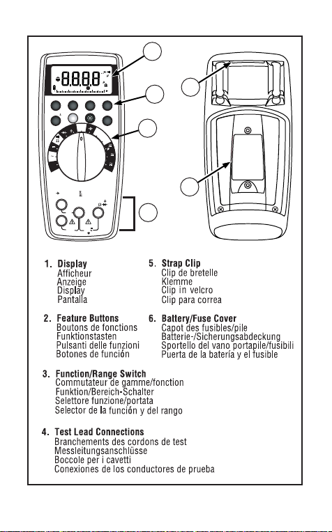
Measuring DC Voltage See Figure -1-
1. Set the Function Switch to @.
2. If RANGE is displayed, press the RANGE button to enable autoranging.
3. Connect the Test Leads: Red to , Black to COM
4. Connect the Test Probes to the circuit test points.
5. Read the display, and, if necessary, correct any overload (
-
) conditions.
Measuring AC Voltage (True rms) See Figure -2 - & -3-
See Additional Features to find out the advantages of true rms.
1. Set the Function Switch to &.
2. If RANGE is displayed, press the RANGE button to enable autoranging.
3. If dBm is displayed, press the yellow button to turn off dBm (enable &)
4. Connect the Test Leads: Red to , Black to COM
5. Connect the Test Probes to the circuit test points.
6. Read the display, and, if necessary, correct any overload (
-
) conditions.
Preparing for Current Measurements
xTurn off circuit power before connecting the test probes.
xAllow the meter to cool between measurements if current measurements
approach or exceeds 10 amps.
xA warning tone sounds if you connect a test lead to a current input before you
select a current function.
xOpen circuit voltage at the measurement point must not exceed 1000 V.
xAlways measure current in series with the load. Never measure current across a
voltage source.
Measuring DC Current See Figure -4-
1. Set the Function Switch to a current function, μA, mA, or 10A.
2. If the 10A function is not selected and RANGE is displayed, press the RANGE
button to enable autoranging.
3. Connect the Test Leads: Red to μA mA or 10A, Black to COM
4. Turn off power to the circuit being measured.
5. Open the test circuit (() to establish measurement points.
6. Connect the Test Probes in series with the load.
7. Turn on power to the circuit being measured.
8. Read the display, and, if necessary, correct any overload (
-
or -) conditions.
Measuring AC Current (True rms) See Figure -3- & -5-
See Additional Features to find out the advantages of true rms.
1. Set the Function Switch to a current function and range, μA, mA, or 10A.
2. If DC is displayed, press the yellow button to turn on AC.
3. If the μA or mA function is not selected and RANGE is displayed, press the
RANGE button to enable autoranging.
4. Connect the Test Leads: Red to μA mA or 10A, Black to COM
5. Turn off power to the circuit being measured.

5
5. Open the test circuit (() to establish measurement points.
6. Connect the Test Probes in series with the load.
7. Turn on power to the circuit being measured.
8. Read the display, and, if necessary, correct any overload (
-
) conditions.
Measuring Resistance See Figure -6-
1. Set the Function Switch to
:
.
2. If
5
is displayed, press the yellow button to display
:
.
3. If RANGE is displayed, press the RANGE button to enable autoranging.
4. Connect the Test Leads: Red to , Black to COM
5. Turn off power to the circuit being measured. Never measure resistance across
a voltage source or on a powered circuit.
6. Discharge any capacitors that may influence the reading.
7. Connect the Test Probes across the resistance.
8. Read the display. If
-
appears on the highest range, the resistance is too large
to be measured.
Testing for Continuity See Figure -7-
1. Set the Function Switch to
5
.
2. If
:
is displayed, press the yellow button to display
5
.
3. Connect the Test Leads: Red to , Black to COM
4. Turn off power to the circuit being measured.
5. Discharge any capacitors that may influence the reading.
6. Connect the Test Probes across the resistance.
7. Listen for the tone that indicates continuity (< 40 :).
Testing Diodes See Figure -8-
1. Set the Function Switch to
*
.
2. Connect the Test Leads: Red to , Black to COM
3. Turn off power to the circuit being measured.
4. Free at least one end of the diode from the circuit.
5. Connect the Test Probes across the diode.
6. Read the display. A good diode has a forward voltage drop of about 0.6 V. An
open or reverse biased diode will read
-
.
Measuring Capacitance See Figure -9-
1. Set the Function Switch to the function.
2. If RANGE is displayed, press the RANGE button to enable autoranging.
3. Connect the Test Leads: Red to COM, Black to mA
4. Turn off power to the circuit being measured.
5. Discharge the capacitor using a 100 k:resistor.
6. Free at least one end of the capacitor from the circuit.
7. Connect the Test Probes across the capacitor. When measuring an electrolytic
capacitor match the test lead polarity to the polarity of the capacitor.
8. Read the display.

6
Measuring Inductance See Figure -10-
1. Set the Function Switch to mH or H.
2. If RANGE is displayed, press the RANGE button to enable autoranging.
3. Connect the Test Leads: Red to H mA, Black to COM
4. Turn off power to the circuit being measured.
5. Free at least one end of the inductor from the circuit.
6. Connect the Test Probes across the inductor.
7. Read the display.
Measuring Frequency See Figure -11-
1. Set the Function Switch to Hz.
2. If % is displayed, press the yellow button to display Hz.
3. If RANGE is displayed, press the RANGE button to enable autoranging.
4. Connect the Test Leads: Red to Hz, Black to COM
5. Connect the Test Probes to the signal source.
6. Read the display.
Measuring Dutycycle See Figure -12-
1. Set the Function Switch to %.
2. If Hz is displayed, press the yellow button to display %.
3. Connect the Test Leads: Red to %, Black to COM
4. Connect the Test Probes to the signal source.
5. Read the display.
Measuring dBm See Figure -13-
The 37XR-A measures dBm relative to 1 mW referenced to 50 :. That is,
10 dBm = 10 mW, 0 dBm = 1 mW, -10 dBm = 0.1 mW, etc.
1. Set the Function Switch to dBm.
2. Press the yellow button. The display shows dBm to verify the selection.
3. Connect the Test Leads: Red to , Black to COM
4. Connect the Test Probes to the signal source.
5. Read the display.
Testing Logic Levels See Figure -14-
The 37XR-A tests logic levels for both TTL and CMOS logic. The meter displays 9
plus a
for a high-level (true) condition. The meter beeps and displays an 9and
a
for a low-level (false) condition. See Specifications for the logic 1 and logic 0
voltage limits. Out-of-limits indications are dispalyed as 9 only, no
or beep
occur.
1. Set the Function Switch to LOGIC
2. Press the TTL CMOS button to display the selected type.
3. Connect the Test Leads: Red to , Black to COM
4. Connect the black lead to logic common.
5. Connect the red lead to the logic test point.
6. Read the display.

7
Additional Features
Input Test Lead Warning
The meter emits a continuous tone when a test lead is placed in the mA or 10A
input jack and the Function/Range Switch is not set to a correct current position. (If
the meter is connected to a voltage source with leads connected for current, very
high current could result). All current ranges are protected by fast acting fuses.
True-rms Measurements
For ac measurements most DMMs average the ac input signal and display the
result as an estimated rms value. This average-responding method is accurate for
sinusoidal waveforms, but can be very inaccurate for distorted waveforms. To
ensure the most accurate measurements, always use a true-rms DMM when
measuring ac voltage or ac current on circuits for the following kinds of
applications:
xPower Supplies - diodes
xControllers
xPower Limiting - SCR or Triac
xStarting - motors
xFlorescent Lighting - ballasts
xSpeed Control - motors
xPulsed Signals
xAny non-sinusoidal ac waveform
MIN MAX AVG Measurements
The MIN MAX AVG function reads and updates the display to show the maximum
or minimum value measured after you press the MIN MAX AVG button.
Pressing the MIN MAX AVG button for less than 1 second will put the meter into a
mode of displaying the maximum, minimum, average, or actual readings. Each time
the button is pressed, the meter will cycle to the next display mode as shown in the
table below. Press the MIN MAX AVG button for more than 2 seconds to disable
this feature.
Button Display Value Displayed
< 1 second REC MAX Maximum value after feature activated
REC MIN Minimum value after feature activated
< 1 second REC AVG Average value after feature is activated
< 1 second REC Actual reading, min max being recorded.
> 2 seconds Exit MIN MAX AVG Normal measurement, actual reading
Peak Hold Measurements
Note: The PEAK function calibrates itself to meet the specifications.
Peak Hold records and stores the positive and negative peak values that occur while
measuring ac current or ac voltage. To enable the Peak Hold feature press the PEAK
button for more than 2 seconds. The display will show CAL to indicate the
calibration cycle is in process. After the CAL indication clears, press the PEAK
button again to display the maximum (P+) value for the ac voltage or ac current
being measured. The display will toggle between the P+ and P- readings each time
the PEAK button is pressed. Press the PEAK button for more than 1 second to exit
the PEAK function.

8
Beeper Off
The beeper is an aural indicator to identify when the DMM is performing a function,
making a range change, detecting a limit, and so on. To disable the beeper use the
following procedure:
1. Set the Function Switch to OFF.
2. Press and hold the HOLD button while turning the Function Switch to the
desired function. The no-beep symbol shows on the display.
3. Release the HOLD button. The Auto Power Off feature will remain disabled until
the meter is turned off and then on.
Note: To disable both the beeper and Auto Power Off press and hold the REL button
while turning on the DMM.
Auto Power Off
Auto Power Off is a battery saving feature that puts the meter into a sleep mode if
the Function/Range Switch has not changed position in the last 30 minutes. To
wake the meter turn it off and then on.
The Auto Power Off feature can be disabled to keep the meter from going to sleep.
This feature is useful when using the MIN MAX mode for extended periods. To
disable the Auto Power Off feature use the following procedure:
1. Set the Function Switch to OFF.
2. Press and hold the MIN MAX AVG button while turning the Function Switch
from OFF to the desired function. The SLEEP OFF message shows on the
display.
3. Release the MIN MAX AVG button. The Auto Power Off feature will remain
disabled until the meter is turned off and then on.
Note: To disable both Auto Power Off and the beeper press and hold the REL button
while turning on the DMM.
REL (Relative) Measurements
The Relative mode displays the difference between the actual reading and a
reference value. It may be used with any function or range. To make a relative
measurement first establish a reference value by measuring a value and then
pressing the REL button after the reading has stabilized. This stores the measured
value as the reference and sets the display to zero. The meter subtracts the
reference value from subsequent measurements and displays this difference as the
relative value. Measurement values greater than the reference value will be positive
and values less than the reference value will be negative.
To exit the Relative Mode, Press and hold the REL button for 2 seconds.
HOLD Measurements
The HOLD button causes the meter to capture and continuously display a
measurement reading. To use the HOLD feature make a measurement, and then,
after the reading has stabilized, momentarily press the HOLD button. You can
remove the test leads and the reading will remain on the display. Pressing the
HOLD button again releases the display.
Backlight
Pressing the button illuminates the display with a blue backlight. The backlight
will automatically turn off in about 60 seconds. Frequent use of the backlight will
decrease battery life.

9
Product Maintenance
Cleaning
To clean the meter, use a soft cloth moistened with water. To avoid damage to the
plastic components do not use benzene, alcohol, acetone, ether, paint thinner,
lacquer thinner, ketone or other solvents to clean the meter.
Troubleshooting
If the meter appears to operate improperly, check the following items first.
1. Review the operating instructions to ensure the meter is being used properly.
2. Inspect and test the continuity of the test leads.
3. Make sure the battery is in good condition. The low battery symbol appears
when the battery falls below the level where accuracy is guaranteed. Replace a
low-battery immediately.
4. Check the condition of the fuses if the current ranges operate incorrectly.
Battery and Fuse Replacement See Figure -15-
;:
WARNING
To avoid electrical shock remove the test leads from both the
meter and the test circuit before accessing the battery or the
fuses.
To access the battery and the mA fuse remove the two screws holding the
Battery/Fuse Cover in place, and lift the cover from the meter.
To replace the mA fuse, pry it from its clips using a small screwdriver. A spare mA
fuse is located between the battery and the mA fuse.
mA Fuse: Fast Blow .5A/1000V, minimum interrupt rating 30 kA
(6.3 x 32 mm) (AmprobeFP500)
To replace the 10 A fuse: 1) Remove the battery. 2) Remove the four rear-case
screws. 3) Separate the case. 4) Remove the 10 A fuse cover. 5) Remove and
replace the 10A fuse. 6) Re-install the fuse cover. 7) Reassemble the meter.
10A Fuse: Fast Blow 10A/1000V, minimum interrupt rating 30 kA
(10 x 38 mm) (AmprobeFP100).

11
Specifications
General Specifications
(Stated accuracy at 23 °C ±5 °C, <75 %
relative humidity.)
Display: 4 ¾ digit liquid crystal display
(LCD) with a 41 segment analog bar-
graphic.
Auto ranging: 9999 counts
Manual ranging: 9999 counts
Polarity: Automatic, positive implied,
negative polarity indication.
Overrange: (OL) or (-OL) is displayed.
Zero: Automatic.
Low battery indication: The is
displayed when the battery voltage
drops below the operating level.
Auto power off: Approx. 30 minutes.
Measurement rate: 2 times per second,
nominal.
Operating environment: 0 °C to 50 °C
at <70 % R.H.
Storage temperature: -20 °C to 60 °C,
0 to 80 % R.H. with battery removed
from meter.
Temperature Coefficient: 0.1 ×
(specified accuracy) per °C. (0 °C to
18 °C, 28 °C to 50 °C).
Altitude: (2000 m) 6562 feet
Power: Single standard 9-volt battery,
NEDA 1604, JIS 006P, IEC 6F22.
Battery life: 75 hours typical with
carbon-zinc. 150 hours typical with
alkaline. Using the backlight will
decrease battery life.
Dimensions:
196 mm (H) ×92 mm (W) ×60 mm (D).
Weight:
with battery and holster, 482 grams
Box contents:
Test leads /w alligator clips 1 set
Users Manual 1
Magne-Grip®Holster 1
Clip, magnet, and strap. 1
9V battery (installed) 1
spare mA fuse 0.5A/1000V 1
Approvals:
Safety: Conforms to EN61010- 1: Cat II –
1000V / Cat III - 600V; Class 2, Pollution
degree II; UL3111-1; CSA C22.2
No. 1010.1, criteria B.
3W
EMC: Conforms to EN61326-1.
This product complies with requirements of
the following European Community
Directives: 89/ 336/ EEC (Electromagnetic
Compatibility) and 73/ 23/ EEC (Low
Voltage) as amended by 93/ 68/ EEC (CE
Marking). However, electrical noise or
intense electromagnetic fields in the vicinity
of the equipment may disturb the
measurement circuit. Measuring
instruments will also respond to unwanted
signals that may be present within the
measurement circuit. Users should exercise
care and take appropriate precautions to
avoid misleading results when making
measurements in the presence of electronic
interference.
Electrical Specifications
DC VOLTS
Ranges: 1000mV, 10V, 100V, 1000V
(Auto/Manual ranging )
Resolution: 100 μV
Accuracy: ±(0.1 % rdg + 5 dgts)
Input impedance: 10 M:
Overload protection: 1000 V dc or 750 V
ac rms
AC VOLTS TRUE RMS (45 Hz - 2 kHz)
Ranges: 1000mV, 10V, 100V, 750V
(Auto/Manual ranging )
Resolution: 100 μV
Minimum reading on 1000mV range:
14 mV
Accuracy:
±(1.2 % rdg + 10 dgts) 45 Hz to 500 Hz
±(2.0% rdg + 10 dgts) 500 Hz to 2 kHz
±(2.0% rdg + 10 dgts) 45 Hz to 1 kHz
on 750 V range

12
Peak Hold accuracy: ±(3.0 % + 200
dgts) on 100V, 750V range
1000mV, 10V ranges unspecified
Crest Factor: d3
Input impedance: 10 M:
AC coupled true rms specified from 5%
to 100% of range
Overload protection: 1000 V dc or 750 V
ac rms
DC CURRENT
Ranges: 100μA, 1000μA, 10mA,
100mA, 400mA, 10A (Auto/Manual
ranging )
Resolution: 0.01 μA
Accuracy:
±(0.5 % rdg +10 dgts) on 100μA range
±(0.5 % rdg + 5 dgt) on 1000μA to
400mA ranges
±(1.5 % rdg + 10 dgts) on 10A range
Input protection: 0.5A/1000V fast blow
ceramic fuse 6.3×32 mm on μA/mA
input
10A/1000V fast blow ceramic fuse
10×38 mm on 10A input
10A input: 10 A for 4 minutes maximum
followed by a 12 minute cooling period
Burden voltage:
PA Range: 1 mV/ 1 PA
mA Range: 10 mV/ 1 mA
A Range: 35 mV/ 1 A
AC CURRENT TRUE RMS (45 Hz to
1 kHz)
Ranges:100μA, 1000μA, 10mA, 100mA,
400mA, 10A (Auto/Manual ranging )
Resolution: 0.01 μA
Accuracy:
±(1.5% rdg +10 dgts) on 100μA to
100mA ranges
±(2.0% rdg +10 dgts) on 400mA range
±(2.5% rdg + 20 dgts) on 10A range
Peak Hold accuracy: ±(3.0 % + 200
dgts) 100μA range unspecified
Crest Factor: 3 d
AC coupled true rms specified from 5 %
to 100 % of range
Input protection: 0.5A/1000V fast blow
ceramic fuse 6.3×32 mm on μA/mA
input
10A/1000V fast blow ceramic fuse
10×38 mm on 10A input
10A input: 10 A for 4 minutes maximum
followed by a 12 minute cooling period
Burden voltage: See DC Current
RESISTANCE
Ranges: 1000:, 10k:, 100k:,
1000k:, 10M:, 40M:(Auto/Manual
ranging )
Resolution: 100 m:
Accuracy: ±(0.5% rdg + 8 dgts) on
1000:to 1000k:ranges
±(1.0% rdg + 10 dgts) on 10M:range
±(2.0% rdg + 10 dgts) on 40M:range
Open circuit volts: -0.45 V dc typical
Overload protection: 1000 V dc or 750 V
ac rms
CAPACITANCE
Ranges: 40nF, 400nF, 4μF, 40μF 400uF
(3999 counts) (Auto/Manual ranging )
Resolution: 0.01 nF
Accuracy: ±(3.0 % rdg + 10 dgts) on
40nF, 400uF ranges
±(3.0 % rdg + 5 dgts) on 400nF to 40uF
ranges
Test voltange: < 1 V
Test Frequency: 1.3 Hz on 40nF to 40μF
ranges; 0.7 Hz on 400μF range
Input protection: 0.5A/1000V fast blow
ceramic fuse 6.3×32 mm on μA/mA
input
INDUCTANCE
Ranges: 4mH, 40mH, 400mH, 4H, 40H
( 3999 counts ) (Auto/Manual ranging )
Resolution: 1 μH
Accuracy: ±(5.0 % rdg + 30 dgts)*
*For values of Q d7
Test frequecy: 1 kHz on 4mH, 40mH
ranges, 200 Hz on 400mH to 40H
ranges.
Input protection: 0.5A/1000V fast blow
ceramic fuse 6.3×32 mm on μA/mA
input

13
FREQUENCY
Ranges: 100Hz, 1000Hz, 10kHz, 100kHz,
1000KHz, 10MHz, (Auto/Manual ranging )
Resolution: 0.01 Hz
Accuracy: ±(0.1 % rdg + 5 dgts)
Sensitivity: 3Hz to 1MHz: >1.5 V rms; 1MHz
to 10MHz: >2 V rms, <5 V rms
Minimum input range: 100Hz range > 3 Hz,
1000Hz range > 30 Hz
Minimum pulse width: > 25 ns
Duty cycle limits: > 30 % and < 70 %
Overload protection: 1000 V dc or 750 V ac
rms
DUTY CYCLE
Ranges: 0 to 90 %
Resolution: 0.01 %
Pulse width:>10 us
Frequency range:
0% to 10% (40 Hz to 20 kHz)
10% to 90% (40 Hz to 990 Hz)
Accuracy: (5 V logic ) ±(2.0 % rdg + 20
dgts)
Overload protection: 1000 V dc or 750 V ac
rms
LOGIC TEST
Logic Type: TTL, CMOS
Thresholds Logic 1 ( Hi ):
TTL : 2.8 V ± 0.8 V, CMOS: 4 V ± 1 V
Thresholds Logic 0 ( Lo ):
TTL : 0.8 V ± 0.5 V, CMOS: 2 V ± 0.5 V
Test Voltage: TTL: 5 V dc, CMOS: > 5 V dc
and < 10 V dc
Frequency Response: 20 MHz
Pulse Width: 25 ns min
Duty Cycle: >30 % and <70 %
Indication: 40 ms beep at logic 0 ( LO )
Overload protection: 1000 V dc or 750 V ac
rms
dBm
Ranges: -13dBm to + 50dBm
Resolution: 0.01 dBm
Accuracy:
±0.7 dB + 8 dgts ( 45 Hz to 5 kHz )
±2.5 dB + 8 dgts ( 5 kHz to 10 kHz )
Reference impedance: 50 :
Input protection: 10 M:
Overload protection: 1000 V dc or 750 V
ac rms
CONTINUITY
Audible indication: Less than 40:
Response time: 100 ms
Overload protection:1000 V dc or 750 V
ac rms
DIODE TEST
Test current: 1.0 mA (approximate)
Accuracy: ±(1.5 % rdg + 5 dgts)
Resolution: 1 mV
Open circuit volts: 3.0 dc typical
Overload protection:
1000 V dc or 750 V ac rms
mA, 10A jack: Input warning detects
wrong function selection
AUXILIARY FEATURES
MIN/AVG/MAX: Displays the maximum,
minimum, or average reading following
a MIN, MAX, or AVG selection.
DATA HOLD: Freeze the latest reading
on the display.
REL: Initiates relative measurements.
PEAKr: Record the peak+ or peak
value in a measurement. It is usable
with ac voltage, ac current
measurements. If the pressed time >2
seconds, the PEAK function will enter
the calibration mode; the LCD will show
CAL and the internal buffer will
remember the internal offset voltage
then go back to the measure mode.
RANGE: Initiates manual-range
selection.
Backlight: Backlight auto-off approx. 60
seconds
TTL/CMOS: Shift LOGIC TTL or CMOS
Shift: Shift dBm, ACA, continuity, DUTY
CYCLE
REPLACEMENT PARTS
TL36 Test Lead Set with Alligator clips
FP500 mA fuse - Fuse Pack 0.5A/1000V
(4 each)
FP100 10A fuse - Fuse Pack 10A/1000V
(2 each)
XR-H2 Magne-Grip®Holster, clip, magnet,
and strap

14
5
4
1
4
3
1
1
2
3
2
6
V
V
2
5
37XR-A
37XR-A

7
Input Waveform
Signal d'entrée
Eingangsschwingungsform
Forma d'onda d'ingresso
Forma de onda de entrada
Sine Wave
Sinusoïdale
Sinusschwingung
Onda sinusoidale
Onda sinusoidal
Full Wave, Sine Wave
Onde complète, Sinusoïdale
Volle Schwingung, Sinusschwingung
Onda sinusoidale, onda intera
Onda completa, Onda sinusoidal
Half-Wave, Sine Wave
Demi-onde, sinusoïdale
Halbschwingung, Sinusschwingung
Onda sinusoidale, semionda
Media onda, onda sinusoidal
Square Wave
Onde carrée
Rechteckschwingung
Onda quadra
Onda cuadrada
Square Wave
Onde carrée
Rechteckschwingung
Onda quadra
Onda cuadrada
Pulse Wave
Onde impulsionnelle
Impulsschwingung
Onda delI'impulso
Onda de impulsos
Sawtooth Wave
Onde en dent de scie
Sägezahnschwingung
Onda a denti di sega
Onda diente de sierra
37XR-A

16
5
47
5
6
58
6
7
A
1
3
4
1
4
2
2
8
A
3
9
37XR-A
37XR-A

17
5
7
6
6
4
5
7
4
1
6
7
3
1
2
2
3
8
37XR-A
37XR-A

18
2
8
1
3
5
4
1
5
6
7
3
9
4
8
2
6
37XR-A
37XR-A
Other manuals for 37XR-A
1
Table of contents
Other Amprobe Multimeter manuals

Amprobe
Amprobe HD160C User manual

Amprobe
Amprobe HD160C User manual

Amprobe
Amprobe AM-420 User manual

Amprobe
Amprobe AM-540 User manual

Amprobe
Amprobe AMP-210 User manual

Amprobe
Amprobe CDM-1 User manual

Amprobe
Amprobe AM90 User manual

Amprobe
Amprobe 15XP-A User manual

Amprobe
Amprobe AM-120 TRMS User manual

Amprobe
Amprobe AD40B Operating instructions

Amprobe
Amprobe PM53A User manual

Amprobe
Amprobe AC71B User manual

Amprobe
Amprobe AM-6B User manual

Amprobe
Amprobe PM-60 User manual

Amprobe
Amprobe 5XP-A User manual

Amprobe
Amprobe AM-510-EUR User manual

Amprobe
Amprobe 34XR-A User manual

Amprobe
Amprobe ACDC-600A User manual

Amprobe
Amprobe AM-510 User manual

Amprobe
Amprobe 33XR-A User manual