Benning CM11 User manual

CAT IV
300V
COMV Ω
OFF
CM 11
20A
10A
TRUE RMS
Ω
/ Ω
ZERO MIN
MAX HOLD
300V
CAT IV
BENNING CM 11
DBedienungsanleitung
Operating manual
FNotice d‘emploi
EInstrucciones de servicio
Návod k obsluze
Εγχειρίδιο λειτουργίας
IIstruzioni d’uso
Gebruiksaanwijzing
Instrukcja obsługi
Руководство по эксплуатации
Kullanma Talımati

11/ 2014
BENNING CM 11
D
F E I
CAT IV
300V
COMV Ω
OFF
CM 11
20A
10A
TRUE RMS
Ω
/ Ω
ZERO MIN
MAX HOLD
300V
CAT IV
Bild 1: Gerätefrontseite
Fig. 1: Appliance front face
Fig. 1: Partie avant de l‘appareil
Fig. 1: Parte frontal del equipo
Obr. 1: Přední strana přístroje
Σικόνα 1: Μπροστινή όψη
Ill. 1: Lato anteriore apparecchio
Fig. 1: Voorzijde van het apparaat
Rys. 1: Panel przedni przyrządu
Рис. 1: Вид спереди
Resim 1: Cihaz önyüzü
2
7
5
6
9
J
L
8
K

11/ 2014
BENNING CM 11
D
F E I
CAT IV
300V
COMV Ω
OFF
CM 11
20A
10A
TRUE RMS
Ω
/ Ω
ZERO MIN
MAX HOLD
300V
CAT IV
CAT IV
300V
COMV Ω
OFF
CM 11
20A
10A
TRUE RMS
Ω
/ Ω
ZERO MIN
MAX HOLD
300V
CAT IV
Bild 2: Gleichspannungsmessung
Fig. 2: DC voltage measurement
Fig. 2: Mesure de tension continue
Fig. 2: Medición de tensión contínua
obr. 2: Měření stejnosměrného napětí
σχήμα 2: μέτρηση DC-τάσης
ill. 2: Misura tensione continua
Fig. 2: Meten van gelijkspanning
Rys.2: Pomiar napięcia stałego
Рис. 2. Измерение напряжения постоянного тока
Resim 2: Doğru Gerilim Ölçümü
Bild 3: Wechselspannungsmessung
Fig. 3: AC voltage measurement
Fig. 3: Mesure de tension alternative
Fig. 3: Medición de tensión alterna
obr. 3: Měření střídavého napětí
σχήμα 3: μέτρηση AC-τάσης
ill. 3: Misura tensione alternata
Fig. 3: Meten van wisselspanning
Rys.3: Pomiar napięcia przemiennego
Рис. 3. Измерение напряжения переменного тока
Resim 3: Alternatif Gerilim Ölçümü

11/ 2014
BENNING CM 11
D
F E I
CAT IV
300V
COMV Ω
OFF
CM 11
20A
10A
TRUE RMS
Ω
/ Ω
ZERO MIN
MAX HOLD
300V
CAT IV
CAT IV
300V
COMV Ω
OFF
CM 11
20A
10A
TRUE RMS
Ω
/ Ω
ZERO MIN
MAX HOLD
300V
CAT IV
Bild 4: Gleich-/ Wechselstrommessung
Fig. 4: AC/ DC current measurement
Fig. 4: Mesure de courant continue/ courant alternatif
Fig. 4: Medición de corriente contínua/ corriente alterna
obr. 4: Měření stejnosměrného/ střídavého proudu
σχήμα 4: AC/ DC μέτρηση ρεύματος
ill. 4: Misura corrente continua/ alternata
Fig. 4: Meten van wissel- en gelijkstroom
Rys.4: Pomiar prądu stałego/ przemiennego
Рис. 4. Измерение постоянного и переменного тока
Resim 4: Doğru Akım/ Alternatif Akım Ölçümü
Bild 5: Widerstandsmessung
Fig. 5: Resistance measurement
Fig. 5: Mesure de résistance
Fig. 5: Medición de resistencia
obr. 5: Měření odporu
σχήμα 5: Μέτρηση αντίστασης
ill. 5: Misura di resistenza
Fig. 5: Weerstandsmeting
Rys.5: Pomiar rezystancji
Рис. 5. Измерение сопротивления
Resim 5: Direnç Ölçümü

11/ 2014
BENNING CM 11
D
F E I
CAT IV
300V
COMV Ω
OFF
CM 11
20A
10A
TRUE RMS
Ω
/ Ω
ZERO MIN
MAX HOLD
300V
CAT IV
Bild 6: Durchgangsprüfung mit Summer
Fig. 6: Continuity Testing with buzzer
Fig. 6: Contrôle de continuité avec roneur
Fig. 6: Control de continuidad con vibrador
Obr.6: Měření průchodnosti s bzučákem
σχήμα 6: Έλεγχος συνέχειας με ηχητικό σήμα
ill. 6: Prova di continuità con cicalino
Fig. 6: Doorgangstest met akoestisch signaal
Rys.6: Sprawdzenie ciągłości obwodu
Рис. 6. Контроль прохождения тока с зуммером
Resim 6: Sesli Süreklilik Ölçümü
Bild 7: Batteriewechsel
Fig. 7: Battery replacement
Fig. 7: Remplacement des piles
Fig. 7: Cambio de pila
obr. 7: Výměna baterií
σχήμα 7: Αντικατάσταση μπαταριών
ill. 7: Sostituzione batterie
Fig. 7: Vervanging van de batterijen
Rys.7: Wymiana baterii
Рис. 7. Замена батарейки
Resim 7: Batarya Değişimi

11/ 2014
BENNING CM 11
1
D
Bedienungsanleitung
BENNING CM 11
TRUE RMS Digital-Stromzangen-Multimeter zur
- Gleich-/ Wechselspannungsmessung
- Gleich-/ Wechselstrommessung
- Widerstandsmessung
- Durchgangsprüfung
Inhaltsverzeichnis
1. Benutzerhinweise
2. Sicherheitshinweise
3. Lieferumfang
4. Gerätebeschreibung
5. Allgemeine Angaben
6. Umgebungsbedingungen
7. Elektrische Angaben
8. Messen mit dem BENNING CM 11
9. Instandhaltung
10. Technische Daten des Messzubehörs
11. Umweltschutz
1. Benutzerhinweise
Diese Bedienungsanleitung richtet sich an
- Elektrofachkräfte und
- elektrotechnisch unterwiesene Personen
Das BENNING CM 11 ist zur Messung in trockener Umgebung vorgesehen und darf nicht in
Stromkreisen mit einer höheren Nennspannung als CAT IV 300 V eingesetzt werden (Näheres
hierzu in Abschnitt 6. “Umgebungsbedingungen”).
In der Bedienungsanleitung und auf dem BENNING CM 11 werden folgende Symbole ver-
wendet:
Anlegen um GEFÄHRLICH AKTIVE Leiter oder Abnehmen von diesen ist zuge-
lassen.
Dieses Symbol weist auf elektrische Gefahr hin.
Dieses Symbol weist auf Gefährdungen beim Gebrauch des BENNING CM 11 hin.
(Dokumentation beachten!)
Dieses Symbol auf dem BENNING CM 11 bedeutet, dass das Gerät schutzisoliert
(Schutzklasse II) ausgeführt ist.
Dieses Symbol erscheint in der Anzeige für eine entladene Batterie.
Dieses Symbol kennzeichnet den Bereich “Durchgangsprüfung”. Der Summer
dient der akustischen Ergebnisausgabe.
(DC) Gleich- Spannung oder Strom.
(AC) Wechsel- Spannung oder Strom.
Masse (Spannung gegen Erde).

11/ 2014
BENNING CM 11
2
D
2. Sicherheitshinweise
Das Gerät ist gemäß
DIN VDE 0411 Teil 1/EN 61010-1
DIN VDE 0411 Teil 2-032/EN 61010-2-032
DIN VDE 0411 Teil 031/EN 61010-031
gebaut und geprüft und hat das Werk in einem sicherheitstechnisch einwandfreien Zustand
verlassen.
Um diesen Zustand zu erhalten und einen gefahrlosen Betrieb sicherzustellen, muss der
Anwender die Hinweise und Warnvermerke beachten, die in dieser Anleitung enthalten sind.
Fehlverhalten und Nichtbeachtung der Warnungen kann zu schwerwiegenden Verletzungen
oder zum Tode führen.
Extreme Vorsicht bei Arbeiten um blanke Leiter oder Hauptleitungsträger. Ein
Kontakt mit Leitern kann einen Elektroschock verursachen.
Das Gerät darf nur in Stromkreisen der Überspannungskategorie III und IV mit
max. 300 V gegen Erde benutzt werden.
Hierzu sind geeignete Messleitungen zu verwenden. Bei Messungen innerhalb
der Messkategorie III und IV darf das hervorstehende leitfähige Teil einer
Kontaktspitze der Messleitung nicht länger als 4 mm sein. Vor Messungen
innerhalb der Messkategorie III und IV müssen, die dem Set beigestellten, mit
CAT III und CAT IV gekennzeichneten, Aufsteckkappen auf die Kontaktspitzen
aufgesteckt werden. Diese Maßnahme dient dem Benutzerschutz.
Beachten Sie, dass Arbeiten an spannungsführenden Teilen und Anlagen
grundsätzlich gefährlich sind. Bereits Spannungen ab 30 V AC und 60 V DC
können für den Menschen lebensgefährlich sein.
Vor jeder Inbetriebnahme überprüfen Sie das Gerät und die Leitungen auf
Beschädigungen.
Ist anzunehmen, dass ein gefahrloser Betrieb nicht mehr möglich ist, ist das Gerät außer Betrieb
zu setzen und gegen unbeabsichtigten Betrieb zu sichern.
Es ist anzunehmen, dass ein gefahrloser Betrieb nicht mehr möglich ist,
- wenn das Gerät oder die Messleitungen sichtbare Beschädigungen aufweisen,
- wenn das Gerät nicht mehr arbeitet,
- nach längerer Lagerung unter ungünstigen Verhältnissen,
- nach schweren Transportbeanspruchungen,
- wenn das Gerät und die Messleitungen feucht sind.
3. Lieferumfang
Zum Lieferumfang des BENNING CM 11 gehören:
3.1 ein Stück Digital-Stromzangen-Multimeter,
3.2 ein Stück Sicherheitsmessleitung, schwarz (L = 1,4 m),
3.3 ein Stück Sicherheitsmessleitung, rot (L = 1,4 m),
3.4 eine Stück Kompakt-Schutztasche,
3.5 zwei Stück 1,5-V-Micro-Batterien (IEC LR03/ AAA),
3.6 eine Bedienungsanleitung.
Hinweis auf Verschleißteile:
- Das BENNING CM 11 wird von zwei 1,5-V-Micro-Batterien (IEC LR03/ AAA) gespeist.
- Die oben genannten Sicherheitsmessleitungen (geprüftes Zubehör) entsprechen CAT III
1000 V/CAT IV 600 V und sind für einen Strom von 10 A zugelassen.
4. Gerätebeschreibung
Das BENNING CM 11 ist ein Digital-Stromzangen-Multimeter mit einem Hallsensor bestückten
Strommesskopf
siehe Bild 1: Gerätefrontseite
Die in Bild 1 angegebenen Anzeige- und Bedienelemente werden wie folgt bezeichnet:
Messzange, zum Umfassen des einadrigen stromdurchflossenen Leiters,
2Stromzangenwulst, schützt vor Leiterberührung,
-Taste (gelb), Displaybeleuchtung,
Öffnungshebel, zum Öffnen und Schließen der Stromzange,
5Drehschalter, zur Wahl der Messfunktion,
6ZERO-Taste, für Nullabgleich bzw. Differenzmessung
7MIN/ MAX-Taste, Speicherung des niedrigsten und höchsten Messwertes,

11/ 2014
BENNING CM 11
3
D
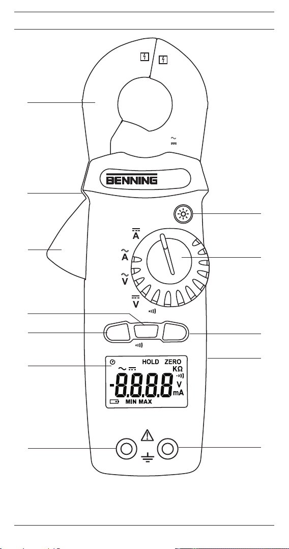
8HOLD-Taste, Speicherung des angezeigten Messwertes,
9Digitalanzeige, für den Messwert und die Anzeige der Bereichsüberschreitung,
JCOM-Buchse, gemeinsame Buchse für Spannungs-, Widerstandsmessungen und Durch-
gangsprüfung, schwarz markiert.
KV-Ω-Buchse (positive), gemeinsame Buchse für Spannungs-, Widerstandsmessungen und
Durchgangsprüfung, rot markiert.
LBatteriefachdeckel, auf Gehäuserückseite
5. Allgemeine Angaben
5.1 Allgemeine Angaben zum Digital-Stromzangen-Multimeter
5.1.1 Die Digitalanzeige 9ist als 4-stellige Flüssigkristallanzeige mit 12 mm Schrifthöhe mit
Dezimalpunkt ausgeführt. Der größte Anzeigewert ist 5000.
5.1.2 Die Polaritätsanzeige in der Digitalanzeige 9wirkt automatisch. Es wird nur eine
Polung entgegen der Buchsendefinition mit “-” angezeigt.
5.1.3 Die Bereichsüberschreitung wird mit “0L.” angezeigt.
Achtung, keine Anzeige und Warnung bei Überlast!
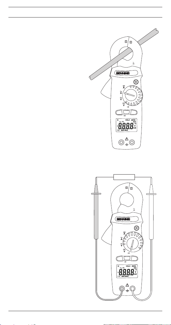
5.1.4 Der Drehschalter 5dient der Anwahl der Messfunktion.
5.1.5 ZERO-Tastenfunktion 6: Zum Nullabgleich bei Strommessungen, kann auch für alle
Bereiche zur Differenzmessung benutzt werden (Nullabgleich bei jedem Wert möglich!).
Angezeigt durch “ZERO” in der Digitalanzeige 9,
5.1.6 Die MIN/ MAX-Tastenfunktion 7erfasst und speichert automatisch den niedrigsten und
höchsten Messwert. Durch Weiterschaltung werden folgende Werte angezeigt: Anzeige
„MAX“ zeigt den gespeicherten höchsten, „MIN“ den niedrigsten Wert und „MIN/ MAX“
zeigt den aktuellen Messwert an. Durch längeren Tastendruck (2 Sekunden) wird in den
Normalmodus zurückgeschaltet.
In der Messfunktion / Ω wechselt eine Betätigung der MIN/ MAX Taste 7von der
akustischen Durchgangsprüfung zur Widerstandsmessung.
5.1.7 HOLD-Tastenfunktion: Durch Betätigen der HOLD-Taste 8lässt sich das Messergebnis
speichern. Im Display 9wird gleichzeitig das Symbol „HOLD“ eingeblendet. Erneutes
Betätigen der Taste schaltet in den Messmodus zurück.
5.1.8 Die gelbe Beleuchtungs-Taste schaltet die Beleuchtung des Displays 9an. Aus-
schaltung durch erneute Tastenbetätigung oder automatisch nach ca. 30 s.
5.1.9 Die Messrate des BENNING CM 11 beträgt nominal 2 Messungen pro Sekunde für die
Digitalanzeige.
5.1.10 Das BENNING CM 11 wird durch den Drehschalter 5ein- oder ausgeschaltet. Aus-
schaltstellung “OFF”.
5.1.11 Das BENNING CM 11 schaltet sich nach ca. 15 min selbsttätig ab (APO, Auto-Power-
Off ist aktiv bei Einblendung des -Symbol in der Anzeige 9). Es schaltet sich wieder
ein, wenn der Drehschalter 5 aus der Schalterstellung “OFF” wieder eingeschaltet
oder die gelbe Beleuchtungstaste betätigt wird. Die automatische Abschaltung
lässt sich deaktivieren indem sie die HOLD-Taste 8betätigen und gleichzeitig das
BENNING CM 11 aus der Schalterstellung “OFF” einschalten. Das -Symbol in der
Anzeige 9erlischt.
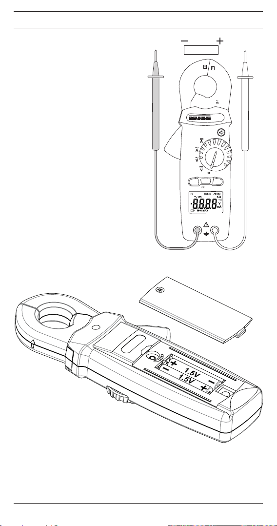
5.1.12 Das BENNING CM 11 wird durch zwei 1,5-V-Micro-Batterien gespeist (IEC LR03/AAA).
5.1.13 Wenn die Batteriespannung unter die vorgesehene Arbeitsspannung des
BENNING CM 11 sinkt, erscheint in der Anzeige 9ein Batteriesymbol.
5.1.14 Die Lebensdauer der Batterien ist abhängig der genutzten Messfunktion und
beträgt ca. 30-100 Stunden ohne Nutzung der akustischen Durchgangsprüfung und
Hintergrundbeleuchtung. (Alkalibatterie).
5.1.15 Temperaturkoeffizient des Messwertes:
0,1 x (angegebene Messgenauigkeit)/ °C < 18 °C oder > 28 °C, bezogen auf den Wert
auf Referenztemperatur von 23 °C.
5.1.16 Geräteabmessungen: (L x B x H) = 206 x 76 x 33,5 mm
Gerätegewicht: 262 g (inkl. Batterien)
5.1.17 Die mitgelieferten Sicherheitsmessleitungen mit den Messspitzen sind ausdrücklich
für die Nennspannung des BENNING CM 11 geeignet. Die Messspitzen können durch
Schutzkappen geschützt werden.
5.1.18 Größte Zangenöffnung: 23 mm
6. Umgebungsbedingungen
- Das BENNING CM 11 ist für Messungen in trockenen Umgebungen vorgesehen,
- Barometrische Höhe bei Messungen: Maximal 2000 m,
- Überspannungskategorie: IEC 60664/IEC 61010 → 300 V Kategorie IV
- Verschmutzungsgrad: 2 gemäß EN 61010-1,
- Schutzart: IP 30 (DIN VDE 0470-1 IEC/EN 60529)
3 - erste Kennziffer: Schutz gegen Zugang zu gefährlichen Teilen und Schutz gegen feste
Fremdkörper, > 2,5 mm Durchmesser

11/ 2014
BENNING CM 11
4
D
0 - zweite Kennziffer: Kein Wasserschutz,
- Arbeitstemperatur und relative Luftfeuchte:
Bei Arbeitstemperatur von 0 °C bis 40 °C: relative Luftfeuchte kleiner 80 %, nicht kondensierend.
- Lagerungstemperatur: Das BENNING CM 11 kann bei Temperaturen von - 10 °C bis
+ 60 °C, relative Luftfeuchte kleiner 80 %, ohne Batterien gelagert werden.
7. Elektrische Angaben
Bemerkung: Die Messgenauigkeit wird angegeben als Summe aus
- einem relativen Anteil des Messwertes und
- einer Anzahl von Digit (d.h. Zahlenschritte der letzten Stelle).
Die Messgenauigkeit gilt bei einer Temperatur von 23 °C ± 5 °C und einer relativen
Luftfeuchtigkeit kleiner 80 %.
7.1 Gleichspannungsbereiche
Der Eingangswiderstand beträgt ≥ 1 MΩ.
Messbereich Auflösung Messgenauigkeit Überlastschutz
50,00 V 0,01 V ± (1 % des Messwertes + 2 Digit) 400 V AC/DC
300,0 V 0,1 V ± (1 % des Messwertes + 2 Digit) 400 V AC/DC
7.2 Wechselspannungsbereiche
Der Messwert wird als echter Effektivwert (TRUE RMS, AC-Kopplung) gewonnen und ange-
zeigt. Seine Kalibrierung ist auf sinusförmige Kurvenform abgestimmt. Bei Abweichungen von
dieser Form wird der Anzeigewert ungenauer.
Crest-Factor < 2,0 bis 100 % der Messbereichsendwertes
Crest-Factor < 4,0 bis 50 % der Messbereichsendwertes
Der Eingangswiderstand beträgt ≥ 1 MΩ.
Messbereich Auflösung Messgenauigkeit (40 Hz - 1 kHz) Überlastschutz
50,00 V 0,01 V ± (1,2 % des Messwertes + 5 Digit) 400 V AC/DC
300,0 V 0,1 V ± (1,2 % des Messwertes + 5 Digit) 400 V AC/DC
7.3 Gleichstrombereiche
Messbereich Auflösung Messgenauigkeit Überlastschutz
300,0 mA 0,1 mA ± (1,0 % des Messwertes + 10 Digit) 100 A AC/DC
3,000 A 0,001 A ± (1,0 % des Messwertes + 10 Digit) 100 A AC/DC
10,00 A 0,01 A ± (3,0 % des Messwertes + 10 Digit) 100 A AC/DC
Einfluss des Erdmagnetismus: < ± 1,0 mA
Einfluss des Öffnen und Schließen der Messzange: < ± 1,0 mA
7.4 Wechselstrombereiche
Der Messwert wird als echter Effektivwert (TRUE RMS, AC-Kopplung) gewonnen und ange-
zeigt. Seine Kalibrierung ist auf sinusförmige Kurvenform abgestimmt. Bei Abweichungen von
dieser Form wird der Anzeigewert ungenauer.
Crest-Factor < 2,0 bis 100 % der Messbereichsendwertes
Crest-Factor < 4,0 bis 50 % der Messbereichsendwertes
Messbereich Auflösung Messgenauigkeit (50 Hz - 60 Hz) Überlastschutz
300,0 mA 0,1 mA ± (1,0 % des Messwertes + 5 Digit) 100 A AC/DC
3,000 A 0,001 A ± (1,0 % des Messwertes + 5 Digit) 100 A AC/DC
20,00 A 0,01 A ± (1,0 % des Messwertes + 5 Digit) 100 A AC/DC
7.5 Widerstandsbereiche
Leerlaufspannung: ca. 3 V, max. Prüfstrom 1 mA.
Messbereich Auflösung Messgenauigkeit (50 Hz - 60 Hz) Überlastschutz
500,0 Ω 0,1 Ω ± (1,0 % des Messwertes + 2 Digit) 400 VAC/DC
5,000 kΩ 1 Ω ± (1,0 % des Messwertes + 2 Digit) 400 VAC/DC
50,00 kΩ 10 Ω ± (1,0 % des Messwertes + 2 Digit) 400 VAC/DC
500,0 kΩ 100 Ω ± (1,0 % des Messwertes + 2 Digit) 400 VAC/DC

11/ 2014
BENNING CM 11
5
D
7.6 Durchgangsprüfung
Leerlaufspannung: ca. 3 V, max. Prüfstrom 1 mA.
Der eingebaute Summer ertönt bei einem Widerstand kleiner 100 Ω.
8. Messen mit dem BENNING CM 11
8.1 Vorbereiten der Messungen
Benutzen und lagern Sie das BENNING CM 11 nur bei den angegebenen Lager- und Arbeits-
temperaturbedingungen, vermeiden Sie dauernde Sonneneinstrahlung.
- Angaben von Nennspannung und Nennstrom auf den Sicherheitsmessleitungen überprü-
fen. Die zum Lieferumfang gehörenden Sicherheitsmessleitungen entsprechen in Nenn-
spannung und Nennstrom dem BENNING CM 11.
- Isolation der Sicherheitsmessleitungen überprüfen. Wenn die Isolation beschädigt ist, dann
sind die Sicherheitsmessleitungen sofort auszusondern.
- Sicherheitsmessleitungen auf Durchgang prüfen. Wenn der Leiter in der Sicherheitsmess-
leitung unterbrochen ist, dann ist die Sicherheitsmessleitung sofort auszusondern.
- Bevor am Drehschalter 5eine andere Messfunktion gewählt wird, müssen die Sicherheits-
messleitungen von der Messstelle getrennt werden.
- Starke Störquellen in der Nähe des BENNING CM 11 können zu instabiler Anzeige und zu
Messfehlern führen.
8.2 Spannungsmessung
Maximale Spannung gegen Erdpotential beachten!
Elektrische Gefahr!
Die höchste Spannung, die an den Buchsen
- COM-Buchse J, schwarz markiert,
-
V-Ω-Buchse (positive) Kfür Spannungs-, Widerstandsmessungen und Durchgangsprü-
fungen, rot markiert,
des BENNING CM 11 gegenüber Erdpotential liegen darf, beträgt 300 V.
- Mit dem Drehschalter 5des BENNING CM 11 die gewünschte Funktion V oder V
wählen.
- Die schwarze Sicherheitsmessleitung mit der COM-Buchse J, schwarz gekennzeichnet,
kontaktieren.
- Die rote Sicherheitsmessleitung mit der V-Ω-Buchse K, rot gekennzeichnet, kontaktieren.
- Die Sicherheitsmessleitungen mit den Messpunkten kontaktieren, den Messwert an der
Digitalanzeige 9ablesen.
Hinweis:
- In kleinen Spannungsmessbereichen unterbleibt bei offenen Sicherheitsmessleitungen
die Null-Volt-Anzeige durch Einstreuungen. Überzeugen Sie sich durch Kurzschluss der
Messspitzen davon, dass das BENNING CM 11 funktionsfähig ist.
siehe Bild 2: Gleichspannungsmessung
siehe Bild 3: Wechselspannungsmessung
8.3 Strommessung
Keine Spannung an die Eingangsbuchsen Jund Kdes BENNING CM 11 legen!
Entfernen Sie eventuell die angeschlossenen Sicherheitsmessleitungen. Bei
Gleichstrommessungen Polarität beachten! Der Pfeil auf der Messzange zeigt
die technische Stromrichtung an. + → –
- Mit dem Drehschalter 5die gewünschte Funktion A oder Awählen.
- Durch die Nullabgleichtaste „ZERO“ 6das BENNING CM 11 in Ausgangsposition bringen.
- Öffnungshebel betätigen, einadrigen Leiter mittig mit der Zange des BENNING CM 11
umfassen.
- Die Digitalanzeige 9ablesen.
siehe Bild 4: Gleich-/ Wechselstrommessung
8.4 Widerstandsmessung
- Mit dem Drehschalter 5des BENNING CM 11 die Funktion / Ω wählen und die MIN/
MAX-Taste 7betätigen.
- Die schwarze Sicherheitsmessleitung mit der COM-Buchse J, schwarz gekennzeichnet,
kontaktieren.
- Die rote Sicherheitsmessleitung mit der V-Ω-Buchse K, rot gekennzeichnet, kontaktieren.
- Die Sicherheitsmessleitungen mit den Messpunkten kontaktieren, den Messwert an der
Digitalanzeige 9ablesen.

11/ 2014
BENNING CM 11
6
D
Hinweis:
- Stellen Sie für eine richtige Messung sicher, dass an der Messstelle keine Spannung
anliegt.
siehe Bild 5: Widerstandsmessung
8.5 Durchgangsprüfung mit Summer
- Mit dem Drehschalter 5die Funktion / Ω wählen.
- Die schwarze Sicherheitsmessleitung mit der COM-Buchse J, schwarz gekennzeichnet,
kontaktieren.
- Die rote Sicherheitsmessleitung mit der V-Ω-Buchse K, rot gekennzeichnet, kontaktieren.
- Die Sicherheitsmessleitungen mit den Messpunkten kontaktieren. Wenn der Widerstand
zwischen den Messpunkten 100 Ω unterschreitet, dann ertönt der in dem BENNING CM 11
eingebaute Summer.
siehe Bild 6: Durchgangsprüfung mit Summer
9. Instandhaltung
Vor dem Öffnen das BENNING CM 11 unbedingt spannungsfrei machen!
Elektrische Gefahr!
Die Arbeit an dem geöffneten BENNING CM 11 unter Spannung ist ausschließlich Elektro-
fachkräften vorbehalten, die dabei besondere Maßnahmen zur Unfallverhütung treffen
müssen.
So machen Sie das BENNING CM 11 spannungsfrei, bevor Sie das Gerät öffnen:
- Entfernen Sie zuerst das BENNING CM 11 und die beiden Sicherheitsmessleitungen vom
Messobjekt.
- Entfernen Sie dann beide Sicherheitsmessleitungen vom BENNING CM 11.
- Schalten Sie den Drehschalter 5in die Schaltstellung “OFF”.
Das BENNING CM 11 besitzt keine Sicherung.
9.1 Sicherstellen des Gerätes
Unter bestimmten Voraussetzungen kann die Sicherheit im Umgang mit dem BENNING CM 11
nicht mehr gewährleistet sein, z.B. bei:
- Sichtbaren Schäden am Gehäuse,
- Fehlern bei Messungen,
- Erkennbaren Folgen von längerer Lagerung unter unzulässigen Bedingungen und
- Erkennbaren Folgen von außerordentlichen Transportbeanspruchungen.
In diesen Fällen ist das BENNING CM 11 sofort von der Messstelle zu entfernen und gegen
erneute Nutzung zu sichern.
9.2 Reinigung
Reinigen Sie das Gehäuse äußerlich mit einem sauberen und trockenen Tuch (Ausnahme spe-
zielle Reinigungstücher). Verwenden Sie keine Lösungs- und/ oder Scheuermittel, um das Gerät
zu reinigen. Achten Sie unbedingt darauf, dass das Batteriefach und die Batteriekontakte nicht
durch auslaufendes Batterie-Elektrolyt verunreinigt werden. Falls Elektrolytverunreinigungen
oder weiße Ablagerungen im Bereich der Batterie oder des Batteriegehäuses vorhanden sind,
reinigen Sie auch diese mit einem trockenen Tuch.
9.3 Batteriewechsel
Vor dem Öffnen das BENNING CM 11 unbedingt spannungsfrei machen!
Elektrische Gefahr!
Das BENNING CM 11 wird von zwei 1,5-V-Microbatterien (IEC LR03/ AAA) gespeist. Ein
Batteriewechsel ist erforderlich, wenn in der Anzeige 9das Batteriesymbol erscheint.
So wechseln Sie die Batterien:
- Entfernen Sie beide Sicherheitsmessleitungen vom Messkreis.
- Entfernen Sie dann beide Sicherheitsmessleitungen von dem BENNING CM 11.
- Bringen Sie den Drehschalter 5in die Schaltstellung “OFF”.
- Legen Sie das BENNING CM 11 auf die Frontseite und lösen Sie die Schraube vom
Batteriedeckel.
- Heben Sie den Batteriedeckel (im Bereich der Gehäusevertiefungen) vom Unterteil ab.
- Ersetzen Sie die verbrauchten Batterien durch zwei neue Batterien des Typs Micro (LR03/
AAA). Achten Sie auf die polrichtige Anordnung der neuen Batterien!
- Rasten Sie den Batteriedeckel an das Unterteil an, und ziehen Sie die Schraube an.
siehe Bild 7: Batteriewechsel

11/ 2014
BENNING CM 11
7
D
Leisten Sie Ihren Beitrag zum Umweltschutz! Batterien dürfen nicht in den
Hausmüll. Sie können bei einer Sammelstelle für Altbatterien bzw. Sondermüll
abgegeben werden. Informieren Sie sich bitte bei Ihrer Kommune.
9.4 Kalibrierung
Um die angegebenen Genauigkeiten der Messergebnisse zu erhalten, muss das Gerät regel-
mäßig durch unseren Werksservice kalibriert werden. Wir empfehlen ein Kalibrierintervall von
einem Jahr. Senden Sie hierzu das Gerät an folgende Adresse:
Benning Elektrotechnik & Elektronik GmbH & Co. KG
Service Center
Robert-Bosch-Str. 20
D - 46397 Bocholt
10. Technische Daten des Messzubehörs
- Norm: EN 61010-031,
- Maximale Bemessungsspannung gegen Erde ( ) und Messkategorie:
Mit Aufsteckkappe: 1000 V CAT III, 600 V CAT IV,
Ohne Aufsteckkappe: 1000 V CAT II,
- Maximaler Bemessungsstrom: 10 A,
- Schutzklasse II (), durchgängige doppelte oder verstärkte Isolierung,
- Verschmutzungsgrad: 2,
- Länge: 1,4 m, AWG 18,
- Umgebungsbedingungen:
Barometrische Höhe bei Messungen: Maximal 2000 m,
Temperatur: 0 °C bis + 50 °C, Feuchte 50 % bis 80 %
- Verwenden Sie die Messleitungen nur im einwandfreien und sauberen Zustand sowie
entsprechend dieser Anleitung, da ansonsten der vorgesehene Schutz beeinträchtigt sein
kann.
- Sondern Sie die Messleitung aus, wenn die Isolierung beschädigt ist oder eine Unterbrech-
ung in Leitung/ Stecker vorliegt.
- Berühren Sie die Messleitung nicht an den blanken Kontaktspitzen. Fassen Sie nur den
Handbereich an!
- Stecken Sie die abgewinkelten Anschlüsse in das Prüf- oder Messgerät.
11. Umweltschutz
Bitte führen Sie das Gerät am Ende seiner Lebensdauer den zur Verfügung stehen-
den Rückgabe- und Sammelsystemen zu.

11/ 2014
BENNING CM 11
8
Operating Manual
BENNING CM 11
TRUE RMS Digital Current Clamp Multimeter for
- DC/ AC voltage measurement
- DC/ AC current measurement
- resistance measurement
- continuity testing
Table of contents
1. User notes
2. Safety note
3. Scope of delivery
4. Unit description
5. General information
6. Ambient conditions
7. Electrical specifications
8. Measuring with the BENNING CM 11
9. Maintenance
10. Technical data of the measuring accessories
11. Environmental note
1. User notes
These operating instructions are intended for
- qualified electricians and
- electrotechnically trained persons.
The BENNING CM 11 is intended for making measurements in dry environment. It must not be
used in power circuits with a nominal voltage higher than CAT IV 300 V (More details in Section
6. “Ambient conditions”).
The following symbols are used in these operating instructions and on the BENNING CM 11:
Application around and removal from HAZARDOUS LIVE conductors is permitted.
This symbol indicates an electrical hazard.
This symbol indicates sources of danger when using the BENNING CM 11 (see
documentation).
This symbol on the BENNING CM 11 indicates that the unit is protection insulated
(safety class II).
This symbol appears in the display for a discharged battery
This symbol indicates the continuity-testing application. The buzzer provides an
audible signal.
DC voltage or current
AC current or voltage
Earth (voltage to earth)

11/ 2014
BENNING CM 11
9
2. Safety note
The instrument is built and tested in accordance with
DIN VDE 0411 part 1/ EN 61010-1
DIN VDE 0411 part 2-032/ EN 61010-2-032
DIN VDE 0411 part 031/ EN 61010-031
and has left the factory in perfectly safe technical condition.
To maintain this condition and to ensure safe operation of the unit, the user must observe
the notes and warnings given in these instructions at all times. Improper handling and non-
observance of the warnings might involve severe injuries or danger to life.
WARNING! Be extremely careful when working with bare conductors or main
line carrier! Contact with live conductors will cause an electric shock!
The unit may be used only in power circuits within the overvoltage category III
and IV with a conductor for 300 V max. to earth.
Only use suitable measuring leads for this. With measurements within
measurement category III and IV, the projecting conductive part of a contact
tip of the measuring leads must not be longer than 4 mm. Prior to carrying
out measurements within measurement category III and IV, the push-on caps
provided with the set and marked with CAT III and CAT IV must be pushed onto
the contact tips. The purpose of this measure is user protection.
Remember that work on electrical components of all kinds is dangerous. Even
low voltages of 30 V AC and 60 V DC may be dangerous to human life.
Before starting the unit, always check it as well as all measuring lead and wires
for signs of damage.
Should it appear that safe operation of the unit is no longer possible, it should be shut down
immediately and secured to prevent that it is switched on accidentally.
It may be assumed that safe operation is no longer possible:
- if the device or the measuring lead exhibit visible damages,
- if the unit no longer works,
- after long periods of storage under unfavourable conditions,
- after being subject to rough transportation, or
- if the device or the measuring lead are exposed to moisture.
3. Scope of delivery
The following items make up the standard BENNING CM 11 package:
3.1 One digital current clamp multimeter
3.2 One safety measuring leads (black)(L = 1.4 m)
3.3 One safety measuring leads (red)(L = 1.4 m)
3.4 One compact protection case
3.5 Two 1.5 V micro-batteries (IEC LR03/ AAA)
3.6 One Operating Manual
Note on consumable parts:
- The BENNING CM 11 is supplied by two 1.5 V micro-batteries (IEC LR 03/ AAA)
- The above mentioned safety leads (tested spare part) are approved in accordance with
CAT III 1000 V/ CAT IV 600 V and for a current up 10 A.
4. Unit description
The BENNING CM 11 is a digital current clamp multimeter with a measuring head fitted with
a Hall sensor.
See figure 1: Appliance front face
The display and operating elements shown in fig. 1 are as follows:
Measurement prongs, for inserting and gripping the single conductor containing AC cur-
rent
2Prong guard, protects user from accidental contact with conductor
key (yellow), display illumination
Opening lever, for opening and closing the current prongs
5Rotary switch, for selecting the measurement function
6ZERO key, for zero balance or differential measuring
7MIN/MAX button, storage of the lowest and highest measured values
8HOLD button, storage of the indicated measured value
9Digital display, for displaying the measured value and range exceedance

11/ 2014
BENNING CM 11
10
JCOM jack, common jack for voltage and resistance measurements as well as for continuity
testing, marked in black
KV-Ω jack (positive), common jack for voltage and resistance measurements as well as for
continuity testing, marked in red
LBattery compartment cover, at the rear of the housing
5. General information
5.1 General information on digital current clamp multimeter
5.1.1 The digital display 9is designed as a 4 digit liquid-crystal indicator with 12 mm digit
height and decimal point. The highest value displayed is 5000.
5.1.2 The polarity indication on the digital display 9works automatically. Contrary to the
measurement-wire definition, only one pole is indicated as “-”.
5.1.3 In case of a range exceedance (overflow), “0L.” is displayed.
Attention: no display or warning by complete overload.
5.1.4 The rotary switch 5is intended for selecting the measuring function.
5.1.5 ZERO button 6: For zero adjustment in current measurement. Can also be used for all
ranges for differential measurement (zero setting possible for any value). Indicated by
“ZERO” in the digital display 9.
5.1.6 The MIN/ MAX key function 7automatically records and stores the highest and the
lowest measured value. By pressing the key, the following values are displayed: “MAX”
shows the highest value stored, “MIN” shows the lowest value stored and “MIN/ MAX”
shows the current measured value. Press the key for approx. 2 seconds to switch the
device back to normal operating mode.
In the „ / Ω“ measuring function, press the „MIN/ MAX“ key 7to change from the
acoustic continuity test to resistance measurement.
5.1.7 HOLD key function: The measuring result can be stored by pressing the HOLD key 8.
The “HOLD” symbol simultaneously appears on the display 9. Press the key again to
switch the device back to measuring mode.
5.1.8 The yellow illumination key activates the illumination of the display 9. It is switched
off by pressing the key again or automatically after approx. 30 seconds.
5.1.9 The measuring rate of the BENNING CM 11 amounts nominally to 2 measurements per
second for the digital display.
5.1.10 The BENNING CM 11 is switched on and off with the rotary switch 5. Shutdown posi-
tion “OFF”.
5.1.11 The BENNING CM 11 switches off automatically after approx. 15 minutes (APO, Auto-
Power-Off is activated, if the symbol is shown on the display 9). It switches on
again, if the rotary switch 5is switched on again from switch position „OFF“ or if the
yellow illumination key is pressed. It switches on again, if the HOLD key 8or another
key is actuated. Automatic switch-off can be deactivated by pressing the HOLD key and
by simultaneously switching on the BENNING CM 11 from the switching position “OFF”.
The symbol disappears from the display 9.
5.1.12 The BENNING CM 11 is supplied by two 1.5 V batteries (IEC LR03/ AAA/ micro).
5.1.13 If the battery voltage drops below the specified operating voltage of the BENNING CM 11,
then a battery symbol appears in the display 9.
5.1.14 The battery life depends on the measuring function used and is approximately 30 hours
to 100 hours without using the acoustic continuity test and background lighting (alkaline
battery).
5.1.15 Temperature coefficient of the measured value: 0.1 x (stated measuring accuracy)/ °C
< 18 °C or > 28 °C, related to the value for the reference temperature of 23 °C
5.1.16 Dimensions of unit (length x width x height) = 206 x 76 x 33,5 mm.
Weight of unit: 262 g (incl. batteries)
5.1.17 The safety measuring leads and measurement tips supplied are specially suited to the
rated voltage of the BENNING CM 11. The measuring tips can be protected by caps.
5.1.18 Widest prong opening: 23 mm
6. Ambient conditions
- The BENNING CM 11 is intended for making measurements in dry environment.
- Maximum barometric elevation for making measurements: 2000 m,
- Overvoltage category: IEC 60664/ IEC 61010 → 300 V category IV
- Contamination class: 2 (EN 61010-1),
- Protection class: IP 30 (DIN VDE 0470-1, IEC/ EN 60529)
IP 30 means: Protection against access to dangerous parts and protection against solid
impurities of a diameter > 2.5 mm, (3 - first index). No protection against water, (0 - second
index).
- Operating temperature and relative humidity:
For operating temperatures from 0 °C to 40 °C: relative air humidity lower than 80 %, non-
condensing

11/ 2014
BENNING CM 11
11
- Storage temperature: The BENNING CM 11 can be stored at temperatures between - 10 °C
and + 60 °C, at a relative air humidity lower than 80 % without batteries.
7. Electrical specifications
Note: The measuring precision is specified as the sum of
- a relative fraction of the measured value and
- a number of digits (counting steps of the least significant digit).
This specified measuring precision is valid for temperatures in the range from 23 °C ± 5 °C and
relative humidity less than 80 %.
7.1 DC voltage range
The input resistance is ≥ 1 MΩ.
Measuring range Resolution Measurement accuracy Overload protection
50.00 V 0.01 V ± (1 % of reading + 2 digits) 400 V AC/DC
300.0 V 0.1 V ± (1 % of reading + 2 digits) 400 V AC/DC
7.2 AC voltage range
The measured value is obtained and displayed as real r.m.s. value (True RMS, AC coupling).
Its calibration is adapted to sinusoidal curves. In case of deviations from this curve shape, the
accuracy of the displayed value decreases.
Crest factor < 2.0 up to 100 % of the final measuring range value
Crest factor < 4.0 up to 50 % of the final measuring range value
The input resistance is ≥ 1 MΩ.
Measuring range Resolution Measurement accuracy (40 Hz - 1 kHz) Overload protection
50.00 V 0.01 V ± (1.2 % of reading + 5 digits) 400 V AC/DC
300.0 V 0.1 V ± (1.2 % of reading + 5 digits) 400 V AC/DC
7.3 DC current range
Measuring range Resolution Measurement accuracy Overload protection
300.0 mA 0.1 mA ± (1.0 % of reading + 10 digits) 100 A AC/DC
3.000 A 0.001 A ± (1.0 % of reading + 10 digits) 100 A AC/DC
10.00 A 0.01 A ± (3.0 % of reading + 10 digits) 100 A AC/DC
Influence of geomagnetism: < ± 1.0 mA
Influence of opening and closing the measuring clamp: < ± 1.0 mA
7.4 AC current range
The measured value is obtained and displayed as real r.m.s. value (True RMS, AC coupling).
Its calibration is adapted to sinusoidal curves. In case of deviations from this curve shape, the
accuracy of the displayed value decreases.
Crest factor < 2.0 up to 100 % of the final measuring range value
Crest factor < 4.0 up to 50 % of the final measuring range value
Measuring range Resolution Measurement accuracy (50 Hz - 60 Hz) Overload protection
300.0 mA 0.1 mA ± (1.0 % of reading + 5 digits) 100 A AC/DC
3.000 A 0.001 A ± (1.0 % of reading + 5 digits) 100 A AC/DC
20.00 A 0.01 A ± (1.0 % of reading + 5 digits) 100 A AC/DC
7.5 Resistance range
Open circuit-voltage: approx. 3 V, max. testing current 1 mA
Measuring range Resolution Measurement accuracy (50 Hz - 60 Hz) Overload protection
500.0 Ω 0.1 Ω ± (1 % of reading + 2 digits) 400 V AC/DC
5.000 kΩ 1 Ω ± (1 % of reading + 2 digits) 400 V AC/DC
50.00 kΩ 10 Ω ± (1 % of reading + 2 digits) 400 V AC/DC
500.0 kΩ 100 Ω ± (1 % of reading + 2 digits) 400 V AC/DC

11/ 2014
BENNING CM 11
12
7.6 Continuity test
Open circuit-voltage: approx. 3 V, max. Testing current 1 mA
The built-in buzzer sounds when resistance is less than 100 Ω.
8. Measuring with the BENNING CM 11
8.1 Preparing the measurement
Operate and store the BENNING CM 11 at the specified storage and operating temperatures
only! Do not permanently expose the device to sunlight.
- Check rated voltage and rated current details specified on the safety measuring lines. The
nominal voltage and current ratings of the safety measuring cables included in the scope of
delivery correspond to the ratings of the BENNING CM 11.
- Check the insulation of the safety measuring lead. If the insulation is damaged, the
BENNING CM 11 must be scrapped immediately.
- Check the continuity of the safety measuring leads. If the leads is disconnected at any point,
remove it immediately.
- Before - at the rotary switch 5a different function is selected, the safety measuring leads
must be disconnected from the measuring point.
- Strong sources of interference in the vicinity of the BENNING CM 11 might involve unstable
readings and measuring errors.
8.2 Voltage measurement
Do not exceed the maximum permitted voltage with respect to earth potential!
Electrical danger!
The maximum voltage which may be applied to the sockets
- COM socket, black J,
- V- Ω socket (positive) Kfor voltage and resistance measurements and continuity testing
(marked red)
of the BENNING CM 11 against ground, amounts to 300 V.
- Use the rotary switch 5to select the required function Vor Von the BENNING CM 11.
- The black safety measuring lead has to be contacted with the COM jack Jon the
BENNING CM 11.
- Connect the red safety measuring lead to the V-Ω jack K, marked in red.
- Bring the safety measuring leads into contact with the measuring points, read off measured
value on the digital display 9on the BENNING CM 11.
Note:
- In small voltage measuring ranges, the zero-volt indication does not appear (due
to interference) when the safety measuring leads are open. Make sure that the
BENNING CM 11 is fully functional by short-circuiting the measuring tips.
See figure 2: DC voltage measurement
See figure 3: AC voltage measurement
8.3 Current measurement
Do not apply any voltage to the input jacks Jand Kof the BENNING CM 11!
Any possibly connected safety measuring leads have to be removed. For
direct current (DC) measurements, observe correct polarity! The arrow on the
measuring clamp indicates the technical current direction. + → –
-
Use the rotary switch 5to select the required function A or Aon the BENNING CM 11.
- Press the “ZERO” button 6to set the BENNING CM 11 to the starting point.
- Operate opening lever , clamp single wire live conductor centrally by means of the
BENNING CM 11 current probe.
- Read off the digital display unit 9.
See figure 4: AC/ DC current measurement
8.4 Resistance measurement
- Select the / Ω function by means of the rotary switch 5of the BENNING CM 11 and press
the „MIN/MAX“ key 7.
- The black safety measuring lead has to be contacted with the COM jack Jon the
BENNING CM 11.
- Connect the red safety measuring lead to the V-Ω jack K, marked in red.
- Bring the safety measuring leads into contact with the measuring points, read off measured
value on the digital display 9on the BENNING CM 11.
Note:
- To obtain a correct measurement, ensure that no voltage is applied to the measuring point.

11/ 2014
BENNING CM 11
13
See figure 5: Resistance measurement
8.5 Continuity testing with buzzer
- Use the rotary switch 5to select the required function / Ω on the BENNING CM 11.
- The black safety measuring lead has to be contacted with the COM jack Jon the
BENNING CM 11.
- Connect the red safety measuring lead to the V-Ω jack K, marked in red.
- Apply the safety measuring leads to the measuring points. If the resistance between the
measuring points falls below 100 Ω, the integrated buzzer of the BENNING CM 11 sounds.
See figure 6: Continuity testing with buzzer
9. Maintenance
Before opening the BENNING CM 11, make sure that it is free of voltage!
Electrical danger!
Work on the opened BENNING CM 11 under voltage may be carried out only by skilled
electricians with special precautions for the prevention of accidents.
Make sure that the BENNING CM 11 is free of voltage as described below before opening the
instrument:
- First, remove the BENNING CM 11 and the two safety measuring leads from the measuring
object.
- Then disconnect the two safety measuring leads from the BENNING CM 11.
- Turn the rotary switch 5to the switch setting “OFF”.
The BENNING CM 11 is not equipped with a fuse.
9.1 Securing the instrument
Under certain circumstances safe operation of the BENNING CM 11 is no longer ensured, for
example in the case of:
- Visible damage of the casing.
- Incorrect measurement results.
- Recognisable consequences of prolonged storage under improper conditions.
- Recognisable consequences of extraordinary transportation stress.
In such cases the BENNING CM 11 must be switched off immediately, disconnected from the
measuring points and secured to prevent further utilisation.
9.2 Cleaning
Clean the casing externally with a clean dry cloth (exception: special cleaning wipers). Avoid
using solvents and/ or scouring agents for cleaning the instrument. It is important to make sure
that the battery compartment and battery contacts are not contaminated by leaking electrolyte.
If electrolyte contamination or white deposits are present in the region of the batteries or battery
casing, clean them too with a dry cloth.
9.3 Battery replacement
Before opening the BENNING CM 11, make sure that it is free of voltage!
Electrical danger!
The BENNING CM 11 is supplied by means of two 1.5 V batteries of type AAA (IEC LR03).
Battery replacement is required, if the battery symbol appears on the display 9.
Proceed as follows to replace the batteries:
- Disconnect the safety measuring leads from the measuring circuit.
- Disconnect the safety measuring leads from the BENNING CM 11.
- Set the rotary switch 5to the switch setting “OFF”.
- Lay the BENNING CM 11 face down and release the screws of the battery compartment
cover.
- Lift the battery compartment lid (in the housing recess area) from the bottom section.
- Replace the exhausted batteries by two new ones of type AAA (LR03). Make sure that the
new batteries are inserted with correct polarity!
- Place the battery compartment cover onto the bottom part and tighten the screw.
See figure 7: Battery replacement
Make your contribution to environmental protection! Do not dispose of
discharged batteries in the household garbage. Instead, take them to a
collecting point for discharged batteries and special waste material. Please
inform yourself in your community.

11/ 2014
BENNING CM 11
14
9.4 Calibration
To maintain the specified accuracy of the measurement results, the instrument must be recali-
brated at regular intervals by our factory service. We recommend a recalibration interval of one
year. Send the unit to the following address:
Benning Elektrotechnik & Elektronik GmbH & CO. KG
Service Centre
Robert-Bosch-Str. 20
D - 46397 Bocholt
10. Technical data of the measuring accessories
- Standard: EN 61010-031,
- Maximum rated voltage to earth ( ) and measuring category:
With push-on caps: 1000 V CAT III, 600 V CAT IV,
Without push-on caps: 1000 V CAT II,
- Maximum rated current: 10 A,
- Protective class II (), continuous double or reinforced insulation,
- Contamination class: 2,
- Length: 1.4 m, AWG 18,
- Environmental conditions:
Maximum barometric elevation for making measurements: 2000 m,
Temperatures: 0 °C to + 50 °C, humidity 50 % to 80 %
- Only use the test leads if in perfect and clean condition as well as according to this manual,
since the protection provided could otherwise be impaired.
- Throw the test leads out if the insulation is damaged or if there is a break in the cable/ plug.
- Do not touch the bare contact tips of the test leads. Only grab the area appropriate for
hands!
- Insert the angled terminals in the testing or measuring device.
11. Environmental note
At the end of the product’s useful life, please dispose of the device at collection
points provided in your community.

11/ 2014
BENNING CM 11
15
F
Notice d’emploi
BENNING CM 11
TRUE RMS Multimètre numérique à pince électrique pour
- mesure de tension continue/ alternative
- mesure de courant continu/ alternatif
- mesure de résistance
- contrôle de continuité
Sommaire
1. Remarques à l’attention de l’utilisateur
2. Consignes de sécurité
3. Fourniture
4. Description de l’appareil
5. Indications générales
6. Conditions d’environnement
7. Indications électriques
8. Mesurer avec le BENNING CM 11
9. Maintenance
10. Données techniques des accessoires de mesure
11. Information sur l’environnement
1. Remarques à l’attention de l’utilisateur
Cette notice d’emploi s’adresse aux
- électrotechniciens et
- personnes instruites dans le domaine électrotechnique
Le BENNING CM 11 est conçu pour effectuer des mesures dans un environnement sec. Il ne
doit pas être utilisé dans des circuits dont la tension nominale est supérieure à CAT IV 300 V
(pour de plus amples informations, consulter la section « Conditions d’environnement »).
Les symboles suivants sont utilisés dans cette notice d’emploi et sur le BENNING CM 11 :
Permet le déplacement et l’application autours d’un conducteur actif non isolé.
Attention ! Danger électrique !
Se trouve devant les remarques devant être respectées afin d‘éviter tout risque
pour les personnes.
Attention ! Se conformer à la documentation !
Ce symbole indique qu‘il faut tenir compte des remarques contenues dans cette
notice d‘emploi pour éviter les risques.
Ce symbole sur le BENNING CM 11 signifie que le BENNING CM 11 est doté d‘une
isolation double (classe de protection II).
Ce symbole apparaît sur l‘affichage indiquant que la batterie est déchargée.
Ce symbole caractérise la gamme « Contrôle de continuité ».
Le ronfleur fournit un résultat acoustique.
(CC) Tension continue ou courant continu.
(CA) Tension alternative ou courant alternatif.
Terre (tension à la terre).
This manual suits for next models
1
Table of contents
Languages:
Other Benning Multimeter manuals

Benning
Benning MM P3 User manual

Benning
Benning CM 7 User manual

Benning
Benning MM 5 User manual

Benning
Benning MM P3 User manual

Benning
Benning MM 1-1 User manual

Benning
Benning CM 1.3 User manual

Benning
Benning MM 1-2 User manual

Benning
Benning MM 1-1 User manual

Benning
Benning BEMM4 User manual

Benning
Benning CM 10-PV User manual

Benning
Benning CM 5-1 User manual

Benning
Benning 044680 User manual

Benning
Benning MM 7-1 User manual

Benning
Benning MM 3 User manual

Benning
Benning MM 8 User manual

Benning
Benning CM 12 User manual

Benning
Benning MM 2 User manual

Benning
Benning MM 7 User manual

Benning
Benning MM 10-PV User manual

Benning
Benning MM4 User manual