KNX AQS/TH-UP Touch Guide

KNX AQS/TH-UP Touch
Combined indoor sensor
Item numbers 70619 (black), 70620 (pure white)
EN
Installation and Ad justment


1 Content
Elsner Elektronik GmbH • Sohlengrund 16 • 75395 Ostelsheim • Germany
Sensor KNX AQS/TH-UP Touch • from ETS programme version 1.0
Status: 23.10.2018 • Technical changes and errors excepted.
1. Description ........................................................................................... 4
1.0.1. Scope of delivery .......................................................................................... 5
1.1. Technical specifications ........................................................................................... 5
1.1.1. Accuracy of the measurement ..................................................................... 6
2. Installation and commissioning ........................................................... 6
2.1. Installation notes ...................................................................................................... 6
2.2. Installation position .................................................................................................. 7
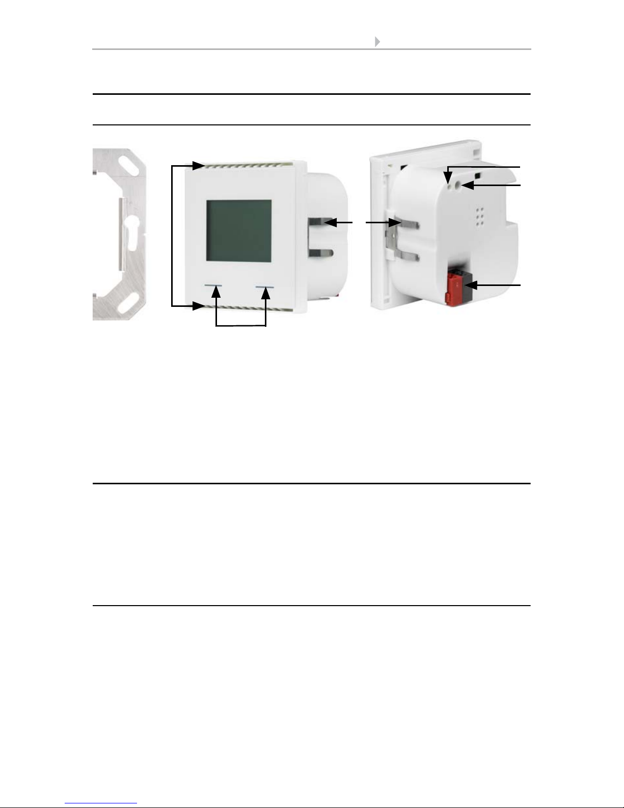
2.3. Composition ............................................................................................................. 8
2.3.1. Housing .......................................................................................................... 8
2.4. Assembly of the sensor ........................................................................................... 8
2.5. Notes on mounting and commissioning ................................................................ 8
3. Display and operation at the device .................................................... 9
3.1. Mode display and manual temperature controller ................................................ 9
3.2. Change ambient temperature with the buttons .................................................. 10
4. Transfer protocol ............................................................................... 12
4.1. List of all communications objects ....................................................................... 12
5. Parameter setting .............................................................................. 23
5.1. Behaviour on power failure/ restoration of power .............................................. 23
5.2. General settings ..................................................................................................... 23
5.3. Temperature value ................................................................................................. 23
5.4. Temperature threshold values .............................................................................. 24
5.4.1. Threshold value 1, 2, 3 ............................................................................... 24
5.4.1.1. Threshold value ............................................................................ 24
5.4.1.2. Switching output .......................................................................... 25
5.4.1.3. Block .............................................................................................. 26
5.5. Temperature PI control .......................................................................................... 26
5.5.0.1. General control ............................................................................. 26
5.5.1. General set point values ............................................................................. 28
5.5.1.1. Set point Comfort ......................................................................... 29
5.5.1.2. Standby setpoint ........................................................................... 30
5.5.1.3. Eco setpoint ................................................................................... 30
5.5.1.4. Setpoint values for frost/heat protection (building protection) 31
5.5.1.5. General control variables ............................................................. 31
5.5.2. Heating control level 1/2 ............................................................................. 32
5.5.3. Cooling control level 1/2 ............................................................................. 34
5.6. Humidity measurement ......................................................................................... 36
5.7. Humidity threshold values .................................................................................... 36
5.7.1. Threshold value 1, 2 ................................................................................... 37
5.7.1.1. Threshold value ............................................................................ 37
5.7.1.2. Switching output .......................................................................... 38
5.7.1.3. Block .............................................................................................. 38
5.8. Humidity PI control ................................................................................................ 39

2 Content
Elsner Elektronik GmbH • Sohlengrund 16 • 75395 Ostelsheim • Germany
Sensor KNX AQS/TH-UP Touch • from ETS programme version 1.0
Status: 23.10.2018 • Technical changes and errors excepted.
5.8.0.1. General control ............................................................................. 39
5.8.0.2. Controller setpoint ........................................................................ 40
5.8.0.3. Dehumidification and/or humidification ..................................... 41
5.9. Dewpoint measurement ........................................................................................ 42
5.9.1. Cooling medium temp. monitoring ........................................................... 42
5.9.1.1. Threshold value ............................................................................ 42
5.9.1.2. Switching output .......................................................................... 43
5.9.1.3. Blocking ......................................................................................... 43
5.10.Absolute humidity ................................................................................................. 44
5.11.Comfort field .......................................................................................................... 45
5.12.CO2parameter settings ......................................................................................... 45
5.13.CO2 threshold values ............................................................................................ 46
5.13.1. Threshold value 1, 2, 3, 4 ........................................................................... 46
5.13.1.1.Threshold value ............................................................................ 46
5.13.1.2.Switching output .......................................................................... 47
5.13.1.3.Block .............................................................................................. 48
5.14.CO2 PI-control ........................................................................................................ 49
5.14.0.1.General control ............................................................................. 49
5.14.0.2.Controller setpoint ........................................................................ 49
5.14.0.3.Ventilation control ........................................................................ 50
5.15.Variable comparator .............................................................................................. 51
5.15.1. Control variable comparator 1/2 ................................................................ 51
5.16.Logic ........................................................................................................................ 52
5.16.0.1.AND logic ....................................................................................... 52
5.16.0.2.OR logic ......................................................................................... 52
5.16.1. AND logic 1-4 and OR logic outputs 1-4 ................................................... 52
5.16.1.1.Block .............................................................................................. 54
5.16.2. Connection inputs of the AND logic .......................................................... 54
5.16.3. Connection inputs of the OR logic ............................................................. 56
5.17.Display .................................................................................................................... 56
5.18.Pushbutton ............................................................................................................. 58
5.18.1. Pushbutton for temperature control ......................................................... 59
5.18.2. Pushbutton interface .................................................................................. 59

3 Clarification of signs
This manual is amended periodically and will be brought into line with new software
releases. The change status (software version and date) can be found in the contents footer.
If you have a device with a later software version, please check
www.elsner-elektronik.de in the menu area "Service" to find out whether a more up-to-
date version of the manual is available.
Clarification of signs used in this manual
Installation, inspection, commissioning and troubleshooting of the device
must only be carried out by a competent electrician.
Safety advice.
Safety advice for working on electrical connections, components,
etc.
DANGER! ... indicates an immediately hazardous situation which will lead to
death or severe injuries if it is not avoided.
WARNING! ... indicates a potentially hazardous situation which may lead to
death or severe injuries if it is not avoided.
CAUTION! ... indicates a potentially hazardous situation which may lead to
trivial or minor injuries if it is not avoided.
ATTENTION! ... indicates a situation which may lead to damage to property if it is
not avoided.
ETS In the ETS tables, the parameter default settings are marked by
underlining.
Table of contents
Other KNX Accessories manuals