Kobastar K1 User manual

1
KOBASTAR K1 USER MANUAL

2
TABLE OF CONTENT
1.0 BRIEF INTRODUCTION………………..…………………………………………..………………...……………………………….3
1.1 TECHNICAL PARAMETERS……………….………………….….…………………………………3
2.0 INSTALLATION………….…….………………………………………………………….…………….………..………………………3
2.1 INDICATOR INTERFACE………….………………..…………………………………………..……3
2.1.1 K1 BACKSIDE……..…..…………………………………………………………..…………3
2.1.2 Loadcell with connection…..……..………………….…………………………….…4
2.1.3 Serial Communication Wire Connection..…….………………………………..4
3.0 OPERATION………………..…………………………………………………………………………………………………………….4
3.1 AUTO ZERO WHEN TURN ON AND OFF…………………………………………………………4
3.2 MANUALLY ZERO...……………………………………………………………………………………….4
3.3 TARE………….………………………………………………………………………………………………….5
3.4 OPERATION FOR TOTAL DISPLAY AND FUNCTION……………………....……………..…5
5.0 CALIBRATION.……………………………………..……………………………………………………………………………………6
6.0 OTHER PARAMETER SETTING AND FUNCTION……………..……….…………………..……………………………..6
7.0 ERROR WARNING.…………………………………………………………………………………………………………………….9

3
1.0 BRIEF INTRODUCTION
Weighing Indicator XK3118T1 adopts high anti-jamming Single-chip microprocessor and high
precision A/D conversion technology. It is with stainless steel frame (XK3118T1B is with plastic frame)
and widely applied in electronic pplatform scale, electronic floor scale and other static weighing
systems that equipped with 1-6pcs load cells. AC/DC are both available fort his indicator.
1.1 TECHNICAL PARAMETERS
Accuracy class: III, n=3000
A/D conversion method 20bit
Input sensitivity > 1.5uV/e
Load cell excitation: DC 5V, connect with 1-6 pcs loadcells with 350 ohm each
Loadcell connection mode: 6 wire (long wire auto compensation)
Division: 1/2/5/10/20/50 optional
Display: 6 bits LED, 10 indicating signs;
Specialized adapter power supply: AC 110-220V, 50Hz-60Hz(special adapter)
6V/4AH built-in maintaince free Lead-Acid battery
Working temperature 0-+40 °C , Humidity=85%(RH)
Storage temperature: -20~+60°C, Humidity=95%(RH)
2.0 INSTALLATION
2.1 INDICATOR INTERFACE
2.2 K1 BACK SIDE

4
2.1.2 Loadcell with Connection
Specification
① - Excitation
② - Feedback
⑥ + Excitation
⑦ + Feedback
⑧ - Signal
⑨ + Signal
⑤ Shield
! Connection between load cell and indicator must be reliable, shield wire must be connected
to ground reliably. Connection or disconnection are not allowed when the indicator is on, which
may damage the indicator or load cells.
! Static protection must be properly adopted as the load cell and indicator are all static sensitive
equipments. Welding or other strong electricity operation should be strictly forbidden. During
thunderstorm season, proper lightening protection should be tanken care of to protect the load
cells and indicators from damaging by lightening and to ensure the personal safety and the safely
running of the weighing and related equipments.
2.1.3 Serial Port Cummunication Wire Connection
Serial Port Chart

5
3.0 OPERASYON
3.1 CİHAZ AÇMA/KAPATMA VE OTOMATİK SIFIRLAMA
The indicator power can be controlled by the on-off key on the front faceplate . The indicator
will perform self-check after turned on. If the scale was found departure from the calibrate zero
however still within the range of turn on auto zero then the indicator will display “0” and the in
dicator light for “zero digit” will be on. If the scale was found departure from the calibrate zero and
out of the range of turn on auto zero then the indicator will display the current read
If the range setting of the turn on zero is”- -“ wihch means zero of last turn off, then zero
operation will not be carried on and the zero of last turn off will be automatically readin and the
current weight will be displayed.
3.2 ELLE SIFIRLAMA
Indıcator will back to zero when pressing “ZERO” key if the gross weight is within the range
of manually zero and stable. Manually zero is not valid under the “NET” displaying mode;
3.3 DARA ALMA
TARE operation can be carried out if both gross weight and net weight are above zero and
stable.
The indicator will display ”0” after pressing the “TARE” key. The tared weight is current gross
weight. And the indicator will enter “NET” displaying mode and the “NET” indicator lights will be on;
The indicator will exit “NET” displaying mode after pressing “TARE” when the gross weight is
“0” and under “NET” displaying mode
3.4 TOPLAM ALMA, TOPLAMI GÖSTERME VE TOPLAMI TEMİZLEME
1. In case, the net weight is bigger than the minimum measurable value (5 divison) and stable,
When pressing “TOTAL”, the current net weight will be added and the “TOTAL” indicator light will be
on and total value will be displayed , which will be changed to adding times [n ***]
After 3 seconds and exit the total displaying status after another 3 seconds. Next operation will be
only valid when the net weight is smaller than the minimum measurable value.
2. If keep pressing “TOTAL” until buzzer alarms under the weighing status “FUNCTION” and “TOTAL”
lights will be on and you can check the total value by pressing “” to see the adding times and again
“” to exit.
3. If you press ““ after keep pressing “ TOTAL” and enter the total displaying status there will be an
notice [CLRAr-] which means to clear the total value or not. Press ““ to clear and “FUNCTION” to
exit and keep the value.

6
OPERATION DIAGRAM
4.0 CALIBRATION
After self checking of turn on, it will enter normal weighing display, warm up for 15-30
minutes, open the calibration cover in the back side of the indicator; touch the calibration switch to
enter calibration status, the detailed steps as below:
Steps Operation Display Specification
【 CAL 】 Means enter calibration status, press “” button to
next step;
1 “”to select
division
“”to confirm
【E 01】 Set division:1、2、5、10、20、50
2 “”to select
decimal point
“”to confirm
【dC 0】 Set decimal point position: press up and down arrow
to switch decimal point0、0.0、0.00、0.000。
3 Set full capacity 【F030.00】 Set Full Capacity:
Press ”” the flash digit will move towards right
Press ”” to increase the number of flash digit
Press “” to confirm and enter next step.
For example: 3000
4 After stable, press to
confirm
【noLoAd】 Zero calibration: Make sure indicator under no-load
status, press “”after date stable to confirm Zero
5 Input the weight of
loading weights
【AdLoAd】
After display
for 2 seconds,
auto switch to
load input
【003.000】
Linearity Calibration:
Add the weights to the scale, input the value of the
weights in indicator, it is better to close to the full
capacity. Operation is same as full capacity setting.
5 seconds after the stable indicator light on
Press “” to confirm and finish the calibration
6 Return back to
weighing status
【 End 】
【 3.000】
After calibration, 2 second after display “End”, the
current weight will be displayed immediately.
★ “ Fn” tuşu ile kalibrasyonu tamamlamadan çıkabilirsiniz.
Keep Pressing
“Total”
Display Total
Value
Press ”” to see
the adding times
Press ”” to exit
Press “” to
celar total value
Press “” to
confirm clear
Press “FUNCTION”
to cancel

7
5.0 OTHER PARAMETER SETTING AND FUNCTION
Steps
Operations Display Note
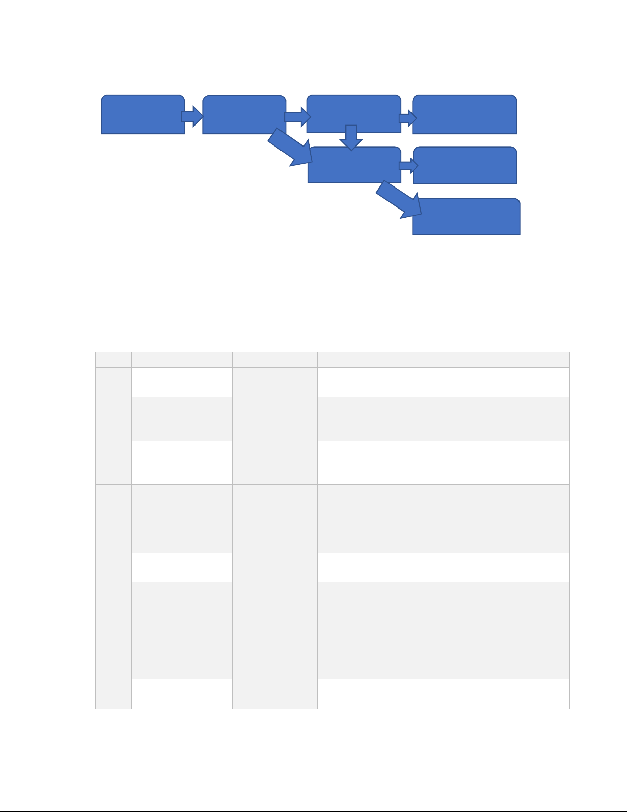
1 Keep Pressing
“FUNCTION” to Enter
“ “ to Switch
“ “ to Confirm
[FN **] “Functıon” Setting:
[ Lb]: One key switch (kg/lb), (Not available under net weighing status)
[ANL]: Animal Scale, One key total and lock display.
[ --]
2
“ “ to Switch
“ “ to Confirm
[PS **] Power Save Setting:
[oFF]: Power save mode off
[oN]: Open power save mode. The power save mode will be entered 5
minutes after weight stable. The indicator will only display date circultly
in last digit
[onP]: Enchanced power save mode which will automatically turn off
the indicator after 5 minutes power save mode.
3 “ “ to Switch
“ “ to Confirm
[ br****] Baud Rate Setting: 600~9600bps Optional
4 “ “ to Switch
“ “ to Confirm
[Co *] Comunicate Mode Setting: 1~6 Optional, Detailed format followed
5
High Setting
[H*****] High Setting:
Press “ “ the flash digit will move towards right
Press “ “ to increase the number of flash digit
Press “ “ to confirm and enter next step such as 2000
6
Low Setting
[ L*****] Low Setting:
Press ““ the flash digit will move towards right
Press “ “ to increase the number of flash digit
Press “ “ to confirm and enter next step such as 1000
If weight is higher than High setting the “HI” light on left side of the
indicator will be on
If weight is lower than low setting the “LO” light on left side of the
indicator will be on
If the weight is between High and Low setting the the “OK” light will be
on
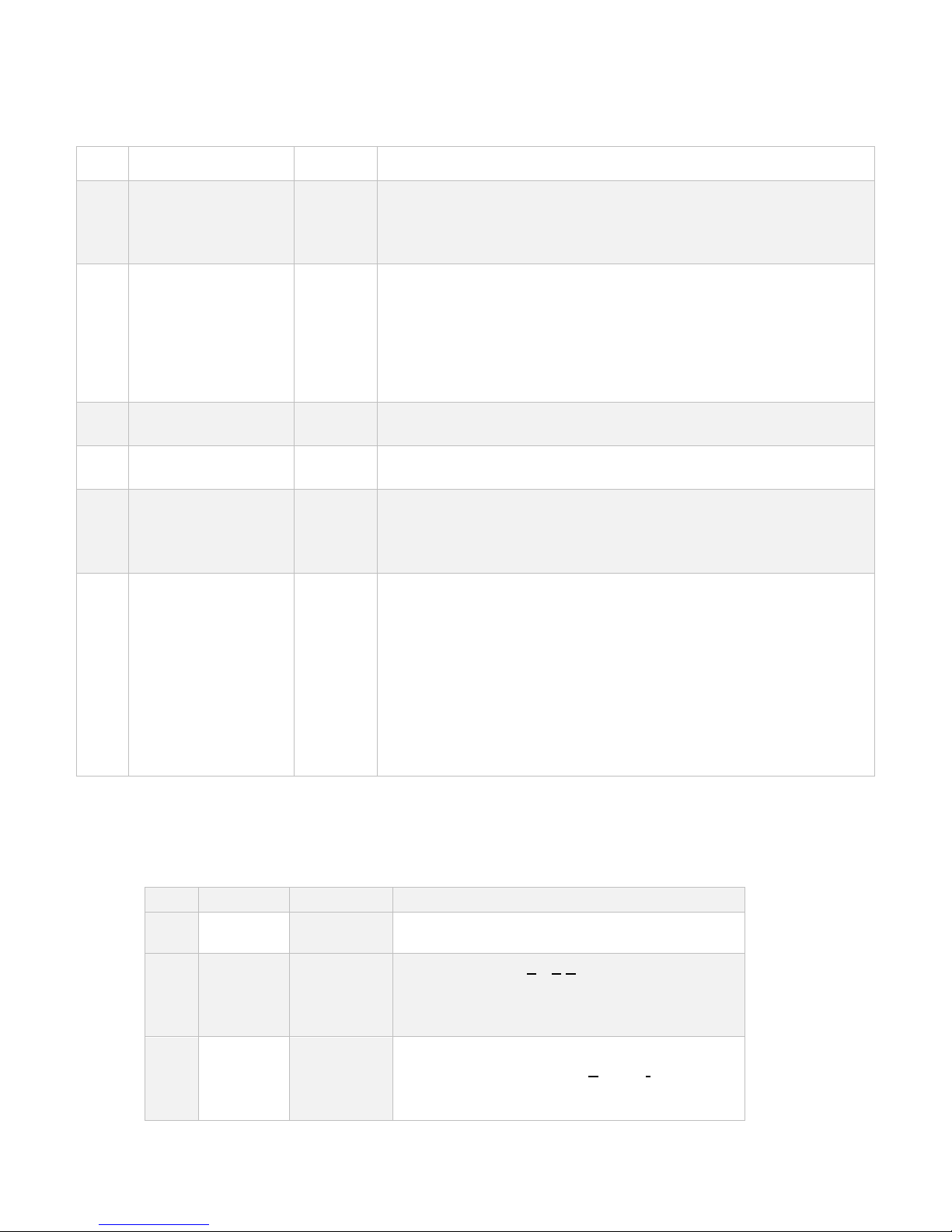
After enter calibration and display 【CAL】, press “” button, indicator displays 【Zero】, then
press “” enter to other parameter calibration setting, the detailed steps as below:
Step Operation Display Specification
【Zero】 Means enter other parameter calibration status,
press“↙”button to next step;
1
“” to
switch
“”to
confirm
【Zot *.*】
Zero trace range(Zero Trace):0~4d,
When the object weight is within the set division,
the indicator will return back to zero
automatically
2
“”to
switch
“”to
confirm
【nt **】 Manual set zero range(Manual Set Zero):0
,2,4,10,20,100 % of full capacity;

8
3
“”to
switch
“”to
confirm
【At **】
Power on auto set zero range(Auto Set Zero)
:
0,2,4,10,20,100 % of full capacity;
4
“”to
switch
“”to
confirm
【FL ***】
Filter set(Filter):
【Stb】:stable algorithm(Stable);
【SEn】:sensitive algorithm(Sensitive);
【 3】:strong vibration resistance
algorithm;
【 4】:high accuracy algorithm;
COMMUNICATION MODE FORMAT
Serial Number of each frame Note
1
8
Reversely send the Net Weight date. For example if the net
weight is 23.45 kg.
ASCII code 54.3200 will be sent. And if the net weight is -
23.45kg, ASCII code 54.320- will be sent
2 8 Reversely send Gross Weight date. The format is same as
serial 1
3
14
Positively send the Net Weight date with unit. For example if
the netweight is 23.45kg, ASCII code = 0023.45 (kg) will be
sent.
End with Hex number 0D,0A
4 14 Positively send the Net weight date with unit. The format is
same as serial 3
5
No
Confirm
Order Response Mode: Order mode 02 “Order” 03 (Hex)
There are 5 pices order, ASCII code ‘A’~’E’. Take gross weight
23.45 kg, net weight 13.45kg and tare 10.00 kg for example
‘A’: Read gross weight, indicator back: GW:0023.45(kg)
‘B’: Read net weight, indicator back: NW:0013.45(kg)
‘C’: Read tare, indicator back: TW:0010.00(kg)
‘D’: Manually zero, indicator back: ‘D’
‘E’: Tare operation, indicator back: ‘E’
All order back add 02 at the beginning and 03 at the end (HEX)
6 Net and total weight can be automatically output in Total
operation and the date can be printed if connected with serial
printer.

9
6.0 ERROR NOTICE
Display Note
Err 01 Exceed the Zero Range
Err 02 Not Meet the Requirement of Total
Err 03 Weight Overloaded
Err 04 Weight not stable during Calibration
Err 05 Load Calibratin Error. Too low load or
Calibration code too small or AD everse
Err 09 Data read verify Error, Data Memory Damaged
Err 10 Boot verift Error, SCM damaged
K1 INBOX
No Name PCS
1 Indicator 1
2 Adapter 1
3 Communication Plug (9 Pin) 1
4 Manual 1
5 Certificate 1

10
www.kobastar.com
KOBASTAR CENTER OFFICE
Adress : Fevzi Çakmak Mah. Ayyıldız Cad. No:16/F Karatay/Konya / TURKEY
Phone : +90 332 249 38 15
+90 332 249 38 16
Fax :+90 332 249 38 17
E-mail : bilgi@kobastarloadcell.com
This manual suits for next models
1
Table of contents
Popular Accessories manuals by other brands

Burnham
Burnham Aquastat IQ Option Card instruction sheet

Emerson
Emerson Rosemount 225 Reference manual

Moeller
Moeller Xcomfort CSEZ-01/11 Assembly instructions

Steren
Steren ALA-036 user manual

Clearaudio
Clearaudio TT1 MI user manual

Thermo Scientific
Thermo Scientific AquaSensors AnalogPlus 1.0 user guide