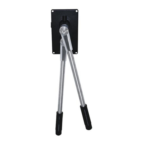
Kobelt 6527 Instruction Manual

6527 Electronic Actuator
Owner’s Operation, Installation &
Maintenance Manual

6527 Actuator Kobelt Manufacturing Co. Ltd.
Rev A MNL-6527.docx Page 1 of 32
NOTES:
RECORD DATA BEFORE INSTALLATION FOR FUTURE REFERENCE
Model #:
Serial #:
Date of Purchase:
Date of Installation:

6527 Actuator Kobelt Manufacturing Co. Ltd.
Rev A MNL-6527.docx Page 2 of 32
TABLE OF CONTENTS
1Introduction .......................................................................................................... 3
1.1 Contact .......................................................................................................................3
1.2 Safety..........................................................................................................................3
2Product Description ............................................................................................... 5
2.1 Overview.....................................................................................................................5
2.2 Technical Data ............................................................................................................6
2.3 Model Configuration Key ...........................................................................................6
3Installation............................................................................................................ 7
3.1 Mechanical .................................................................................................................7
3.2 Control Cable..............................................................................................................7
3.3 Electrical ...................................................................................................................11
4Commissioning .................................................................................................... 16
4.1 Electrical Check.........................................................................................................16
4.2 Calibration and Adjustment .....................................................................................16
4.3 Functional Test .........................................................................................................19
5Operation............................................................................................................ 19
5.1 Manual Override ......................................................................................................19
6Maintenance ....................................................................................................... 20
6.1 Preventative Maintenance.......................................................................................20
6.2 Inspection.................................................................................................................20
6.3 Calibration ................................................................................................................20
6.4 Potentiometer Connection.......................................................................................21
6.5 Lubrication................................................................................................................22
6.6 Recommended Spare Parts......................................................................................22
7Troubleshooting .................................................................................................. 23
8Warranty............................................................................................................. 24
9Appendix A: Installation Dimensions .................................................................... 25
10 Appendix B: Parts List .......................................................................................... 26

6527 Actuator Kobelt Manufacturing Co. Ltd.
Rev A MNL-6527.docx Page 3 of 32
1INTRODUCTION
1.1 CONTACT
Kobelt Manufacturing Co. Ltd.
8238 129th Street
Surrey, British Columbia
Canada, V3W 0A6
Sales Tel:
Fax:
Email:
Website:
This document is intended to clearly present comprehensive product data and provide
technical information to assist the end user in design applications. Kobelt reserves the right,
without notice, to change the design, or construction, of any products and to discontinue or
limit distribution of any products. Kobelt also reserves the right to change, or update,
without notice, any technical information contained within this document.
Kobelt recommends that customers visit our website to check for updates to this Manual.
Once a product has been selected for use, it should be tested by the user to ensure proper
function in all possible applications. For further instructions, please contact our distributors
or visit our website.
1.2 SAFETY
1.2.1 Safety Alerts
Throughout this manual, the following symbols, and their accompanying explanation, are
used to alert the user to special instructions concerning a service or operation that may be
hazardous if performed incorrectly or carelessly. The associated risk levels are stated below.
This symbol indicates an imminently hazardous situation which, if
not avoided, will result in death or serious injury.
This symbol indicates a potentially hazardous situation which, if not
avoided, could result in death or serious injury.
This symbol indicates a hazardous situation, which if not avoided,
could result in minor or moderate injury.
This symbol informs the reader of events not related to personal
injury but which there is a risk of damage to property or equipment.
This symbol informs the reader of safety-related instructions or
procedures.

6527 Actuator Kobelt Manufacturing Co. Ltd.
Rev A MNL-6527.docx Page 4 of 32
1.2.2 Notice to Installer
Disregarding the following safety measures can result in an accident, causing severe injury to
personnel and damage to material assets.
•Only use the product as directed in this manual.
•Never put the product into service if there is evidence of visible damage.
•Never put the product into service before fully completing installation and
commissioning.
•Do not carry out any modifications to the product.
•Only use authentic Kobelt spare parts.
•Observe all local regulations, directives and laws during the installation of this product.
•All installation, commissioning, and maintenance work must only be conducted by
qualified personnel. (For the purpose of this manual, qualified personnel are persons
who are familiar with the assembly, installation, commissioning, and operation of the
product and who have the qualifications necessary for their occupation.)
•Observe all specifications in this manual. If these guidelines are not followed and
damage occurs, the warranty will be voided.
1.2.3 Product Hazards
Disconnect Power:
Turn off power at distribution panel before beginning installation to
protect installer from electrical hazards.
Voltage and Current Compatibility:
Confirm that the power source is compatible with the maximum
voltage and current ratings of is product variant. Failure to do so
could result in damage or fire.
Equipment Starts Automatically:
Vessel propulsion may activate suddenly while servicing this
product, causing bodily harm. Ensure that all power sources are
locked out prior to performing work.
Pinch Points:
The 6527 actuator contains pinch points, which can cause bodily
harm. Ensure that hands and fingers remain clear of the pinch
points when performing work.

6527 Actuator Kobelt Manufacturing Co. Ltd.
Rev A MNL-6527.docx Page 5 of 32
2PRODUCT DESCRIPTION
2.1 OVERVIEW
The Kobelt 6527 actuator is an electro-mechanical actuator that converts rotary motion from
a DC motor to produce linear motion on a push/pull cable via the output lever. The 6527-S
version has onboard electronics to control the motion and is connected to the Mighty
Mariner propulsion control system via a CANbus interface. The onboard electronics receives
commands from the control heads and positions its output lever to control engine throttle,
clutch engagement, or trolling speed.
The basic Model 6527 comes with manual override and one trim pot per side for stroke
adjustment. The actuator does not have an internal resilient link. Hence the stroke must be
precisely adjusted to suit the device being controlled.
Figure 1: Actuator Overview

6527 Actuator Kobelt Manufacturing Co. Ltd.
Rev A MNL-6527.docx Page 6 of 32
2.2 TECHNICAL DATA
Table 1: 6527-S Technical Data
MODEL
6527
KOBELT PART #
6527-S
6527
System compatibility
Mighty Mariner
Basic version
Output
No load
Cont.2
Rated
Stall
Torque
0 [0]
82 [9.3]
180 [20.3]
500 [56.5]
(in-lbs) [Nm]
Force
0 [0]
59 [262]
130 [579]
362 [1611]
(lbs) [N]
Speed
83
67
53
0
(deg/sec)
Current
.3
1.8
3.4
8.6
(A)
Max ON time1
54
29
11
(secs)
Duty1
100%
25%
13%
5%
(% on)
Stroke
75o
Supply voltage
24 (+/-25%) VDC
Terminals
22-16 AWG, screw clamp
EMC emissions
to IEC 60945
EMC immunity
to IEC 60945
Environmental category
ENV2 / Protected
Operating temperature
41°F … 131°F [5°C … 55°C]
Vibration resistance
0.7 g
Product weight
28.7 lbs [13.0 kg]
Finish
Uncoated Bronze
Notes:
1. Specified at maximum ambient temperature (55oC)
2. At 25oC ambient temperature
2.3 MODEL CONFIGURATION KEY
The 6527 actuator is manufactured in two versions:
6527-S Mighty Mariner version with onboard electronics
6527 Basic version with positioning motors and feedback potentiometers only
Please ensure you refer to the correct sections of this manual for technical assistance

6527 Actuator Kobelt Manufacturing Co. Ltd.
Rev A MNL-6527.docx Page 7 of 32
3INSTALLATION
3.1 MECHANICAL
The location of the 6527 Electronic Actuator must satisfy the following conditions:
•Vibrations not to exceed rated vibration resistance (see table 1)
•Ambient temperatures not to exceed rated temperature (see table 1)
•Do not install in areas exposed to moisture
•Do not install near high-power devices
•Ensure that the mounting surface flat within .01” [.25 mm]
When installing the unit;
1. Set the unit on the mounting surface and orient to desired operating position.
2. Probe under the feet with a feeler gauge to determine shimming requirement.
3. Insert the shims determined from step 6. Use ANSI shims that straddle the
mounting bolts.
4. Insert 1/4in [6 mm] bolts. It is recommended to use a thread locking product such
as Loctite® to ensure a vibration resistant and secure joint.
5. Tighten the mounting bolts to 64 in-lbs [7.2 Nm]
Mounting:
Failure to comply with the mounting instructions above may
result in failure of the actuator and loss of control over the
engine.
3.2 CONTROL CABLE
3.2.1 Hardware
The 6527 actuator can be used with either 30 series or 40 series control cable. Kobelt
Manufacturing does not recommend solid core cables if bends are present in the cable
routing. A solid core cable would consist of a single wire that is too stiff. Multi-stranded
cores are more flexible and therefore generates less friction during operation.
The cable ends must also be able to
articulate approximately 8 degrees in
either direction.

6527 Actuator Kobelt Manufacturing Co. Ltd.
Rev A MNL-6527.docx Page 8 of 32
Accurate Positioning:
For applications that require accurate positioning, a tie rod with
rod ends is recommended over a push/pull cable.
For terminating the cables Kobelt recommends a ball rod end. Rod ends are self-aligning and
therefore minimize friction and binding.
When installing hardware to the cable end, do not twist the core. If required, use a pair of
pliers to hold the cable core from turning while installing the terminating hardware. When
gripping the cable end, apply the pliers immediately under the threads and take care not to
score the cable rod. A scored cable rod will damage the cable seal allowing moisture and dirt
to enter the casing.
To install the 6527 actuator, the appropriate connection kit must be purchased. Consult the
table below for the correct kit:
Table 2: Connection Kits
Use Case
Kit Number
30 series cable
6527-0901
40 series cable
6527-0902
3.2.2 Cable Routing
Measure the cable along the path it will take from where the
cable hubs will be anchored at each end. Follow the actual
cable path as closely as possible, allowing for the largest
practical bend radii.
Do not force the cable into tighter bends than what is listed in
the table below:
Optimum Life Bend Radii
Cable Size
Min Bend Radius
30 series
3 inches1[76 mm]
40 series
4 inches [127 mm]
Solid core
6 inches [152 mm]
It is important to securely anchor the cable hubs. Any free play in the cable clamp or
mounting bracket will result in lost motion.

6527 Actuator Kobelt Manufacturing Co. Ltd.
Rev A MNL-6527.docx Page 9 of 32
When securing the cable with clamps near
bends, position two clamps at the ends of
the bend rather than one in the middle.
When installing a push-pull cable, do not kink
the cable since this will permanently damage
the core and casing, rendering the cable stiff
and inoperable. Even minor kinks will result
in premature failure.
Avoid routing the cable near sources of heat, such as exhaust pipes.
3.2.3 Cable Connection
The 6527 actuator has a lever
mechanism for actuating the clutch
and the throttle. Consult the
figure at left to select the correct
function.
Select the appropriate pin position
to provide the required stroke and
force. Consult the Table below:
Table 3: Actuator Output
The clutch valve mechanism on
most marine transmissions requires
approximately 2¾” [70 mm] to 3” [76 mm] of travel. Consequently, the cable must be
attached at pin position 4 of the output lever.
Pin
Stroke
in [mm]
Force
lbs [N]
1
1.67 [42]
130 [580]
2
2.13 [54]
103 [456]
3
2.59 [66]
85 [376]
4
3.05 [77]
72 [320]
5
3.51 [89]
62 [278]
6
4.05 [103]
55 [246]
Figure 3: Cable Pin Positions
Figure 2: Lever Assignment

6527 Actuator Kobelt Manufacturing Co. Ltd.
Rev A MNL-6527.docx Page 10 of 32
In some marine applications with twin engines, both engines are turning in the same direction
and therefore one gear box is running in the reverse to drive the propeller ahead. In this
particular installation the actuators must rotate in opposite directions to provide the proper
push and pull mode for either gear.
To correctly install the control cables, follow the steps below:
1. Secure the cables to the support bracket with the appropriate cable clamps.
2. Move the output lever to the extreme forward position.
3. Ensure that the cable end extends slightly past the desired pin position.
4. Move the output lever to the extreme aft position.
5. Ensure that the cable end, when in push mode, extends beyond the same desired
pin position.
6. If the cable end points from one extreme to the other are unequal, then the cable
end fitting must be threaded out or in to correct balance the range of motion.
7. After the proper position is found, the cable end is attached to the output lever and
the jam nut tightened.
8. The final step is to test that the actuator goes from neutral to both forward and then
reverse gear engaged positions without bottoming.
3.2.4 Actuator End Connection
When connecting the actuating end of the
cable to the throttle or clutch lever, install
the cable so that the greatest loads are in
tension (pulling) rather than compression
(pushing), if possible.
Where the cable is connected to a
lever, the cable must be mounted so
that it lies on a plane (A) midway on
the arc (B) described by the
movement of the connection point
on the lever (C).
When connecting the actuating end of the cable to
a spool valve such as the Kobelt 4605 servo
cylinder, maximum cable life and efficiency is
achieved when the cable is aligned with the lever
in two planes. Reference the figure at right:

6527 Actuator Kobelt Manufacturing Co. Ltd.
Rev A MNL-6527.docx Page 11 of 32
3.3 ELECTRICAL
3.3.1 Mighty Mariner System
The 6527-S actuator is equipped with three cable glands with which to make the electrical
connections. Use 0.20 inch [5 mm] to 0.47 inch [12 mm] OD cable with 18 AWG conductors
for external connections to the engine controller. The cable must be twisted pair and
shielded to protect signal integrity. Use ferrules on the cable ends for all wire connections.
Plug connectors are supplied on the board inside of the electrical enclosure. They can be
accessed by removing the enclosure cover. Use these connectors for making the connections
to the actuator.
Connectors P1 and P2 are mandatory and required for operation of the 6527-S Electronic
Actuator. Connectors P3, P4, and P5 are optional depending on system configuration.
Connectors P6 and P7 are factory-installed and should not be modified.
Up to eight control heads and actuators can be connected in a ‘daisy chain’ fashion to either
the P2 or P3 connector for making the communication connections. The last device, whether
an actuator or control head must have a 120 ohm resistor installed between the data
terminals (pins 3 & 4).
Figure 4: Connector Locations
Table 4: Power Input Connector
P1
POWER INPUT
Pin #
Signal
Conductor
Function
1
VDC+
RED
Main Power Input
2
COM
BLK
Main Ground

6527 Actuator Kobelt Manufacturing Co. Ltd.
Rev A MNL-6527.docx Page 12 of 32
Table 5: Primary COM/CPU Port Connector
P2
COM/CPU INPUT
Pin #
Signal
Conductor
Function
1
VDC+
WHT 2
Bus supply
2
COM
BLK 2
Bus common
3
DATA+
WHT 1
Bus data -H
4
DATA-
BLK 1
Bus data - L
5
Shield
SHIELD
Shield
Table 6: Secondary COM/CPU Port Connector
P3
COM/CPU INPUT
Pin #
Signal
Conductor
Function
1
VDC+
WHT 2
Bus supply
2
COM
BLK 2
Bus common
3
DATA+
WHT 1
Bus data -H
4
DATA-
BLK 1
Bus data - L
5
Shield
SHIELD
Shield
3.3.1.1 Synchronizer/Tachometer Connection
The Synchronizer sensor is realized with a three-wire proximity switch connected directly to
the 6527-S as shown in Error! Reference source not found.the figure below.
Figure 5: Synchronizer Pickup Wiring Diagram
Table 7: Tachometer Port Connector
P4
SYNCHRO PORT
Pin #
Signal
Conductor
Function
1
VDC+
BRN
Sensor Power
2
SYNCH PULSE
BLK
Sensor Signal
3
COM
BLU
Sensor Common
Disconnect Power:
Turn off power at the distribution panel before beginning
installation or removing the cover.
The last control head must have a 120 ohm resistor between
terminals 3 & 4 or network communication will be lost.

6527 Actuator Kobelt Manufacturing Co. Ltd.
Rev A MNL-6527.docx Page 13 of 32
3.3.1.2 Shaft Brake/Neutral Safety Connection
The Shaft Brake/Neutral Safety Output is a set of normally open contacts that close when the
Clutch is in the neutral position. Configuring the output for Shaft Brake or Neutral Safety is
done using external relays and protection diodes.
The Neutral Safety Switch configuration is seen in Figure 6. The relay is interlocked to Clutch
Neutral Position, the engine can only be started when the system is powered and the Control
Head levers are in neutral position.
Figure 6: Neutral Safety Switch Wiring Diagram
Table 8: Neutral Safety Port Connector
P5
NEUTRAL SAFETY PORT
Pin #
Signal
Conductor
Function
1
N/O
RED
Relay Contact, N/O
2
COM
WHT
Relay Contact, Common
Note that the Neutral Safety relay is also used to control the shaft brakes when present. The
Shaft Brake configuration is seen in Figure 7. As the Forward or Reverse Clutch is activated,
the Brake Relay disconnects, and the Brake is deactivated.
Figure 7: Shaft Brake Switch Wiring Diagram

6527 Actuator Kobelt Manufacturing Co. Ltd.
Rev A MNL-6527.docx Page 14 of 32
Relay Current:
Relay contacts must be able to handle starter solenoid current.
Relay is customer supplied.
Protection Diodes:
Protection diodes must be used on all external relays to avoid
damaging the system.
Neutral Safety Switch Bypass:
A bypass for the neutral safety switches must be available to
start the engines if the control system has failed.
Check All Connections:
Improper wiring connections may result in damage to the 6527-S
Electronic Actuator.

6527 Actuator Kobelt Manufacturing Co. Ltd.
Rev A MNL-6527.docx Page 15 of 32
3.3.2 6525 System
The 6527 basic actuator for use with the 6525 system does not have a circuit board and
therefore has a different wiring scheme. Consult the diagram below to connect the actuator
correctly:
Table 9: 6527 Actuator Terminations
Throttle Lever
Terminal #
Signal
Wire
Function
1
Motor
BLK
Motor A common
2
Motor
RED
Motor A power
3
Vref+
BLK
Throttle Pot Positive Reference
4
POTA
GRN
Throttle Pot Wiper Input
5
Vref-
WHT
Throttle Pot Negative Reference
Clutch Lever
1
Motor
BLK
Motor B common
2
Motor
RED
Motor B power
3
Vref+
BLK
Clutch Pot Positive Reference
4
POTB
GRN
Clutch Pot Wiper Input
5
Vref-
WHT
Clutch Pot Negative Reference
Notes:
1. The potentiometers are wired mirror image to synchronize the outputs.
2. Terminals 3 & 5 are internally connected and do not require separate
termination

6527 Actuator Kobelt Manufacturing Co. Ltd.
Rev A MNL-6527.docx Page 16 of 32
4COMMISSIONING
4.1 ELECTRICAL CHECK
Ensure that the cover is installed and secured before powering on
the 6527-S.
•Confirm that the electrical connections to the 6527-S have been made.
•Confirm that a breaker has been installed correctly and is turned ON.
4.2 CALIBRATION AND ADJUSTMENT
These adjustments should only be performed by qualified
personnel, and only while the vessel is at dock.
1. Turn OFF the power to the 6527-S prior to adjusting the trimpots or DIP
switches.
1. Remove the enclosure cover
2. Use a non-conductive flathead screwdriver to adjust the trimpots or DIP
switches.
3. Rotate the trimpots to set the desired system response, adjust the DIP switch
positions to configure the system.
4. Turn ON power.
5. Operate system to verify desired response.
1. Repeat as necessary, until the unit functions as desired.
2. Replace the enclosure cover.
4.2.1 DIP Switches
DIP switch SW1 is used to
assign the actuator, set the
travel direction and adjust
the throttle boost. Locate
the DIP switch on the
board and consult the
timing table below to
make the appropriate
settings.
To reduce the potential for electrical shock and to avoid damaging
the electronics, use a non-conductive screwdriver, or other
equivalent tool, to adjust the trimpots and DIP switches.

6527 Actuator Kobelt Manufacturing Co. Ltd.
Rev A MNL-6527.docx Page 17 of 32
Follow the table below to set the DIP switch correctly:
Table 10: DIP Switch Configuration
SW 1 Function
OFF
POSITION
ON
POSITION
FUNCTION
PORT
ACTUATOR
STBD
ACTUATOR
PORT/STBD ACTUATOR
ASSIGMENT
NORMAL
REVERSE
THROTTLE ACTUATOR
TRAVEL DIRECTION
NORMAL
REVERSE
CLUTCH ACTUATOR
TRAVEL DIRECTION
AUXILIARY
MAIN
SYNCHRONIZER
SEE TIMING
THROTTLE BOOST
SEE TIMING
THROTTLE BOOST
In conventional applications, the throttle actuator rotates in a counterclockwise direction to
increase the engine speed and a clockwise rotation to decrease it. If the opposite movement
is desired, the actuator travel direction must be reversed using DIP switch 2 (See Table 10).
The standard clutch actuator rotates in a clockwise direction for forward and counter
clockwise direction for reverse. The direction can be reversed by setting DIP switch 3 (See
Table 10).
Single Engine Configuration: SW1 must be set to OFF position
(PORT ACTUATOR)
The throttle boost amount and duration is set in one of four possible configurations using the
fifth and sixth switches:
Table 11: Throttle Boost Timing
SW 5
SW 6
THROTTLE BOOST
THROTTLE BOOST TIME
OFF
OFF
0%
0 SECONDS

6527 Actuator Kobelt Manufacturing Co. Ltd.
Rev A MNL-6527.docx Page 18 of 32
ON
OFF
10%
2 SECONDS
OFF
ON
20%
2 SECONDS
ON
ON
20%
3 SECONDS
4.2.2 System Timing Adjustment
Table 12: System Timing
System Timing
POT
FUNCTION
DELAY
INCREASE
DECREASE
RATE
VR 1
THROTTLE DELAY
0-24 SECONDS
CW
CCW
2 TURN/SEC
VR 2
NEUTRAL DELAY
0-24 SECONDS
CW
CCW
2 TURN/SEC
Twin Engine Configuration: Neutral delay and throttle delay
must be set identical for both actuators.
One actuator must be set to PORT and the other to STBD, do not
set both to the same switch position (SW 1).
One actuator must be set to MAIN and the other to AUXILIARY,
do not set both to the same switch position (SW 4).
4.2.3 Stroke Adjustment
The 6527-S actuator is equipped with manual overrides and one trim pot per side to adjust
the stroke. The actuator does not have an internal resilient link. The stroke must, therefore,
be adjusted precisely to suit the device being controlled.
Fine adjustments to the throttle or clutch levers stroke can be made using trimpots on the
actuator (See Figure 1). Trimpot 1 adjusts the throttle lever stroke while trimpot 2 adjusts the
clutch lever stroke.
Set the clutch actuator stroke accurately; otherwise, the throttle
actuator will not respond. The clutch motor must stop running
when the correct stroke is obtained. Re-adjust stroke if motor is
still trying to rotate.
To increase actuator stroke, turn trimpot CCW and vice versa.
Lock trimpot when desired position obtained. Do not adjust
actuator near its max stroke. Adjust the stroke accurately to
prevent the actuator from alarming.

6527 Actuator Kobelt Manufacturing Co. Ltd.
Rev A MNL-6527.docx Page 19 of 32
Table 13: Stroke Trimpot Adjustment
Trimpot Adjustment
Stroke Effect
Decrease actuator stroke.
Increase actuator stroke.
4.3 FUNCTIONAL TEST
After installation, test that the clutches go from neutral to both forward and then reverse gear
engaged positions without the actuator motor tripping on over current.
Also ensure that the full speed range is obtained with full actuator travel.
Ensure that the actuator travel directions are correct, and the time delay settings are
appropriate. Adjust if necessary.
5OPERATION
5.1 MANUAL
OVERRIDE
The 6527 has a provision
to permit manual control
over the actuator
functions should a power
failure or actuator failure
occur. Reference the
diagram at right:
Do not put the vessel into service until the control head has been
tested. The Functional Test should be carried out while the vessel is
still at dock.
Figure 8: Manual Override
Table of contents
Other Kobelt Controllers manuals
Popular Controllers manuals by other brands

Metso
Metso Switchguard SG9000H Installation maintenance and operating instructions

Gardena
Gardena 1273 operating instructions

Extron electronics
Extron electronics PC 101 Setup guide

Envirowise
Envirowise D30 Installer's and owner's manual

NETGEAR
NETGEAR ProSAFE WC7600 installation guide

Gewiss
Gewiss Chorus GW 10 767 manual

JLCooper Electronics
JLCooper Electronics FaderMaster 4/100 user manual

Power Dynamics
Power Dynamics PDVC Series instruction manual

RKC INSTRUMENT
RKC INSTRUMENT PF Series user manual

Mitsubishi Electric
Mitsubishi Electric CR750-Q Series instruction manual

NSI
NSI NCM 508 Operation manual

Unitronics
Unitronics Vision OPLC V570-57-T34 installation guide