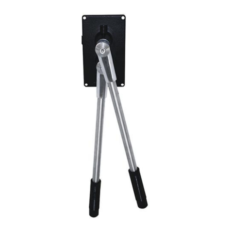
Kobelt 6505 Instruction Manual

Kobelt Manufacturing Co. Ltd.
6505 Electronic Control Head
Owner’s Operation, Installation &
Maintenance Manual

6505 Control Head Kobelt Manufacturing Co. Ltd.
Rev A mnl6505.docx 2 of 18
NOTES:
RECORD DATA BEFORE INSTALLATION FOR FUTURE REFERENCE
Model #:
Serial #:
Date of Purchase:
Date of Installation:

6505 Control Head Kobelt Manufacturing Co. Ltd.
Rev A mnl6505.docx 3 of 18
Table of Contents
1Introduction ..................................................................................................................4
1.1 Contact ...................................................................................................................................... 4
1.2 Safety......................................................................................................................................... 4
1.2.1 Safety Alerts .......................................................................................................................... 4
1.2.2 Notice to Installer.................................................................................................................. 4
1.2.3 Product Hazards .................................................................................................................... 5
2Product Description .......................................................................................................6
2.1 Overview.................................................................................................................................... 6
2.2 Technical Data ........................................................................................................................... 7
2.3 Model Configuration Key........................................................................................................... 7
3Installation ....................................................................................................................8
3.1 Mechanical ................................................................................................................................ 8
3.2 Electrical .................................................................................................................................... 8
3.3 DIP Switch Settings .................................................................................................................... 9
3.4 Functional Test .......................................................................................................................... 9
4Operation....................................................................................................................10
5Maintenance ...............................................................................................................10
5.1 Preventative Maintenance ...................................................................................................... 10
5.2 Calibration ............................................................................................................................... 10
5.3 Potentiometer Connection ...................................................................................................... 11
5.4 Lubrication............................................................................................................................... 11
5.5 Recommended Spare Parts and Kits........................................................................................ 12
6Warranty.....................................................................................................................13
7Appendix A: Installation Dimensions ............................................................................14
8Appendix B: Parts List ..................................................................................................15
9Appendix C: Installation Cut-out Template....................................................................17

6505 Control Head Kobelt Manufacturing Co. Ltd.
Rev A mnl6505.docx 4 of 18
1INTRODUCTION
1.1 CONTACT
Kobelt Manufacturing Co. Ltd.
8238 129th Street
Surrey, British Columbia
Canada, V3W 0A6
Sales Tel:
Fax:
Email:
Website:
This document is intended to clearly present comprehensive product data and provide technical
information to assist the end user in design applications. Kobelt reserves the right, without notice, to
change the design, or construction, of any products and to discontinue or limit distribution of any
products. Kobelt also reserves the right to change, or update, without notice, any technical information
contained within this document.
Kobelt recommends that customers visit our website to check for updates to this Manual. Once a
product has been selected for use, it should be tested by the user to ensure proper function in all
possible applications. For further instructions, please contact our distributors or visit our website.
1.2 SAFETY
1.2.1 Safety Alerts
Throughout this manual, the following symbols, and their accompanying explanation, are used to alert
the user to special instructions concerning a service or operation that may be hazardous if performed
incorrectly or carelessly. The associated risk levels are stated below.
This symbol indicates an imminently hazardous situation which, if not
avoided, will result in death or serious injury.
This symbol indicates a potentially hazardous situation which, if not
avoided, could result in death or serious injury.
This symbol indicates a hazardous situation, which if not avoided, could
result in minor or moderate injury.
This symbol informs the reader of events not related to personal injury
but which there is a risk of damage to property or equipment.
This symbol informs the reader of safety-related instructions or
procedures.
1.2.2 Notice to Installer
Disregarding the following safety measures can result in an accident causing severe injury to personnel
and damage to material assets.
•Only use the product as directed in this manual.
•Never put the product into service if there is evidence of visible damage.
•Never put the product into service before fully completing installation and commissioning.
•Do not carry out any modifications to the product.

6505 Control Head Kobelt Manufacturing Co. Ltd.
Rev A mnl6505.docx 5 of 18
•Only use authentic Kobelt spare parts.
•Observe all local regulations, directives and laws during the installation of this product.
•All installation, commissioning, and maintenance work must only be conducted by qualified
personnel. (For the purpose of this manual, qualified personnel are persons who are familiar with
the assembly, installation, commissioning, and operation of the product and who have the
qualifications necessary for their occupation.)
•Observe all specifications in this manual. If these guidelines are not followed and damage occurs,
the warranty will be voided.
1.2.3 Product Hazards
Equipment Starts Automatically:
Equipment may activate suddenly while servicing this
product, causing bodily harm. Ensure that all power
sources are locked out prior to performing work.
Pinch Points:
The 6505 control head contains pinch points, which can
cause bodily harm. Ensure that hands and fingers
remain clear of the pinch points when performing work.

6505 Control Head Kobelt Manufacturing Co. Ltd.
Rev A mnl6505.docx 6 of 18
2PRODUCT DESCRIPTION
2.1 OVERVIEW
The Kobelt 6505 compact electronic control head provides a 10-bit digital output, communicated via
CANbus, that is proportional to the handle position. This output is used by Kobelt’s Mighty Mariner
controller to control engine throttle, clutch engagement or propellor pitch. The handle also has three
detent positions; one at TDC plus another two to correspond with clutch activation points in both ahead
and astern. The unit is equipped with a keypad to control Station Select, Station Lock, Throttle Override
and Engine Synchronizer functions.
Figure 1: Control head overview

6505 Control Head Kobelt Manufacturing Co. Ltd.
Rev A mnl6505.docx 7 of 18
2.2 TECHNICAL DATA
Handle Travel:
•Neutral: 0odetented
•Clutch in: +/- 20o detented
•Full travel: +/- 68o
Output CANbus (132 ft [40m] maximum)
Terminals 22-16 AWG, screw clamp type
Ambient Temperature: 14°F…+122°F [-10 °C… + 50°C]
Finish: Polyester powder coat
Textured black
Weight: 6.2 lbs [2.8 kg]
2.3 MODEL CONFIGURATION KEY

6505 Control Head Kobelt Manufacturing Co. Ltd.
Rev A mnl6505.docx 8 of 18
3INSTALLATION
3.1 MECHANICAL
The control head must be mounted on a flat surface, strong and stiff enough to withstand the operating
forces imposed during normal use without excessive flexing. Choose a location that has sufficient room
for the handle to swing to both extreme positions. Use the template at the back of this manual to make
the correct cut-out on the mounting surface.
The control head is equipped with (4) four clearance holes for #10 (M5) screws inserted from
underneath for direct mounting to the dash. Ensure the unit is securely fastened, preferable with an
anaerobic thread locker such as Loctite 243.
3.2 ELECTRICAL
The 6505 control head is equipped with two cable glands with which to make the electrical connections.
Use 0.20 inch [5 mm] to 0.47 inch [12 mm] OD cable with 18 AWG conductors for external connections
to the engine controller. The cable must be twisted pair, shielded to protect signal integrity. Use
ferrules on the cable ends for all wire connections.
Plug connectors are supplied on the board of the control head for making the connections to the circuit
board. No power connections are required as the unit receives power through the network from the
controller. Up to eight control heads can be connected in ‘daisy chain’ fashion to connector P2. The last
control head must have a 120 ohm resistor installed between the data terminals (pins 3 & 4).
Figure 2: 6505 Wire Connections

6505 Control Head Kobelt Manufacturing Co. Ltd.
Rev A mnl6505.docx 9 of 18
Table 1: Connector P2 termination
Pin #
Signal
Conductor
1
+ VDC
WHT 2
2
COM
BLK 2
3
DATA+
WHT 1
4
DATA-
BLK 1
5
SHIELD
SHIELD
The last control head must have a 120 ohm resistor between
terminals 3 & 4 or network communication will be lost.
When connecting the Sonalert buzzer to connector P4, ensure that the positive wire is connected to
terminal 1.
Before completing the wiring, remember to leave enough extra cable length to permit removal of the
control head without disconnection the wiring.
3.3 DIP SWITCH SETTINGS
The network address of each control head is assigned via a four pole DIP switch on the circuit board. Set
the switches as shown in the table below:
Table 2: Control Head Address
Station
Address
DIP Switches
SW1
SW2
SW3
SW4
1
OFF
OFF
OFF
ON
2
ON
OFF
OFF
ON
3
OFF
ON
OFF
ON
4
ON
ON
OFF
ON
5
OFF
OFF
ON
ON
6
ON
OFF
ON
ON
7
OFF
ON
ON
ON
8
ON
ON
ON
ON
Set each control head to a different address number. Ensure that number 1 is assigned to the bridge or
main station as this is the unit that will automatically get control after power up.
3.4 FUNCTIONAL TEST
Upon power up, the main station sonalert will start beeping and the STATION SELECT lamp will blink. If
this is not happening, inspect the wiring. After successful power up, press the STATION SELECT switch to
assume control from the current station.
Once in control, test that the clutches engage and disengage as expected and that the full range of
throttle control is available.
Do not put the equipment into service until the
control head has been tested. The Functional Test
should be carried out while the equipment is safely
secured.

6505 Control Head Kobelt Manufacturing Co. Ltd.
Rev A mnl6505.docx 10 of 18
4OPERATION
The 6505 control head is equipped with four membrane buttons that enable the following functions:
STATION SELECT permits the transfer of engine control to another station. On power-up, station
control automatically is assigned to station 1 (main station).
STATION LOCK allows the operator to lock out the other control stations.
THROTTLE OVERRIDE disables the clutch function so that the engine can be operated to full throttle
without turning the propellors. This feature is useful for engine warm-up or
testing.
To return to the normal operating mode, return the handle positions back to
neutral (TDC) and press the button again.
SYNCHRONIZER Pressing this button enables the propellor speed synchronization feature, which
uses external speed sensors to measure the speed and permit the controller to
match the engine speeds. The operator only needs to move one or the other
throttle handle to control both engine speeds.
When pressing the button, the light will flash until the engine speeds are
synchronized. As long as the engine speeds are within the controller dead-
band, the light remains solid on. The synchronizer function is not available
when the propulsion controls are in trolling mode.
Do not use more than one SYNCHRONIZER function as
unpredictable states may occur.
5MAINTENANCE
5.1 PREVENTATIVE MAINTENANCE
•Quarterly (4 times per year)
oLubricate the detent track (reference section 5.4)
oEnsure that the friction amount is adequate.
•Every 2 years
oInspect detent plate. Replace if necessary.
oReplace shaft seal
5.2 CALIBRATION
When replacing the potentiometer or if the setting has become disturbed, follow these steps to center
the output:
1. Position the handle in the center (neutral) position.
2. Remove the control head bottom cover.

6505 Control Head Kobelt Manufacturing Co. Ltd.
Rev A mnl6505.docx 11 of 18
3. Locate the potentiometer in need of
centering.
4. Connect a multimeter to the Pot –(white
wire) and the Pot Wiper (green wire). Set the
meter to read resistance.
5. Loosen the two locking set screws on the
pinion gear with a 1/16-inch Allen key.
6. Using a short flat head screwdriver, rotate the
potentiometer shaft until the meter reads
half of the rated output (2500 ohms for a 5K
potentiometer).
a. Note: compare the output between
the wiper and Vref+ to wiper and
Vref-. Adjust the shaft to balance.
7. Tighten the two locking set screws and replace the cover.
After centering the control head, calibrate the throttle output to the 6525 controller. To perform this
function set DIP switch #4 to the OFF position and follow the prompts from the 6525 propulsion
controller. After completion, return DIP switch #4 to the ON position.
5.3 POTENTIOMETER CONNECTION
The control head potentiometers are wired to connector P1. When replacing these devices ensure that
they are connected as per the table below:
Table 3: Connector P1 Termination
Pin #
Signal
Pot terminal
1
Vref-
Pot 2, terminal 3
2
POT2
Pot 2, terminal 2
3
Vref+
Pot 2, terminal 1
4
Vref-
Pot 1, terminal 11
5
POT1
Pot 1, terminal 2
6
Vref+
Pot 1, terminal 31
1. The potentiometers are wired mirror image to synchronize the outputs.
5.4 LUBRICATION
The track the detent runs along on the detent plate must be lubricated to prevent premature wear. Use
a grease with MoS2 additives for best results. The following greases are approved:
Table 4: Approved Lubricants
EP Grease Brand
CHEVRON DELO MOLY 5% EP2
MOBIL XHP-322
SHELL S3 V460

6505 Control Head Kobelt Manufacturing Co. Ltd.
Rev A mnl6505.docx 12 of 18
5.5 RECOMMENDED SPARE PARTS AND KITS
The spare parts kept on hand will depend on the severity of the service. The User should monitor the
condition of their control head to predict necessary spare parts and ensure they are on hand when
needed. As a minimum Kobelt recommends keeping the following parts for each brake in service:
1. One friction kit
2. One detent kit
3. One potentiometer
When purchasing spare parts refer to Appendix B at the back of this manual for Kobelt component Part
Numbers.
It is recommended that any required service work on a
Kobelt unit be performed by a factory authorized service
representative. Please contact the nearest Kobelt authorized
distributor for assistance.

6505 Control Head Kobelt Manufacturing Co. Ltd.
Rev A mnl6505.docx 13 of 18
6WARRANTY
Kobelt Manufacturing Co. Ltd. (“Kobelt”) warrants the Products and Parts manufactured by Kobelt to be
free from defects in workmanship or material and that said products are designed mechanically and
functionally to perform to specifications.
This warranty is effective providing:
•The equipment is used within the intended operating conditions and in accordance with Kobelt
recommendations
•The equipment is installed according to equipment diagrams, specifications and recommendations
which Kobelt has provided
This warranty becomes invalid if the factory supplied serial number has been removed or altered on the
product. This warranty does not cover cosmetic damage or damage caused by an act of God, accident,
misuse, abuse, negligence or modification of any part of the product. This warranty does not cover
damage due to improper operation or maintenance, connection to inappropriate equipment or
attempted repair by anyone other than an authorized Kobelt representative.
Upon identification of a potential issue or defect with a Kobelt Product or Part, the Warranty Applicant
(“Applicant”) must immediately contact Kobelt and describe the issue in writing, by letter, fax, email or
other electronic conveyance. Kobelt will then assess the cause of the defect and determine warranty
applicability and appropriate remediation.
If any part is found to be defective, Kobelt will replace said part FOB the Kobelt factory provided that
any such defective part is returned by the Buyer with freight and applicable forwarding charges prepaid
by the Buyer. Kobelt’s sole obligation to the Applicant will be to repair or replace the defective part with
same or similar product, to a maximum value of the list price of the product or part. The Kobelt warranty
does not cover labour charges, travel or any other associated expenses.
All Products and Parts manufactured by Kobelt, are subject to a warranty against manufacturer’s defects
in materials or workmanship for a period of two (2) years from the date of purchase.
Kobelt will be responsible for all Products or Parts sold by Kobelt but manufactured by 3rd party
manufacturing companies. However, these products and parts are subject to applicable 3rd party
warranties and may not be the same as the Kobelt warranty.

6505 Control Head Kobelt Manufacturing Co. Ltd.
Rev A mnl6505.docx 14 of 18
7APPENDIX A: INSTALLATION DIMENSIONS

6505 Control Head Kobelt Manufacturing Co. Ltd.
Rev A mnl6505.docx 15 of 18
8APPENDIX B: PARTS LIST
6505-TB

6505 Control Head Kobelt Manufacturing Co. Ltd.
Rev A mnl6505.docx 16 of 18
ITEM QTY. PART NUMBER DESCRIPTION
1 1 6505-SUB-TB SUB-ASSEMBLY 6505-TB
1.1 1 6505-0001-B DOME, TEXTURE BLACK
1.2 2 6505-0007-K 6505 HANDLE, CHROME
1.3 2 1101-0014 O-RING, 1/2 X 1/16, NBR70
1.4 2 6505-0005-R CAM, RIGHT, 3 DETENTS
1.5 2 2009-0011 DETENT PLUNGER
1.6 4 6509-0007 DETENT PLUG
1.7 2 2542-0008 FRICTION PLUG
1.8 2 1201-0062 SPRING, DETENT
1.9 2 1201-0205 SPRING, FRICTION
1.1 2 YP-3264-1 SPUR GEAR - DELRIN; 32DP - 64T, STYLE A
1.11 4 1012-0606 SCREW, PAN HD, PHL DRIVE, 6-32 x 3/8IN, 18-8 SS
1.12 2 1016-0804 SCREW, SET, SKT HEAD, CUP POINT, 10-24 X 1/4, 18-8 SS
1.13 2 POT-5 POTENTIOMETER; 22MM, 5K, 1 TURN
1.14 2 1023-0214 WASHER, .622 X .445 X .030 IN, STEEL
1.15 2 6639-0001 WASHER, FLAT, 10MM X 2MM, AISI 304
1.16 2 YPB-3232-3/16 SPUR GEAR - DELRIN; 32T, 32DP, 3/16in ID, BRASS INSERT
1.17 2 1041-700601 SET SCREW - SKT HD CP; #6-32 X 1/8, F912, B.O.
1.18 2 1024-0814 SPRING PIN; 3/16 DIA X 7/8 LG, 420 SS
1.19 4 1023-0234 FLAT WASHER: 5/8 X 7/8 X .015
2 1 6505-0003 SPACER; CONTROL HEAD ELECTRICAL BOX
3 1 6505-0002 LOWER BOX
4 1 6505-0004-L COVER PLATE LARGE
5 1 6505-0004-S COVER PLATE, SMALL
6 2 6009-7840 CABLE GLAND, 1/2 NPT, .39 - .55 CORD, NYLON
7 1 6505-1001-CBOARD-P PCB ASSEMBLY - CONTROL HEAD
8 8 1012-0604 SCREW, PAN HD PHILLIPS, 6-32 X 1/4, 18-8
9 2 1012-0608 SCREW, PAN HD, PHL, #6-32 x 1/2, 18-8
10 1 6505-0010 GASKET
11 1 6012-0016 SWITCH PAD
12 1 6009-4102 CONNECTOR - PLUG; 3.5MM, 2POS, STRAIGHT
13 1 6009-4104 CONNECTOR - PLUG; 3.5MM, 4POS, STRAIGHT
14 1 6009-4105 CONNECTOR - PLUG; 3.5MM, 5POS, STRAIGHT

6505 Control Head Kobelt Manufacturing Co. Ltd.
Rev A mnl6505.docx 17 of 18
9APPENDIX C: INSTALLATION CUT-OUT TEMPLATE
Scale may not be exactly 1:1 due to PDF and printer
scaling. Verify primary dimension with a ruler after
printing and before using to cut.
Reference Appendix A: Installation Dimensions , for the cut-out dimensions.
Heiko
Epkens
Digitally signed by Heiko
Epkens
Date: 2021.02.04
10:11:01 -08'00'

Kobelt Manufacturing Co. Ltd.
8238 129th Street
Surrey, British Columbia,
Canada, V3W 0A6
Sales Tel: +1-604-572-3935
Fax: +1-604-590-8313
Email: [email protected]
Website: www.kobelt.com
Made in Canada / Printed in Canada
Table of contents
Other Kobelt Controllers manuals