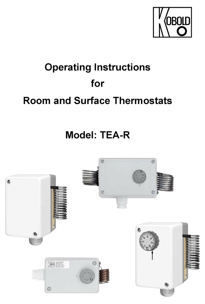
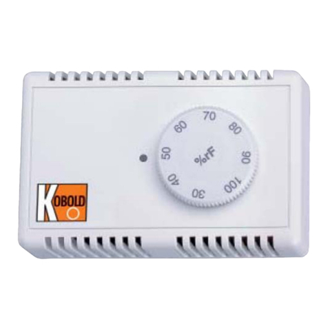
Kobold AFS-G2 User manual

Operating Instructions
for
Room Hygrostat
Model: AFS-G2

AFS-G2
page 2 AFS-G2 01/03
1. Contents
1. Contents........................................................................................................2
2. Note ..............................................................................................................3
3. Regulated Usage ..........................................................................................3
4. Operating Principle........................................................................................3
5. Instrument Inspection....................................................................................4
6. Mechanical Connection.................................................................................4
7. Electrical Connection ....................................................................................5
8. Operation ......................................................................................................6
9. Technical Data ..............................................................................................6
10. Order Codes .................................................................................................7
11. Maintenance .................................................................................................7
12. Dimensions ...................................................................................................8
13. Declaration of Conformance .........................................................................9
Manufactured and sold by:
Kobold Messring GmbH
Nordring 22-24
D-65719 Hofheim
Tel.: +49(0)6192-2990
Fax: +49(0)6192-23398
E-Mail: [email protected]
Internet: www.kobold.com

AFS-G2
AFS-G2 01/03 page 3
2. Note
Please read and take note of these operating instructions before unpacking and
operating the unit, and follow the instructions precisely as described herein.
The devices are only to be used, maintained and serviced by persons familiar
with these operating instructions and with any applicable regulations concerning
procedural safety and accident prevention.
When installed in machines, EWG commissioning is prohibited until it is
established that the machine meets the general requirements of the guideline.
3. Regulated Usage
The AFS-G2 is to be installed only in the specified applications. Every usage
which exceeds the specifications is considered to be non-specified. Any damages
resulting therefrom are not the responsibility of the manufacturer. The user
assumes all risk for such usage. The application specifications include the
installation, start-up and service requirements specified by the manufacturer.
4. Operating Principle
The room Hygrostat AFS-G2 is a two-position controller for regulating relative
humidity. The moisture sensing element in the sensor is comprised of several
strips of plastic fabric, each with 90 fibers of 3 µm diameter. These plastic fibers
undergo a special process to acquire hygroscopic properties, meaning that they
will both absorb and release moisture. The molecular structure of the fibers
changes when they absorb water, giving rise to a measurable change in length.
The length of the plastic fibers is thus a measure of the relative humidity. The
swelling effect, acting primarily in longitudinal direction, is transferred over a
suitable lever system to a microswitch with an extremely small changeover
movement (hysteresis).
The measuring element reacts quickly and accurately to the change in humidity.
The setpoint is set with the setpoint button so that the microswitch is actuated by
the lever system when the humidity setpoint is reached.
The special treatment of the measuring element ensures that its hygroscopic
properties remain stable, so that sensitivity is maintained unless destroyed by an
external influence.
The harp-shaped measuring element is mounted inside the housing and should
be protected against entry of coarse dust, dirt and water. The Hygrostat is
designed for unpressurized systems.

AFS-G2
page 4 AFS-G2 01/03
5. Instrument Inspection
These devices are inspected before shipping and sent out in perfect condition.
Should damage to a device be visible, we recommend a thorough inspection of
the delivery packing. In case of damage, please inform your parcel service/
forwarding agent immediately, as they are responsible for damage incurred
during transit.
Scope of delivery:
•Measuring Unit Model AFS-G2
•Operating Instructions
6. Mechanical Connection
•The Hygrostat must not be exposed to any direct water contact, e.g. splash
water when cleaning the air-conditioned room, etc.
•The place of installation must be selected so that a representative air humidity
measurement is guaranteed, i.e. the measured humidity values at the place of
installation should correspond to those of the room as closely as possible.
•If possible, the Hygrostat should be located in the airflow.
•The installation position should be chosen to prevent condensed water from
entering the housing. The instrument can be installed in any position, but the
ventilation slots should be at right angles to the wind direction if possible.
•The measurement location of the humidity controller should be selected such
that there is no build-up of condensate on or in the device. This applies
particularly for operation with a voltage higher than 48V. If the voltage is
higher, there is a risk of voltage arcing if there is water condensation on the
microswitch or connecting terminals, which might destroy the controller. In the
case of voltages below 48V, the humidity controller can be used up to
100%RH. The humidity controller should not be used in aggressive media.
•Mounting:
Physical Mounting: via slots in housing base.
Mounting position: Arbitrary, preferably with the ventilation slots at right angles
to the wind direction.

AFS-G2
AFS-G2 01/03 page 5
7. Electrical Connection
Important! Check that the electrical power supply to the instrument
complies with the operating data for the instrument.
•Make sure that the electrical power cables have been disconnected from the
supply.
•Connect the power supply and the output signal according to the connection
diagram shown below.
Fx = Relative humidity of the air (actual value)
Fw = Humidity adjusted on the knob (set value).
If the relative humidity (Fx) falls below the setpoint value (Fw), the contact 1-4
opens, and the contact 1-2 closes.
Approx. 5% RH

AFS-G2
page 6 AFS-G2 01/03
8. Operation
It is of extreme importance that the temperature is constant for measurements of
the relative air humidity. The air must be homogenous, e.g. possess constant
humidity and temperature for the entire duration of the measurement.
Influences of the relative air humidity
For a temperature fluctuation of ±1 °C referred to various room temperatures.
9. Technical Data
Physical details
Measuring Range: 30-100% RH
Measuring Accuracy: ±3.0% RH
Recommended
Operating Range: 35-100% RH
Differential Gap
(Microswitch): approximately 4% RH (at 50% RH)
Max. Voltage: 250 VAC
(Important! Use 250 V only when it is certain that no condensate will form on the
sensing element, as otherwise arcing can occur)
Switch contact
Contact Rating, Max. Capacity
Resistive Load: 5 A, 230 VAC
(service life of 50,000 cycles)
Max. Load for
"Humidification": 2 A
"Dehumidification": 5 A
Inductive Load (*) cosϕ=0.8: 0.2 A, 230 VAC
Inductive Load (*) L/R=3ms 1 A to 50 VDC
0.5 A to 75 VDC
Electric Bulb Load: 0.2 A to 50 VDC
Minimum Contact Rating: 100 mA, 20 VDC/AC
General
Allowed

AFS-G2
AFS-G2 01/03 page 7
Ambient Temperature: 0-60 °C
Average
Temperature Coefficient: -0.2%/K (at 20 °C and 50% RH)
Allowed Air Speed: 15 m/s
Half-life at v=2 m/s: 1.2 min
Contact: Connection terminals in housing
Electromagnetic compatibility:
Noise Immunity: EN 50 082-2
Emitted Interference: EN 50 081-2
Housing: Light Grey Plastic Housing
Protection: IP 20
Dimensions: 85 x 55 x 36 mm
Weight: Approximately 0.06 kg
*Check suitability!
10. Order Codes
Room Hygrostat AFS-G2
11. Maintenance
When the device is used in clean air, the measuring element is maintenance-
free. Aggressive and solvent vapors, depending on their type and concentration,
may cause faulty measurements and sensor failure. Water-repellent and
protective film-forming deposits on the sensor, like resin aerosols, lacquer
aerosols, fumigant substances etc., are harmful to almost all types of humidity
sensors and should be avoided.

AFS-G2
page 8 AFS-G2 01/03
12. Dimensions
% RH
4.5

AFS-G2
AFS-G2 01/03 page 9
13. Declaration of Conformance
We, KOBOLD-Messring GmbH, Hofheim-Ts, Germany, declare under our sole
responsibility that the product:
Hygrostat Model: AFS-G2..
to which this declaration relates is in conformity with the standards noted below:
EN 60730-2-1 1993
VDE 0631 2/09.89
IEC 730-2-1
Also the following EWG guidelines are fulfilled:
73/23 EWG Low voltage directive
89/336/EWG Electromagnetic compatibility
93/68 EWG Art. 13 (CE-symbol)
93/68 EWG Art.5
Signed: date: 29.10.02
H. Peters M. Wenzel
Other manuals for AFS-G2
1
Table of contents
Other Kobold Thermostat manuals
Popular Thermostat manuals by other brands

Megmeet
Megmeet MTC-04-NVT user manual

Honeywell
Honeywell TRADELINE T8090A owner's manual

Pro1 Technologies
Pro1 Technologies T855 Applications manual

Salus
Salus ERT50 instruction manual

Network Thermostat
Network Thermostat NetX Step By Step Installation Guide

Honeywell
Honeywell T6360B1036 GUIDE TO THE USE