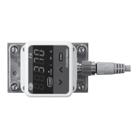
Koganei FA Series User manual

A thermal mass flow meter sensor enables
accurate measurement even in the case of
gas temperature and pressure fluctuations.
■Sensor
Sensor structure
Diaphragm
Downstream temperature
sensor
Upstream temperature sensor
Ambient temperature
sensor
Heater
Silicon chip
FLOW
Measurement principles
Temperature distribution
No flow state
Temperature distribution
Flow received state
FLOW
The FA Series flow meter measure flow rates using heat from the heater
and a temperature sensor. In a no flow state, the air temperature
distribution around the heater is uniform, so there is no difference in the
temperature between the upstream and downstream temperature sensor
positions. When flow is received in this state, the downstream temperature
rises while the upstream temperature falls, so a temperature difference
between the upstream and downstream sensor positions is generated.
This temperature different is measured and a flow rate is calculated.
■Rotary display
The display of the flow meter can be rotated 90°to the left or 180°to the right,
making it easy to read regardless of whether piping is horizontal or vertical.
Model Port size
Flow measurement range (±3% FS accuracy guaranteed range)R/min (normal)
FAS-002 Rc1/4
FAS-005 Rc1/2
FAS-030 Rc1
FAS-060 Rc1 1/2
FAS-120 Rc2
Note: Values in parentheses are flow measurement ranges for mounting directions 2 and 3. Refer to page 1675 for information about mounting directions.
4(10)
Note 200
240(600)
Note
12000
60(150)
Note 3000
120(300)
Note 6000
10(25)
Note 500
■Models
Practical measuring range of 50:1 (excluding some mounting directions) helps to provide an idea of air leaks.
Note: Do not try to rotate the display more than 90°to the left or 180°to the right.
90left
Standard position
180right 90right
FA Series
FLOW METERS
FLOW
3
調-補-真機器図面
初校
1636
旧版 1
032016

■Features
●Separation measurement using an orifice for large-volume flow measurement at each piping port and small
pressure load.
●A self-diagnostic function simplifies troubleshooting in the case of product trouble.
●In the case of the FAS-030, FAS-060, and FAS-120 models, replacement required in the case of malfunction
can be achieve by replacing the bypass unit only, without detaching piping. However, the ±3%FS guaranteed
accuracy of the replacement product becomes ±5%FS.
●Range extension function
The FA Series flow meter displays up to double the maximum flow measurement range, and support analog
output and switch output.
However, the measurement accuracy of the additional part is approximately ±10%RD.
●Reverse flow detection function
FA Series flow meters can display a reverse flow (flow in the opposite direction from unit's flow arrow) up to 30% of the
maximum flow measurement range, and flow integration. However, reverse flow measurement accuracy is approximately
±6%FS, and analog output and switch output (except for some integrating functions) is not possible.
Example of use
Flow measurement
between lines and
divisions enables
division-specific cost
allocation. It also
helps to avoid over
use of air.
Knowing the flow over
time provides a means to
reduce power consumption
by optimization of
compressor operations
(load, unload, power off).
The integrated
reverse flow makes it
possible to integrate
reverse flows as well.
A wide flow measurement
range makes it possible to
obtain an understanding
of line stoppage time and
the amount of leakage.
*
Remark: RD stands for "reading" (read value). With the FAS-002, error is ±30 ℓ/min (ANR) [±1.06 ft3/min] (normal)
for an instantaneous flow display of 300 ℓ/min (ANR) [10.6 ft3/min] (normal) and error is ±40 ℓ/min (ANR) [±1.413
ft3/min] (normal) for an instantaneous flow display of 400 ℓ/min (ANR) [14.1 ft3/min] (normal).
The results of air
consumption
reduction is readily
apparent from values
that are produced.
3
調-補-真機器図面
初校
1637
旧版 2
032016

Safety Precautions (Flow Meters FA Series)
DANGER
●Do not attempt any adjustment (connecting or disconnecting
wire connectors, piping work, etc.) to mechanisms attached to
the product while the product is operating. Abnormal operation
creates the risk of personal injury.
WARNING
●Do not apply external magnetic field to the flow meter while it
is operating. Unintended operations could damage equipment
or cause injury.
●When wiring, take care to ensure that wiring polarity is correct.
Incorrect polarity could result in damage to the flow meter.
CAUTION
●Do not subject flow meter cables that have connectors to
excessive loads by pulling on them, lifting the product by
them, or by placing heavy objects on them. Doing so may
cause current leakage or defective continuity leading to fire,
electric shock, or abnormal operation.
●While handling the flow meter, do not subject them to
excessive shock (490 m/s2[50 G] or greater) by hitting,
dropping or bumping it. Even if the product appears
undamaged, damage to internal components can cause
abnormal operation.
●Avoid short circuiting loads.
Turning on switch output while a load short-circuit condition
exists can cause damage to the flow meter due to over
current.
Load short-circuit example: output lead of switch output
connected to DC power supply.
The safety precautions below are specific to FA Series flow
meters. For other safety precautions in addition to the infor-
mation below, also be sure to read the safety precautions at
the front of the general personal catalog.
Handling Instructions and Precautions
General precautions
Mounting location
Avoid installing the FA Series Flow Meter in the following types of locations.
1.
Locations where the ambient temperature or product temperature is -10℃
[14℉] or lower, or exceeds 60℃[140℉].
2.
Locations where the ambient humidity exceeds 90%RH.
3.
Locations subjected to sudden temperature changes that can cause
condensation.
4.
Locations subjected to concentrations of corrosive and/or flammable gasses.
5.
Locations subjected to high amounts of dust, salt, iron powder, or other
conductive matter, moisture, oil mist, or organic solvents.
6.
Locations where the product is directly subjected to vibration and/or impact.
7.
Locations exposed to direct sunlight.
8.
Locations where water, rain, or other moisture can get on the product.
9.
Locations where oil or chemicals can get on the product.
10.
Locations that are always wet or dusty, or subject to water or dust.
11.
Locations where strong magnetism or strong electric fields are being
generated.
Operation outside the maximum flow range
When the flow rate exceeds the maximum flow rate range of the FA
Series Flow Meter, the alarm message " " will alternate on the
display with the flow rate reading. Always use this flow meter within the
specified maximum flow rate range.
Mounting and piping
Piping
1.
The FA Series Flow Meter is a precision instrument. Take care when handling
it. It can be damaged by dropping it or otherwise subjecting it to strong impact.
2.
Whenever connecting piping to the FA Series Flow Meter, make sure that the
direction of the arrow marked on it matches the flow direction of the fluid.
3.
When connecting piping, do not apply force to the bypass unit section.
4.
When connecting piping, secure the main flow channel and rotate the pipe to
the suitable tightening torque range.
Model
FAS-002
FAS-005
FAS-030
FAS-060
FAS-120
Port size
Rc
1/4
1/2
1
1 1/2
2
Suitable tightening torque
N•m [in•lbf]
12 to 14 [106.212 to 123.914]
31 to 33 [274.381 to 292.083]
36 to 38 [318.636 to 336.338]
59 to 61 [522.209 to 539.911]
74 to 76 [654.974 to 672.676]
Bypass unit
Main flow path
5.
Take care to keep foreign matter from flowing into the FA Series Flow Meter.
Any rust, water droplets, oil mist, dust, or other foreign matter inside piping
that gets into the FA Series Flow Meter creates the risk of measurement
error and damage to the flow meter. Before installation, be sure to thoroughly
flush both the upstream and downstream piping (pipe cleaning) and check to
make sure there is no foreign matter present.
3
調-補-真機器図面
初校
1638
旧版 4
032016

Handling Instructions and Precautions
Mounting direction 1: With horizontal piping, display upwards. (Standard direction)
Mounting direction 2:
Horizontal piping with the display on the right when viewed from the
flow meter IN side pipe. When using this installation attitude, set the
low flow cut parameter value to 5. Failure to do so will cause the flow
rate to be displayed (output) even when there is no fluid flowing. The
normal flow side and back flow side integral functions activate, causing
the flow rate values to be integrated.
Mounting direction
Side diagram
Direction of flow
Up
Down
Note: "FS flow" is the full scale flow.
Example.
At a pressure of 0.3 MPa when the flow meter is installed on horizontal piping with the display
facing to the right, when viewed from the flow meter IN side pipe, causes a change in the flow
rate that is no more than 1. 5% FS ±1 digit compared to the normal installation attitude.
0.5[% FS/0.1 MPa]×0.3[MPa]=1.5[%FS]
Operating pressure range
0 to 1 MPa [0 to 145 psi]
-0.07 to 0 MPa [-10 to 0 psi]
Flow range
5 to 100% of FS flow
Note
5 to 100% of FS flow
Instantaneous flow display change volume
0.5% FS/0.1 MPa [1.5 psi]±1 digit or lower
0.5% FS/0.01 MPa [1 psi]±1 digit or lower
Up
Down
Direction of flow
Side diagram
Viewed from IN side piping.
mode
enter
ALEVLL/min
FA
Mounting direction 3: Horizontal piping mounting with display leftwards relative to
the flow level meter IN size pipe. When using this
installation attitude, set the low flow cut parameter value to
5. Failure to do so will cause the flow rate to be displayed
(output) even when there is no fluid flowing. The normal
flow side and back flow side integral functions activate,
causing the flow rate values to be integrated.
Mounting direction 4: With horizontal piping, display downwards.
Do not use this mounting direction.
Mounting direction 5: With vertical piping
Up
Down
Direction of flow
Direction of flow
mode
enter
ALEVLL/min
FA
mode
enter
ALEVLL/min
FA
Up
Down
Direction of flow
Side drawing
Viewed from IN
side piping.
Up
Down Side diagram
Direction of flow
Operating pressure range
0 to 1 MPa [0 to 145 psi]
-0.07 to 0 MPa [-10 to 0 psi]
Flow range
5 to 100% of FS flow
Instantaneous flow display change volume
-0.5% FS/0.1 MPa [1.5 psi]±1 digit or lower
-0.5% FS/0.01 MPa [1 psi]±1 digit or lower
Example At a pressure of 0. 3 MPa when the flow meter is installed on horizontal
piping with the display facing to the right when viewed from the flow
meter IN side pipe, causes a change in the flow rate that is no more
than −1. 5% FS ±1 digit compared to the normal installation attitude.
-0.5[%FS/0.1 MPa]×0.3[MPa]=-1.5[%FS]
6.
When connecting piping, apply an appropriate amount of sealant. Do not apply
sealant to the first two threads of the end of the pipe. Over-application of sealant can
cause it to get inside the piping, creating the risk of measurement error and damage
to the FA Series Flow Meter.
7.
If different-diameter piping, a regulator, filter, valve, or other piping equipment is
installed upstream from the FA Series Flow Meter, be sure to provide a straight pipe
section as recommended. See "Specification accuracy and straight pipe section" for
more information. Failure to provide a straight pipe section can cause flow rate errors.
8.
Connecting expansion pipe or a tube coupler without providing a straight pipe
section can produce a negative flow rate reading due to back flow in bypass unit,
even though there is normal flow as far as the product is concerned.
9.
Installing the display section on horizontal piping so it is in a downward orientation
may cause rust, water droplets, oil mist, dust, or other foreign matter to adhere to
the sensor, creating the risk of measurement errors and damage to the FA Series
Flow Meter. Do not use the display section in a downward orientation.
Installing the display section on horizontal piping in a sideways orientation will cause
errors due to the effect of the attitude. For details, see "Installation Attitudes" below.
10.
Do not install in locations where the effects of pulsating flow or flow maldistribution
are present, such as in the vicinity of the compressor delivery port, on bellows
piping, etc. Also, do not install in a location where a regulator or check valve is
performing hunting. Doing so creates the risk of measurement error.
D
i
r
e
c
t
i
o
n
o
f
w
r
a
p
p
i
n
g
Leave 2 threads open.
S
e
a
l
i
n
g
t
a
p
e
Liquid
sealant
3
調-補-真機器図面
初校
1639
旧版 5
032016

Note 4: Contact Koganei for information about 1 1/2B and 2B size filters and mist filters.
5: Required direct piping when connecting a filter with the same diameter as the flow meter.
6: A reduction pipe connection example (within the product specification range (±3%FS)) for
the FAS-002 is shown below.
When connecting one size larger piping (for example, 1/2B for the FAS-002), take the
specified value*+5D for direct piping before the flow meter and the specified value*+5D for the
direct piping after the flow meter.
* Piping length when connecting piping one size larger than the specified value.
7: A reduction pipe connection example (within the product specification range (±3%FS)) for
the FAS-005is shown below.
Do not connect piping that is thinner than the connection port without direct piping. Reverse
flow by the bypass unit is possible even though the product is providing normal direction
flow, and produce a negative reading on the flow display. Or an extremely low flow value
may be displayed in place of the actual flow.
Or when connecting one size smaller piping (for example, 1/4B for the FAS-005), take the
specified value*+10D for direct piping before the flow meter and the specified value*+5D for
the direct piping after the flow meter.
* Piping length when connecting piping one size smaller than the specified value.
8: Reference diagrams for a single elbow and double elbow are shown below.
9: Install valves for flow adjustment downstream from the flow meter.
10:Install when the distance from the flow meter is greater than the specified distance. It makes
no difference whether piping from the regulator to the flow meter is constructed of tubing or
an elbow bend. However, install the required direct piping when connecting with the flow
meter with an elbow bend. Allow for distance even if a filter or mist filter is inserted.
5D
FAS-002
1/4B3/8B 3/8B
10D 5D
FAS-002
1/2B 1/4B 1/4B 1/2B
15D
FAS-005
1/2B3/8B 3/8B
25D 5D
FAS-005
1/2B1/4B 1/2B 1/4B
10D Single elbow
10D Double elbow
Elbow
Distance from flow meter
FAS-002: 200D or more
Other machines: 30D or more
Straight pipe minimum
of 10D
Regulator
mode
enter
ALEVLL/min
FA
Filter
•
Whenever there is the risk of foreign matter (dust, sediment, oil mist, etc.) being
mixed in with the measured fluid, be sure to install upstream from the FA Series Flow
Meter a filter and mist filter that can remove foreign matter measuring 1μm or larger.
•
Periodically inspect and replace filters, and perform other periodic maintenance as
required.
Specification accuracy and pipe section
Install the FA Series Flow Meter so the arrow marked on its label is pointed in the
same direction as the fluid flow direction. When connecting different diameter tubing,
valves, filters, and other equipment, provides straight pipe in accordance with the
information in the table below.
A "straight pipe" is straight piping that is the same bore diameter as the flow meter.
The following types of pipes are suitable as straight pipe: carbon steel pipes for
ordinary piping (JIS G3452), carbon steel pipes for pressure service (JIS G3454),
Schedule 40 or less, and stainless steel pipes (JIS G3459), Schedule 40.
Note1
For equipment not included in the table below, provide 15D or larger straight piping
when installing it upstream from the FA Series Flow Meter, and 5D or larger straight
piping when installing it downstream from the FA Series Flow Meter. The letter D
represents the bore diameter.
Note2
When measuring back flow in addition to normal flow, the same length as the
upstream straight pipe is required downstream from the FA Series Flow Meter.
Note 1: Note that accuracy deteriorates when piping carbon steel pipes for pressure
service (JIS G3454) or stainless steel pipes (JIS G3459), larger than Schedule 40
is connected. A larger schedule results in a smaller pipe inside diameter which
causes a pipe effect and deteriorated accuracy.
2: The approximate D (bore diameter) for FAS-002 (1/4B) is 8 mm [0.315 in], for
FAS-005 (1/2B) is 15 mm [0.591 in], for FAS-030 (1B) is 25 mm [0.984 in], for
FAS-060 (1 1/2B) is 40 mm [1.575 in], and for FAS-120 (2B) is 50 mm [1.969 in].
3: Always provide a filter upstream from the mist filter.
Piping, connection equipment Connection
location
Straight pipe section with FA Series flow meter
Specification ranges
Within ±3%FS
Accuracy
Within ±5%FS
Mist filter
For FAS-002, FAS-005, FAS-030
Note3, 5
Upstream from
flow meter
10D Not required
Mist filter
For FAS-060, FAS-120Note4, 5
Upstream from
flow meter
20D Not required
1-size large port diameter piping
(Reduction pipe connection)
FAS-002 3/8B→1/4B
FAS-005 3/4B→1/2B
FAS-030 1 1/4B→1B
FAS-060 2B→1 1/2BNote6
Upstream from
flow meter
5D Not required
Downstream
from flow meter
Not required Not required
1-size larger port diameter piping
(Reduction pipe connection)
FAS-120 2 1/2B→2BNote6
Upstream from
flow meter
10D 5D
Downstream
from flow meter
5D 5D
1-size small port diameter piping
(Expansion pipe connection)
FAS-002 1/8B→1/4B
FAS-005 3/8B→1/2B
FAS-030 3/4B→1B
FAS-060 1 1/4B→1 1/2BNote7
Upstream from
flow meter
15D Not required
Downstream
from flow meter
Not required Not required
More than 1-size smaller small port diameter piping
(Expansion pipe connection)
FAS-120 1 1/2B→2B
Note7
Upstream from
flow meter
25D 10D
Downstream
from flow meter
5D 5D
Single elbowNote8
Upstream from flow meter
10D Not required
Downstream from flow meter
Not required Not required
Double elbowNote8
Upstream from flow meter
10D 10D
Downstream from flow meter
Not required Not required
Ball valve
(Fully open elbow type)Note9
Upstream from flow meter
20D 10D
Downstream from flow meter
10D 5D
RegulatorNote10
FAS-002
Upstream from flow meter
200D Not required
Downstream from flow meter
10D Not required
RegulatorNote10
FAS-005, FAS-030, FAS-060,
FAS-120
Upstream from flow meter
30D Not required
Downstream from flow meter
5D Not required
Air filter
Upstream from flow meter
25D Not required
Handling Instructions and Precautions
3
調-補-真機器図面
初校
1640
旧版 6
032016

•For connection with a quick fitting
Provide the straight pipe section noted in the table below when
connecting the FA Series Flow Meter to a quick fitting.
Connecting without a straight pipe section can produce a
negative reading due to bypass unit back flow, even if flow in the
main channel itself is normal direction flow. Also, the readout may
show an extremely low flow rate instead of the actual flow rate.
Quick fitting
Direct piping
Tube
Direction of flow
Piping, connection
equipment
Connection
location
Straight pipe section with FA Series flow meter
Specification ranges
Note
Within ±3%FS
Accuracy
Note
Within ±5%FS
Quick fitting
Tube sizeφ8 [0.315 in]
(With FAS-002)
Upstream from
flow meter
15D 5D
Downstream
from flow meter
Not required Not required
Upstream from
flow meter
20D 10D
Downstream
from flow meter
5D 5D
Quick fitting
Tube sizeφ12 [0.472 in]
(With FAS-002)
Upstream from
flow meter
5D Not required
Downstream
from flow meter
Not required Not required
Upstream from
flow meter
10D 5D
Downstream
from flow meter
5D 5D
Quick fitting
Tube sizeφ12 [0.472 in],
φ16 [0.63 in]
(With FAS-005)
Upstream from
flow meter
10D 5D
Downstream
from flow meter
Not required Not required
Upstream from
flow meter
15D 10D
Downstream
from flow meter
5D 5D
Quick fitting
Tube sizeφ12 [0.472 in],
φ16 [0.63 in]
(With FAS-030)
Upstream from
flow meter
10D 8D
Downstream
from flow meter
5D 5D
Upstream from
flow meter
15D 13D
Downstream
from flow meter
10D 10D
Note: Characteristics for connection when tubing from fitting is virtually
straight for approximately 300 mm [11.8 in].
Connections
1.
Use a power supply that is within the specification range.
2.
Wire a cable with connector separately from power lines and high voltage
lines (use a separate conduit). Noise from these lines may cause the
equipment to operate erratically.
3.
When connecting a cable with connector, align the core wire and push it in as
far as it will go. Next, tighten the connector nut by hand. When tightening the
nut, be sure to keep it within the prescribed torque (0.4 to 0.6 N·m [3.540 to
5.311 in·lbf] range). Failure to do so creates the risk of damage to the FA
Series Flow Meter and inability to maintain the IP65 protective structure, and
loosening of the nut due to vibration.
4.
Do not pull on the cable with strong force and do not lift the FA Series Flow Meter
by the cable (pull out strength: 40 N [8.992 lbf] or less; bend strength; 20 N [4.496
lbf] or less). Also, do not subject the cable to repeated bending or pulling force.
5.
Do not rotate the center part of the connector (see figure below) while the
connector is inserted fully into the FA Series Flow Meter. Doing so will cause
the FA Series Flow Meter connector to rotate, which can cause internal wiring
to twist and become damaged.
Cable with connector
Connector root
Connector nut
mode
enter
ALEVLL/min
FA
6.
Always turn off the power supply before doing any wiring.
7.
Keep load resistance connected to the instantaneous flow rate output below 300 Ω.
8.
Keep cable and connector ends away from moisture when doing wiring.
9.
Double-check to make sure that wiring is correct before turning on power.
Wiring error creates the risk of damage and erratic operation.
1
2
3
4
V
+
(brown)
I
+
(white)
COM (blue)
EV (black)
Instantaneous
flow output
4 to 20mA
Allowable load
resistance
300 Ωor less
22.8 to
25.2 VDC
30 VDC or less
30 VDC,
50 mA or less
Example external connectionInner circuit
Load
Load
+
−
+
−
●Example connection
Key
1
2
34
Pin number
1
2
3
4
Signal name
V+
I+
COM
EV
Description
24 VDC
Instantaneous flow output (4 to 20 mA)
COM
Switch output
Pin number
1
2
3
4
Signal name
V+
I+
COM
EV
Wire colors
Brown
White
Blue
Black
Relationship between connector cable colors and pin numbers
Filling
type
Straight
type
Straight
type
Straight
type
Straight
type
Elbow
type
Elbow
type
Elbow
type
Elbow
type
3
調-補-真機器図面
初校
1641
旧版 7
032016

-0.07 〜1.0 MPa [-10 〜145 psi] (gauge pressure)
-10 〜+60°C [14 〜140°F] (non-freezing)
0 〜90% RH (Non-condensation)
-20 〜+70°C [-4 〜158°F] (non-freezing)
0 〜90% RH (Non-condensation)
1.5 MPa [218 psi] (gauge pressure)
100 ml/h (normal) (When internal flow meter pressure is 1.5 MPa [218 psi])
24 VDC
22.8 〜25.2 VDC
120mA Max.
50±5ms (when shipped)
Specifications
Model
Item FAS-002
4 〜200 (10 〜200)
[0.141 〜7.1 (0.353 〜7.1)]
2 [0.071]
−60 〜400 [−2.119 〜14.1]
1 [0.035]
10 [0.353]
−60 〜400 [-2.119 〜14.1]
−
3.6 〜24.0
−
0.060 〜0.400
−
4.7 〜31.0
10 〜500 (25 〜500)
[0.353 〜17.7 (0.883 〜17.7)]
5 [0.177]
−150 〜1000 [−5.3 〜35]
1 [0.035]
10 [0.353]
−150 〜1000 [−5.3 〜35]
−
9.0 〜60.0
−
0.150 〜1.000
−
11.6 〜77.6
60 〜3000 (150 〜3000)
[2.119 〜106 (5.3 〜106)]
30 [1.060]
−900 〜6000 [−31.8 〜212]
5 [0.177]
10 [0.353]
-900 〜6000 [-31.8 〜212]
−
54.0 〜360
−
0.900 〜6.000
−
70 〜465.5
120 〜6000 (300 〜6000)
[4.2 〜212 (10.6 〜212)]
60 [2.119]
−1800 〜12000 [−64 〜424]
10 [0.353]
100 [3.5]
−1800 〜12000 [−64 〜424]
−
108.0 〜720.0
−
1.800 〜12.000
−
140.0 〜931.0
240 〜12000 (600 〜12000)
[8.5 〜424 (21.2 〜42.4)]
120 [4.2]
−3600 〜24000 [−127 〜848]
10 [0.353]
100 [3.5]
−3600 〜24000 [−127 〜848]
−
220.0 〜1440.0
−
3.600 〜24.000
−
279.0 〜1862.0
FAS-005 FAS-030 FAS-060 FAS-120
Air, nitrogen
However, dry air that does not include corrosive elements (salt, sulfur, acid, etc.)
Clean gas that does not include dust and/or oil mist
( )
±3% FS ±1digit (2 〜100% of FS flow, 5 〜100% in the case of mounting directions 2 and 3)Note9
±6% FS (-30 〜0% of FS flow)
±10% RD (100 〜200% of FS flow)Note7
±1.0% FS ±1digit (2 〜100% of FS flow)
±2% FS (-30 〜0% of FS flow)
±10% RD (100 〜200% of FS flow)Note7
±0.15% FS/°C ±1digit or lower
-0.25% FS/0.1 MPa [1.5 psi]±1digit or lower (2 〜40% of FS flow)
-0.55% FS/0.1 MPa [1.5 psi]±1digit or lower (40 〜100% of FS flow)
0.5% FS/0.1 MPa [1.5 psi]±1digit or lower (5 〜100% of FS flow)
0.5% FS/0.01 MPa [1 psi]±1digit or lower (5 〜100% of FS flow)
-0.5% FS/0.1 MPa [1.5 psi]±1digit or lower (5 〜100% of FS flow)
-0.5% FS/0.01 MPa [1 psi]±1digit or lower (5 〜100% of FS flow)
Current output, 1 point: 4-20mA (Output range: 3.2 〜20.8 mA)
Alarm time fixed output (up): 21.6±0.4 mA (Default, can be changed by setting)
Alarm time fixed output (down): 0.0±0.4mA fixed
Allowable load resistance: 300Ωor less
Maximum output current: 24 mA
Within 1.5s (Time 〜reach 95% of final value upon step input of 0 〜100%FS; Calculation cycle: 50 ms)
Rc1/4 Rc1/2 Rc1 Rc1 1/2 Rc2
Open collector output, 1 point: 30 VDC, 50 mA or less
One of the functions below can be selected.
•Instantaneous flow upper limit, lower limit, range
•Integrated flow count up, count down
•Alarm generation
•Integration pulse output (3-level selectable pulse weight)
Media
Port size
Flow measurement range
Note6
ℓ/min (normal) [ft
3
/min]
Minimum sensitivity flow
ℓ/min (normal) [ft
3
/min]
Maximum flow range
ℓ/min (normal) [ft
3
/min]
Display resolution
Note5
Instantaneous flow
ℓ/min (normal) [ft3/min]
Integrated flow
ℓ/min(normal) [ft
3
/min]
Maximum display range
m3/h (normal)
m3/min(normal)
kg/h
Instantaneous flow display accuracy
Instantaneous flow display repeatability
Temperature characteristics
Operating pressure
0 to 1 MPa [0 to 145 psi]
Operating pressure
-0.07 to 0 MPa [-10 to 0 psi]
Operating pressure
0 to 1 MPa [0 to 145 psi]
Operating pressure
-0.07 to 0 MPa [-10 to 0 psi]
Operating pressure
0 to 1 MPa [0 to 145 psi]
Operating pressure
-0.07 to 0 MPa [-10 to 0 psi]
Operating pressure range
Operating temperature range
Operating humidity range
Storage temperature range
Storage humidity range
Proof pressure
Amount of external leakage
Rated voltage
Power supply voltage range
Consumption current
Calculation cycle
Instantaneous flow outputNote10
Response time
Switch outputNote11
±0.25% FS/0.01 MPa [1 psi]±1digit or lower (2 〜40% of FS flow)
±0.55% FS/0.01 MPa [1 psi]±1digit or lower (40 〜100% of FS flow)
Instantaneous flow display
change volume by mounting
direction 2 Note 8
Instantaneous flow display
change volume by mounting
direction 3 Note 8
Pressure characteristics
3
調-補-真機器図面
初校
1642
旧版 8
032016

Note 1: (normal) is a value converted to a 0°C [32°F], 101.325 kPa [29.9 inHg] (abs) flow.
2: "FS flow" is the maximum flow of the flow measurement range.
3: "RD" stands for "reading" (read value).
4: A minus (−) flow rate value indicates a back flow rate (flow in the direction opposite that indicated by the flow meter arrow).
5: Regardless of the unit of display and the decimal point position, this indicates resolution from the lowest display digit.
6: A flow rate inside of parentheses ( ) is for installation attitudes 2 and 3.
7: This accuracy is a value representing instantaneous flow rate display accuracy along with instantaneous display repeatability.
8: See the installation attitudes on page 1675.
9: Replacing the bypass unit with a new unit causes instantaneous flow rate display accuracy to become ±5%FS ±1 digit. (FAS-030, FAS-060, FAS-120)
10: The back flow side cannot output.
11: Back flow side settings cannot be configured.
0.4 [0.882] 0.4 [0.882] 0.5 [1.102] 0.7 [1.543] 1.1 [2.425]
Specifications
FAS-002 FAS-005 FAS-030 FAS-060 FAS-120
Model
Item
Order Codes
Additional Parts
●Bypass unit
(For FAS-030, -060, -120 only.)
FAB
■Cable with connector (Azbil Corporation)
PA5-4ISX2SK
PA5-4ISX5SK
(Cable length: 2000 mm [79 in])
(Cable length: 5000 mm [197 in])
FAS - - --
Mounting bracketNote
Blank : None
B : With mounting bracket
Note: Mounting brackets are for FAS-002, -005, and -030 only.
Flow rate ranges
002: 0 to 200 ℓ/min(normal) [0 to 7.1 ft
3
/min]
005: 0 to 500 ℓ/min(normal) [0 to 17.7 ft
3
/min]
030: 0 to 3000 ℓ/min(normal) [0 to 106 ft
3
/min]
060: 0 to 6000 ℓ/min(normal) [0 to 212 ft
3
/min]
120: 0 to 12000 ℓ/min(normal) [0 to 424 ft
3
/min]
Flow Meters
FA series
Length of cable with connecto
r
Blank: no cable
2L : 2000 mm [79 in]
5L : 5000 mm [197 in]
Inspection report
Blank : None
T :
Inspection report appended
Data recording
Dielectric strength
Insulation resistance
Cable
Mounting direction
Protective structure
Main flow path
Gas contact part material
Bypass unit
Gasket
Bypass unit case material
Load mass kg [lb]
Semiconductor non-volatile memory EEPROM
Recorded data: Function settings, parameters, integrated values, etc.
Leakage current of 1 mA or less
500 VAC applied for one second between the connector pin and main flow path or mounting bolt
50 MΩor more
500 VDC megger applied for one second between the connector pin and main flow path or mounting bolt
Option (with connector, oil resistant, flame retardant cable; UL2464EN standard)
Refer to "Mounting direction" on page 1675.
IP65 (JISC0920 and IEC529); splash resistant and dust resistant, assuming indoor installation)
Aluminum alloy (anodized)
SUS304, PBT, H-NBR (hydrogenated nitrile rubber)
H-NBR (hydrogenated nitrile rubber)
Denatured PPO
●Mounting bracket
(For FAS-002, -005, -030 only.)
B-FAS
3
調-補-真機器図面
初校
1643
旧版 9
032016

Pressure Loss
●FAS-002
50 2000 100 150
Flow volume R/min (normal)
6
2
4
0.1MPa
Primary side pressure
0.7MPa
0.3MPa
0.5MPa
0100 4000 200 300
Flow volume R/min (normal)
20
5
10
15
0.1MPa
Primary side pressure
0.7MPa
0.3MPa
0.5MPa
0
Pressure loss kPa
Pressure loss kPa
●FAS-005
100 5004000 200 300
Flow volume R/min (normal)
15
5
10
0.1MPa
Primary side pressure
0.7MPa
0.3MPa
0.5MPa
0200 10008000 400 600
Flow volume R/min (normal)
60
20
40
0.1MPa
Primary side pressure
0.7MPa
0.3MPa
0.5MPa
0
Pressure loss kPa
Pressure loss kPa
●FAS-030
500 300025002000
0
1000 1500
Flow volume R/min (normal)
20
5
10
15 0.1MPa
Primary side pressure
0.7MPa
0.3MPa
0.5MPa
0
1000 60005000400002000 3000
Flow volume R/min (normal)
0.1MPa
Primary side pressure
0.7MPa
0.3MPa
0.5MPa
0
80
20
40
60
Pressure loss kPa
Pressure loss kPa
●FAS-060
20
5
10
15 0.1MPa
Primary side pressure
0.7MPa
0.3MPa
0.5MPa
0
1000 600050004000
0
2000 3000
Flow volume R/min (normal)
0.1MPa
Primary side pressure
0.7MPa
0.3MPa
0.5MPa
0
80
20
40
60
2000 120001000080000 4000 6000
Flow volume R/min (normal)
Pressure loss kPa
Pressure loss kPa
●FAS-120
0.1MPa
Primary side pressure
0.7MPa
0.3MPa
0.5MPa
0
25
5
10
15
20
2000 12000100008000
0
4000 6000
Flow volume R/min (normal)
0.1MPa
Primary side pressure
0.7MPa
0.3MPa
0.5MPa
0
100
20
40
60
80
4000 240002000016000
0
8000 12000
Flow volume R/min (normal)
Pressure loss kPa
Pressure loss kPa
1kPa = 0.2954 inHg
1 ℓ/min (ANR) =
0.03532 ft3/min (SCFM)
1 MPa = 145 psi
1kPa = 0.2954 inHg
1 ℓ/min (ANR) =
0.03532 ft3/min (SCFM)
1 MPa = 145 psi
1kPa = 0.2954 inHg
1 ℓ/min (ANR) =
0.03532 ft3/min (SCFM)
1 MPa = 145 psi
1kPa = 0.2954 inHg
1 ℓ/min (ANR) =
0.03532 ft3/min (SCFM)
1 MPa = 145 psi
1kPa = 0.2954 inHg
1 ℓ/min (ANR) =
0.03532 ft3/min (SCFM)
1 MPa = 145 psi
1kPa = 0.2954 inHg
1 ℓ/min (ANR) =
0.03532 ft3/min (SCFM)
1 MPa = 145 psi
1kPa = 0.2954 inHg
1 ℓ/min (ANR) =
0.03532 ft3/min (SCFM)
1 MPa = 145 psi
1kPa = 0.2954 inHg
1 ℓ/min (ANR) =
0.03532 ft3/min (SCFM)
1 MPa = 145 psi
1kPa = 0.2954 inHg
1 ℓ/min (ANR) =
0.03532 ft3/min (SCFM)
1 MPa = 145 psi
1kPa = 0.2954 inHg
1 ℓ/min (ANR) =
0.03532 ft3/min (SCFM)
1 MPa = 145 psi
3
調-補-真機器図面
初校
1644
旧版 10
032016

Dimensions mm [in]
FAS-002 : 2-Rc1/4
FAS-005 : 2-Rc1/2
(Mounting screw hole)
2-M4×0.7, depth 7 [0.276]
(46.5 [1.831])
15 [0.591]
34 [1.339]
75 [2.953] 47 [1.850]
13.5 [0.531]
24 [0.945]
48 [1.890]
27 [1.063]
65.8 [2.591]
1.5 [0.059]
73.8 [2.906]
23.5 [0.925]
IN OUT
(φ
6 [0.236])
90 [3.543]
78 [3.071]
75 [2.953]
63 [2.480]
4.5 [0.177]
5.5 [0.217]
Mounting bracket (-B)
M12 Connector
( )
Cable with connector (option)
-2L: Cable length 2000 mm [79 in]
-5L: Cable length 5000 mm [197 in]
2-Rc1
48 [1.890]
23.5 [0.925]
(60.5 [2.382])
90 [3.543]
13.5 [0.531]
24 [0.945]
48 [1.890]
27 [1.063]
79.8 [3.142]
1.5 [0.059]
47 [1.850]
23.5 [0.925]
( )
Cable with connector (option)
-2L: Cable length 2000 mm [79 in]
-5L: Cable length 5000 mm [197 in]
(φ
6 [0.236])
M12 Connector
IN OUT
(Mounting screw hole)
2-M4×0.7, depth 7 [0.276]
87.8 [3.457]
90 [3.543]
78 [3.071]
75 [2.953]
63 [2.480]
4.5 [0.177]
5.5 [0.217]
Mounting bracket (-B)
●FAS-030
●FAS-002•FAS-005
3
調-補-真機器図面
初校
1645
旧版 11
032016

2-Rc1 1/2
30.5 [1.201]
61 [2.402]
17 [0.669]
34 [1.339]
60 [2.362]
93.8 [3.693]
100 [3.9]
62 [2.441]
(74.5 [2.933])
30 [1.181]
30 [1.181]
( )
Cable with connector (option)
-2L: Cable length 2000 mm [79 in]
-5L: Cable length 5000 mm [197 in]
(φ
6 [0.236])
M12 Connector
(Mounting screw hole)
2-M5×0.8, depth 7 [0.276]
IN OUT
●FAS-060
2-Rc2
34 [1.339]
17 [0.669]
61 [2.402]
30.5 [1.201]
110 [4.3]
106.8 [4.2]
75 [2.953]
37.5 [1.476]
75 [2.953]
(87.5 [3.445])
37.5 [1.476]
( )
Cable with connector (option)
-2L: Cable length 2000 mm [79 in]
-5L: Cable length 5000 mm [197 in]
(φ
6 [0.236])
M12 Connector
(Mounting screw hole)
2-M5×0.8, depth 7 [0.276]
OUTIN
●FAS-120
Dimensions mm [in]
3
調-補-真機器図面
初校
1646
旧版 12
032016

4-φ5.5 [0.217]
72 [2.835]
61 [2.402]
34 [1.339]
45 [1.772]
(1 [0.039])
(6 [0.236])
51 [2.008] (11.5 [0.453])
(12.5 [0.492])
31.8 [1.252]
3 [0.118]
4.5 [0.177]
1.5 [0.059]
8 [0.315]
27 [1.063]
5.5 [0.217]
50 [1.969]
63 [2.480]
75 [2.953]
4-φ4.5 [0.177]
Cross head pan screw
M4×0.7 Length6 [0.236] Two attached
48 [1.890]
78 [3.071]
90 [3.543]
Additional Parts Dimensions mm [in]
(φ
6 [0.236])
(φ
14 [0.551])
(40 [1.575]) (40 [1.575])
( )
PA5-4ISX2SK : 2000 [79]
PA5-4ISX5SK : 5000 [197]
●Bypass unit FAB
●Mounting bracket B-FAS
■Cable with connector PA5-4ISX2SK (Cable length: 2000 mm [79 in])
(Azbil Corporation) PA5-4ISX5SK (Cable length: 5000 mm [197 in])
3
調-補-真機器図面
初校
1647
旧版 13
032016

mode
enter
ALEVLL/min
FA
Display
Connector
Main flow path
IN
Bypass unit
Mounting bolts
q
rt
w
e
y
OUT
Setting Guidelines
Nomenclature and functions
①
Flow rate display :
5-digit, 7-segment LED that normally shows the
instantaneous flow rate and integrated flow rate.
For integrated flow rate, the displayed value is
divided between the four highest digits and five
lowest digits. In setting mode, the display shows
setting items and values. When an alarm occurs, it
shows an alarm code.
②LED lamps :
L/min Lights during instantaneous flow rate display.
L/min Lights during integrated flow rate display.
EV Remains lit while switch output is on.
AL Lights when an alarm occurs.
Key switches :
⑥
Used to switch the display screen, enter setting
mode, etc.
⑤ ④
Used to configure function settings and parameter
settings, to switch between the instantaneous flow rate
peak value, lower value, and information display, and to
reset the integrated value.
③
Used to check configuring function and parameter
setting contents, and to go to the information display.
Main flow path
:
Connects to piping. There is an IN side and an
OUT side.
Bypass unit :
FAS-030, FAS-060, and FAS-120 support
replacement with new bypass unit.
Display:
The display on top of the bypass unit can be rotated so
it is parallel with the flow path. From the basic position
shown in the illustration above, the display can be tilted
180right or 90left, a range of 270
.
Connector: Used for power input and signal connection.
Mounting bolts
: Secures the bypass unit to the main channel.
Integration functions
The function setting can be configured for integrated count up or
integrated count down.
•
When the integrated count up reaches 999999999, it reverts to 0 and
continues from there.
•
Integrated count down continues from the specified starting value until
it reaches 0. Count down stops when the integrated value becomes 0.
•
The integrated count up values are recorded in non-volatile memory
every 10 counts. This means that, depending on when power is cut,
the exact current integrated count up value may not be stored in
memory.
Also, note that the integrated count down value is not recorded.
•
To reset the integrated value to 0, check to make sure that the count
screen upper order digits or lower digits are displayed, and then hold
down both the key and key for at least five seconds.
In the case of a integrated countdown, the above operation resets the
integrated value to the integration event set value. An integrated value
reset records the current integrated value to non-volatile memory.
●Integrated process and operations during back flow
The integrated process when back flow occurs is performed in
accordance with the selected integrated option as shown in the
table below.
Note:
In either case, the back flow integrated volume can be viewed on the
information display.
Integrated flow rate
display of highest digits
Integrated flow rate 9 9 9 9 9 9 9 9 9 ℓ
Integrated flow rate
display of lowest digits
mode ALEVLL/min mode ALEVLL/min
Process detailsC12 Setting
Normal flow and back flow are integrated separately.
When an instantaneous back flow is generated, the
normal flow integrated counter counts up after the
back flow integration amount reaches zero.
00:
Normal flow
and back flow
integrated
separately
01:
Integration
with back flow
compensation
++
−
0
Instantaneous
flow rate
Integration counter
Back flow counter Back flow rate integration
Normal flow rate integration
Normal flow rate
integration
+
+
−
0
0
Instantaneous flow rate
Integration counter
Back flow counter
Back flow rate
integration
Normal flow rate
integration
Normal flow Normal flow
Back flow
The integration counter stops counting up during back flow and the
back flow is stocked to the back flow counter. After that, if the flow
becomes normal, the portion stocked on the back flow counter is
consumed and then the integration counter starts count up again.
The stock of the back
flow counter reaches 0,
so the integration
counter starts count up
again after this point
The back flow counter
integration remains
during this period, so
suspension continues
Count up is
suspended
during back
flow
3
調-補-真機器図面
初校
1648
旧版 14
032016

Flow rate display unit
The display unit for instantaneous flow rate and integrated flow
rate can be changed as required.
Flow rate display example
Display unit setting
C02 : 00 C02 : 01 C02 : 02 C02 : 03
Unit
ℓ/min (ANR) [ft3/min (SCFM)], R
m3/h, m3[ft3] m3/min, m3[ft3] kg/h, kg [lb]
Instantaneous flow rate
200 [7.1] 12.0 [423.72] 0.200 [7.062] 15.5 [34.172]
Integrated flow rate
100000000 [3532000] 100000.000 [3531000] 100000.000 [3531000] 100000.000 [220462]
Conversion from R/min to each unit are shown below.
m3/h=R/min×60÷1000
kg/h=R/min×60÷1000×1. 293
Density at 0℃[32℉], 101.325 kPa [29.9 inHg] (abs) is
assumed to be 1. 293.
Note: After changing the unit of flow rate display, select the applicable sticker
from among those provided and affix it to the flow meter.
Analog output
The instantaneous flow rate is output as an analog current (4 to
20 mA). Parameter settings can be used to change the flow rate
value (display value) at 20 mA output. Setting resolution can be
set in display value 1-digit intervals. Initial default settings are 4
mA at flow rate 0, and 20 mA at 100% FS flow rate.
Operating pressure selection
Selecting a value that is in the vicinity of operating pressure will
perform output compensation of the selected pressure and
reduce the effects of pressure characteristics.
Reference temperature selection
The flow rate display reference temperature can be set in 1℃
[34℉] steps within the range of 0 to 35℃[32 to 95℉].
(Factory default temperature is 0℃. )
Low flow cut
Low flow cut can be set in 1% steps within the range of 1 to 50%
of FS flow rate (factory default: 1%).
At a setting of 1%, for example, 0 is always displayed as the flow
rate when the FS flow rate is within the range of −1 to 1%.
The low flow cut setting is applied to instantaneous flow rate and
integrated display values, and to the analog output value.
Self-diagnostic function
The self-diagnostic function automatically causes the FA Series
Flow Meter to display an alarm whenever there is an abnormality
in the output signal of the sensor that measures the flow rate or
a memory abnormality.
Back flow measurement
Enables measurement of back flow up to −30% of the FS flow rate.
Note: For information about accuracy, see the specifications on
page 1678 and 1679.
Flow rate range expansion function
Enables measurement up to 200% of the FS flow rate.
Note: For information about accuracy, see the specifications on
page 1678 and 1679.
Switch output
●Switches
One of the switches shown in the table below can be selected. Except
for integrated pulse output, you can also select inverted output.
Switch Operation
Instantaneous flow rate
upper limit switch
Outputs when the value set with the instanta-
neous flow rate switch 1 parameter is exceeded.
Instantaneous flow rate
lower limit switch
Outputs when the value set with the instanta-
neous flow rate switch 1 parameter is subceeded.
Instantaneous flow rate
range switch
Outputs when instantaneous flow rate is within the range set by
instantaneous flow rate switch 1 and instantaneous flow rate switch 2.
Integrated flow rate
count up switch
Outputs when the value set with the integrated
switch setting parameter is exceeded.
Integrated flow rate
countdown switch
Outputs when a value of zero results after the value set with
the integrated switch setting parameter is decremented.
Integrated pulse output
Performs pulse output of the integrated flow rate with
the pulse weight set by switch output of the function
setting. Function settings can be used to select a pulse
width of 50 ms, 250 ms, or 500 ms. For information
about the pulse weights see the table below.
Alarm output Outputs when an alarm is generated.
Model-specific pulse weight
Model
Setting [R/pulse] Setting [m3/pulse, kg/pulse]
Minimum
unit
Minimum
unit x 10
Minimum
unit x 100
Minimum
unit
Minimum
unit x 10
Minimum
unit x 100
FAS-002 10 100 1000 0.01 0.1 1
FAS-005 10 100 1000 0.01 0.1 1
FAS-030 10 100 1000 0.01 0.1 1
FAS-060 100 1000 10000 0.1 1.0 10.0
FAS-120 100 1000 10000 0.1 1.0 10.0
●Switch hysteresis
When the instantaneous flow rate switch is selected, sets the
hysteresis (operation interval).
●Switch on delay
When the instantaneous flow rate switch is selected, sets the
delay until switch operation.
●Switch wait
When the instantaneous flow rate lower limit switch of the
instantaneous flow rate switch is selected, specifies switch
operation wait unit a lower limit setting value is exceeded once
before power is turned on.
Displays
●Instantaneous flow rate screen and integrated flow rate
screen
The seven segments of the display can be switched between
instantaneous flow rate and integrated flow rate. Up to five
digits are used for instantaneous flow rate display. A total of
nine digits are shown for integrated flow rate value, with the
displayed value is divided between the four highest digits five
lowest digits.
When the four highest digits are displayed, the leftmost
7-segment LED shows
for countup or
for
countdown. If there is no countdown/up indication, it means
that the lowest digits are displayed.
●Instantaneous flow rate peak value and lower value
These values show the instantaneous flow rate peak value
and low value during the measurement period . The
measurement period can be reset (started) using a key
operation.
●Information display
The information display function can be used to view the
model ID, firmware version, cumulative integrated values, and
integrated value before integration reset.
3
調-補-真機器図面
初校
1649
旧版 15
032016

Settings
●State transition
2 seconds
+ key
2 seconds
Maintenance
mode
Power on
Home display Note1
Instantaneous flow
rate display
Integrated flow
low-order digit
display
Integrated flow
high-order digit
display
2 seconds
Instantaneous flow
rate peak value
display
Key
Key
Key
Key
Key
Key
Key
Key
Parameter setting
mode
2 seconds
Key
2 seconds
Key
2 seconds
Function setting
mode
Key
Key
Key
2 seconds
Instantaneous flow
rate lower value
display
2 seconds Information
display
mode
mode
mode
mode
mode
mode
mode
mode
mode
mode
enter
mode
Note 1:
The basic screen shows instantaneous flow rate, integrated flow rate
lowest digits, or integrated flow rate highest digits, in accordance with
the function number setting.
When an alarm is generated, the alarm code and basic screen
alternate at an interval of two seconds.
Each press of the key cycles through the screens in the
following sequence: Instantaneous flow rate →Integrated flow rate
lowest digits →Integrated flow rate highest digits →Alarm code →
Instantaneous flow rate.
2: Integrated value reset
While the integrated flow rate highest digits or lowest digits are
displayed, hold down the and keys at the same time for
about five seconds.
Normally this will reset the integrated value to "". However, when
the switch output select is configured for integration
countdown ( or ), the integration switch setting values (
and ) will be set.
Do not operate keys by pressing with a mechanical
pencil, a screw driver, or any other pointed object.
Doing so can lead to malfunction.
CAUTION
●Function settings
qWhile the basic screen is displayed, hold down the
key for about two seconds.
The three digits on the left will show the function number,
while the two digits on the right will show the current setting
of the function.
Example of
display
Function number Current setting value
wUse the and keys to scroll through the function
numbers and display the one you want to change. Next,
press the key.
This will cause the function number to disappear, leaving
the two-digit setting value on the display.
eUse the and keys to scroll through the settings and
display the one you want. Next, press the key.
This will apply the setting and display the corresponding
function number and setting value.
Instead of pressing the key in the above procedure,
pressing the key will return to the function number/
setting value display without changing the setting.
rTo configure other settings, repeat steps wand eas many
time as required.
To exit function selection, hold down the key for
about two seconds to change to the parameter setting
screen. Next, hold down the key again for about two
seconds to return to the basic screen.
Basic screen
Function selection
・・・
key 2 seconds
key 2 seconds
Setting parameters mode
key 2 seconds
Basic screen
Function settings mode
key
key
key
key
key
Setting number selection
・・・
key
key
key
key
key (Return without confirming the setting number)
key
(Confirm the setting number and return)
Setting Guidelines
3
調-補-真機器図面
初校
1650
旧版 16
032016

●Setting parameters
q
While the basic screen is displayed, hold down the key for about
two seconds to enter the function select mode. Next, hold down the
key again for about two seconds to enter parameter setting mode.
Example of display when
setting parameter items Example of display
during setting
w
Use the and keys to scroll through the setting items and
display the one you want. Next, press the key.
This will display a value with the rightmost digit flashing.
e
Press the key to move the flashing to the left.
↓
flashing
↓
flashing
key
r
Use the and keys to change the value of the currently flashing
digit. Use the and keys to change each of the digits until the
value is the one you want.
t
After the value is the one you want, press the key.
This will display the setting item and its set value.
y
To configure other settings, repeat steps wthrough tas many time
as required.
u
To exit the setting procedure, while a setting item is displayed hold down
the key for about two seconds to return to the basic screen.
Function settings mode
Display item selection
・・・
key 2 seconds
Basic screen
key 2 seconds
key 2 seconds
Basic screen
Setting parameters mode
key
key
key key
key
key
Settings Note
・・・
key
key key
key
key key
key key key key key key
・・・
・・・
・・・
Note: As the setting values increase, 9 becomes 0
and the value to the left increases by 1. In
the same way, as the value decreases 0
becomes 9 and the value to the left
decreases by 1.
key
key
Function setting list
Function
number
Description
Setting number and
description
Default
Remarks
Setting
key lock
00: No key lock
01: Key lock
00
You can also use this setting
to cancel key lock.
Performing a change
operation while key lock is
engaged will cause
"" to be displayed.
Display
unit
setting
Instantaneous flow rate,
integrated flow rateNote
00:
R
/min,
R
01: m3/h, m3
02: m3/min, m3
03: kg/h, kg
00
Caution: After changing the
unit, existing integrated
values continue to be
integrated in the previous
unit.They are not converted
automatically. After changing
the unit, reset integration
before using it again.
・The peak value and lower
value are reset when the
unit is changed.
Switch
output
00:
Not used
01:
Instantaneous flow rate upper limit
02:
Instantaneous flow rate lower limit
03:
Instantaneous flow rate range
04:
Instantaneous flow rate upper limit (inverted)
05:
Instantaneous flow rate lower limit (inverted)
06:
Instantaneous flow rate range (inverted)
07: Integrated count up
08:
Integrated count up (inverted)
09: Integrated countdown
10:
Integrated count down (inverted)
11:
Integrated pulse (minimum unit)
12:
Integrated pulse (Minimum unit x 10)
13:
Integrated pulse (Minimum unit x 100)
14: Alarm generation switch
15:
Alarm generation switch (inverted)
00
Inversion causes out-
put ON and OFF to be
inverted.
Basic
screen
00:
Instantaneous flow rate screen
01:
Integrated lowest digit screen
02:
Integrated highest digit screen
00
Determines the content of the
flow rate display when power is
turned on.
The function setting mode is
entered from the basic screen.
Switch
wait
00: Not used
01: Use
00
Gas type
00: Air, nitrogen (fixed)
00
Cannot be changed.
Operating
pressure
00: 0. 3 MPa standard
01: 0. 1 MPa standard
02: 0. 5 MPa standard
03: 0. 7 MPa standard
00
When the installation attitude
is "Installation attitude 2" or
"Installation attitude 3", error
due to installation attitude
can be reduced by
maintenance mode pressure
compensation adjustment
value and operating
pressure.
For details, see "●
Maintenance Mode" on page
1690.
Reference value
conversion
00 to 35℃(1℃steps)
00
Changing setting resets
peak value and lower value.
Integration
options
00:
Integration with only normal flow rate
01:
Integration with back flow compensation
00
Integrated
pulse width
00: 50 ms
01: 250 ms
02: 500 ms
00
Fixed
output
during
alarm
00: Not used
01: Up
02: Down (fixed)
00
Outputs a fixed value from
instantaneous flow rate
output when a sensor
abnormality or memory
abnormality occurs. Flow
rate indication is zero
when an alarm occurs.
Note: After changing the display unit setting, select the provided sticker
that corresponds to the new unit and affix it to the flow meter.
3
調-補-真機器図面
初校
1651
旧版 17
032016

Operation depends on the setting of function selection .
(1)
When function selection is set to or (instantaneous
flow rate upper limit switch)
After exceeding the instantaneous flow rate upper limit value and
the switch turning on, the settings for conditions to turn the switch
off are set to hysteresis.
[Switch OFF Conditions] = [Instantaneous Flow Rate Upper Limit Value] – [Hysteresis]
Hysteresis is specified as a percentage (%) of the FS flow rate.
Setting value
Flow rate low Flow rate high
Hysteresis
ON (OFF)
OFF (ON)
( ) indicate inverted output
Note: If the hysteresis threshold value is set below 0, the threshold
value becomes 0 and if the flow rate is minus, it turns off.
(2) When function selection is set to or
(instantaneous flow rate lower limit switch)
After falling below the instantaneous flow rate lower limit value
and the switch turns on, the settings for conditions to turn the
switch off are set to hysteresis.
[Switch OFF Conditions] = [Instantaneous Flow Rate Lower Limit Value] + [Hysteresis]
Hysteresis is specified as a percentage (%) of the FS flow rate.
( ) indicate inverted output
Setting value
Hysteresis
Flow rate low Flow rate high
ON (OFF)
OFF (ON)
(3)
When function selection is or (instantaneous flow rate
range switch)
When >, the setting value is the
upper limit and the setting value is the lower limit.
When <, the setting value is the
lower limit and the setting value is the upper limit.
Operation does not work when = .
Hysteresis operation can be taken outside of the lower and upper limit
setting values as shown below.
Hysteresis is specified as a percentage (%) of the FS flow rate. Different
settings can be specified for the upper limit value and lower limit value.
ON (OFF)
OFF (ON)
( ) indicate inverted output
Setting value
Hysteresis
Flow rate low Flow rate high
Hysteresis
Setting value
・When setting value <setting value
ON (OFF)
OFF (ON)
( ) indicate inverted output
Setting value
Hysteresis
Flow rate low Flow rate high
Hysteresis
Setting value
Note: If the hysteresis threshold value is set below 0, the threshold value becomes 0 and if the flow rate is minus, it turns off.
・When setting value >setting value
Parameter setting list
Display item
Item content
Setting range
Default
Remarks
Analog
output 20
mA flow rate
specification
Note 1
Flow rate
value
equivalent to
0 to 400%
FS can be
set.
Note 5
Depends
on model
number.
・Initial default depends on model.
FAS-002 →200
FAS-005 →500
FAS-030 →3000
FAS-060 →6000
FAS-120 →12000
・Setting ranges are values with decimal
points removed. Decimal points will be
added with model settings.
・Expected output cannot be obtained
when the setting values is less than 10%
of FS. Setting zero outputs fixed output
during an alarm.
・Reconfigure this setting after changing
the display unit setting with function
selection .
Analog output
4mA flow rate
specificationNote 1
Flow rate value
equivalent to 0 to 400%
FS can be set.
Note 5
0
・Settings are values with decimal
points removed. Decimal points will
be added with model settings.
Instantaneous
flow rate switch
Output 1
Note 2
Flow rate value
equivalent to 0 to 400%
FS can be set.
Note 5
0
・This setting can be configured
when function selection is
set to through .
・Settings are values with decimal
points removed. Decimal points will
be added with model settings.
・Reconfigure this setting after
changing the display unit setting
with function selection .
Switch output
hysteresis
1
Note 2
0 to 10%
FS flow
rate
1
Switch output
on delay 1
Note
3
0 to 60 s 0
Instantaneous
flow rate switch
output 2
Note 2
Flow rate value
equivalent to 0 to 400%
FS can be set.
Note 5
0
・This setting can be configured
when function selection is
set to or .
・Settings are values with decimal
points removed. Decimal points will
be added with model settings.
・Reconfigure this setting after
changing the display unit setting
with function selection .
Switch output
hysteresis
2
Note 2
0 to 10%
FS flow
rate
1
Switch
output on
delay 2Note 3
0 to 60 s 0
Output com-
pensation
factor
0.100
〜2.000 1.000
Can be set in 0. 001 steps. Display value
is reflected in output. Changing setting
resets peak value and lower value.
Low flow cut
1〜50%1
Applied to both normal and back flow.
Maximum
display
value
100〜200%200
Changes display range maximum value
from standard 200% of FS. When flow
rate exceeds setting value, set maximum
display value alternates with error display
(flow rate over).
Integration
switch setting
value lowest
digits
00000
〜99990 0Can be configured when
function selection is set
to through .
Integration
switch setting
value highest
digits
0000
〜9999 0
Cost
rateNote 4 1.0 〜100.0 100.0
Specifies the cost rate when cost is
displayed on information display.
Note 1: Analog output scaling
Output for an instantaneous flow rate value is calculated using the
formula below.
([Indicated Flow Rate]−[4 mA Setting Value]) ×16+4 [mA]
([20 mA Setting Value]−[4 mA Setting Value])
4 mA setting value : Instantaneous flow rate when 4 mA is output
20 mA setting value : Instantaneous flow rate when 20 mA is output
・
Minus flow output limit is 3. 2 mA, plus side output upper limit
is 20. 8 mA.
・
When [4 mA Setting Value ]≧[20 mA Setting Value
], a fixed output value will be output during an alarm.
・
When [20 mA Setting Value]−[4 mA Setting Value]<10% of FS flow
rate, resolution is insufficient so desired output may not be possible.
Note 2:Instantaneous flow rate switch operation
Setting Guidelines
3
調-補-真機器図面
初校
1652
旧版 18
032016

Note 3: Switch on delay operation
Switch on delay specifies the delay time until a switch
turns ON.
Switch on delay is enabled when the setting is set
to , and the setting is set to .
Note 4: Cost rate
Cost rate is the rate specified in accordance with function
selection " : display unit selection" setting.
Note 5: Setting ranges
Setting ranges depend on the model number and display
unit. The table below shows the available ranges.
If a value that is greater than the maximum display value is set,
instantaneous flow rate output will be up to equivalent to the
maximum display value.
Do not set values that exceed the maximum display value for
instantaneous flow rate switch output 1 and instantaneous flow
rate switch output 2. The instantaneous flow rate may not reach
the set value during operation and may not work in the case.
selection value Cost rate setting unit
00:R/min, R
Per 1m3
01: m3/h, m3
02: m3/min, m3
03: kg/h, kg Per 1 kg
Setting value
FAS-002 FAS-005 FAS-030 FAS-060 FAS-120
Remarks
00
:
[R/min]0 to 800 0 to 2000 0 to 12000 0 to 24000 0 to 48000
Setting range
upper limit is
equivalent to a
400% FS flow
rate value.
01
:
[m
3
/h]0 to 48.0 0 to 120.0 0 to 720.0 0 to 1440.0 0 to 2880.0
02
:
[m
3
/min]0 to 0.800 0 to 2.000 0 to 12.000 0 to 24.000 0 to 48.000
03
:
[kg/h]0 to 62.1 0 to 155.2 0 to 931.0 0 to 1862.0 0 to 3724.0
●Instantaneous flow rate peak value display
q
While the instantaneous flow rate screen or integrated flow rate
screen is displayed, hold down the key for about two seconds.
This will change to the instantaneous flow rate peak value screen,
which alternate between and the peak value.
w
To exit the peak value screen, press the key. This will return
to the instantaneous flow rate screen or integrated flow rate screen.
・
To clear the current instantaneous flow rate peak value, display the
peak value and then hold down the key for about five seconds.
●Instantaneous flow rate lower value display
q
While the instantaneous flow rate screen or integrated flow rate
screen is displayed, hold down the key for about two seconds.
This will change to the instantaneous flow rate lower value
screen, which alternate between and the lower value.
w
To exit the lower value screen, press the key. This will return
to the instantaneous flow rate screen or integrated flow rate screen.
・
To clear the current instantaneous flow rate lower value, display the
lower value and then hold down the key for about five seconds.
●Information display
q
While the instantaneous flow rate screen or integrated flow rate
screen is displayed, hold down the key for about two
seconds.
This will change to the information screen, which alternate
between the display item and value.
w
To go to the next item, press the key. To go to the previous
item, press the key.
e
To exit the information screen, press the key. This will go to
the instantaneous flow rate screen or integrated flow rate screen.
Display content list
Display item
Item content Description
Model ID
ID that identifies the model.
FAS-002 →0000
FAS-005 →0001
FAS-030 →0002
FAS-060 →0003
FAS-120 →0004
Range ID
ID that identifies the reference range
FAS-002
→02000 (200.0 l/min(ANR) [7.1 ft
3
/min(SCFM)])
FAS-005
→05000 (500.0 l/min(ANR) [17.7 ft
3
/min(SCFM)])
FAS-030
→03000 (3000 l/min(ANR) [106 ft
3
/min(SCFM)])
FAS-060
→06000 (6000 l/min(ANR) [212 ft
3
/min(SCFM)])
FAS-120
→12000 (12000 l/min(ANR) [424 ft
3
/min(SCFM)])
F/W version
Cost display (lowest digits) Shows the cost. Note 1
Cost display (highest digits)
Back flow rate integrated value (lowest digits)
Shows the back flow integrated
flow rate. Note 2
Back flow rate integrated value (highest digits)
Cumulative integrated value (lowest
digits)
Shows cumulative integrated
value since shipment.
This value is not returned to 0 by
integrated value reset.
Cumulative integrated value (highest
digits)
Integrated value before integrated
value reset (lowest digits)
Shows the integrated value
immediately before an integrated
value reset was performed.
Integrated value before integrated
value reset (highest digits)
Note 1:The conversion rate can be changed by setting the cost
rate setting of parameter setting " ".
This item is not displayed when integrated countdown is
selected.
2: When the function selection " " integration option is
set to , the remaining back flow amount will be
displayed and decremented when there is normal flow.
3
調-補-真機器図面
初校
1653
旧版 19
032016

Setting Guidelines
●Maintenance mode
The maintenance mode of this product makes it possible to embed
adjustment values, to adjust the output circuit, and to configure other
special option settings, when replacing the bypass unit.
q
While the basic screen is displayed, hold down the key for
about two seconds to enter function selection mode. Next, hold down
the and keys at the same time for about two seconds.
w
Use the and keys to scroll through the setting items and
display the one you want. Next, press the key.
This will display a setting value with the rightmost digit flashing.
e
Press the key to move the flashing to the left.
↓
flashing
↓
flashing
key
r
Use the and keys to change the value of the currently
flashing digit. Use the and keys to change each of the
digits until the value is the one you want.
t
After the setting value is the one you want, press the key.
This will specify the setting value and display the setting item.
y
To configure other settings, repeat steps wthrough t.
u
To exit the setting procedure, while a setting item is displayed, hold down
the key for about two seconds to return to the basic screen.
Function settings mode
Display item selection
・・・
+ key 2 seconds
Basic screen
key 2 seconds
key 2 seconds
Basic screen
Maintenance mode
key
key
key
key
Settings Note
Note: As the setting values increase, 9 becomes 0
and the value to the left increases by 1. In
the same way, as the value decreases 0
becomes 9 and the value to the left
decreases by 1.
key key
・・・
key
key key
key
key key
key key key key key key
・・・
・・・
・・・
key
key
Setting list
Display item
Item content
Setting range Default
Remarks
Calculation filter
1 to 16 8
Measurement cycle
5 to 100 5 [×10ms]
Fixed output
during alarm
(Up)
0 to 120%
110 Step of 1
Pressure compensation
adjustment valueNote
Adjustment
value
0.998
Compensation factor when 01 selected
for pressure compensation.
Pressure compensation
adjustment valueNote
Adjustment
value
1.002
Compensation factor when 02 selected
for pressure compensation.
Pressure compensation
adjustment valueNote
Adjustment
value
1.004
Compensation factor when 03 selected
for pressure compensation.
Channel ID
number 0
Adjustment
value
***
Configured when using the replacement
bypass unit. Settings register main channel
characteristic values. Not displayed for FAS-
002, FAS-005. Do not change except when
replacing bypass unit. Cannot be changed
without inputting a password for the
reservation code.
Channel ID
number 1
Adjustment
value
***
Channel ID
number 2
Adjustment
value
***
Model
FAS-030=2
FAS-060=3
FAS-120=4
***
Configured when using the replacement
bypass unit. Note that proper flow rate
measurement will not be possible if a
different model number from the actual
channel is selected. Not displayed for
FAS-002, FAS-005. Do not change except
when replacing bypass unit. Cannot be
changed without inputting a password for
the reservation code.
Reservation
code *** 0
For information about the reservation code, see "Bypass
Unit Replacement Guidelines" on page 1692.
Note: Certain operating pressures may cause errors in the displayed flow rate
when the installation attitude is "Installation attitude 2" (Installation on
horizontal piping, display on the right when viewed from the flow meter
IN side pipe) or "Installation attitude 3" (Installation on horizontal piping,
display on the left when viewed from the flow meter IN side pipe).
However, error due to installation attitude can be reduced by setting the
pressure compensation adjustment values to the values in the table
below. For information about flow rate display change caused by
installation attitude, see "Installation attitude" on page 1675.
Note: Changing the pressure compensation adjustment value is not required
when using an installation attitude other than "Installation Attitude 2"
and "Installation Attitude 3".
Setting conditions Setting values
Display direction
Operating pressure
setting
Maintenance mode setting change
Installation on horizontal
piping, display on the right
when viewed from the
flow meter IN side pipe,
Installation attitude 2
0.3 MPa [44 psi]
Set to 01.
Change " " to 0. 997.
0.1 MPa [15 psi]
01
Change " " to 0. 997.
0.5 MPa [73 psi]
02
Change " " to 0. 997.
0.7 MPa [102 psi]
03
Change " " to 0. 997.
Installation on horizontal
piping, display on the left
when viewed from the
flow meter IN side pipe,
Installation attitude 3
0.3 MPa [44 psi]
Set to 01.
Change " " to 1. 003.
0.1 MPa [15 psi]
01
Change " " to 0. 999.
0.5 MPa [73 psi]
02
Change " "
to 1. 007.
0.7 MPa [102 psi]
03
Change " " to 1. 011.
3
調-補-真機器図面
初校
1654
旧版 20
032016

Maintenance and troubleshooting
Maintenance
To ensure proper operation, conduct periodic inspection at least
once a year.
If the self-diagnostic function displays an alarm that does not
clear even though the cause of the alarm is eliminated, request
servicing from Koganei. Contact the Overseas Department for
more information.
The addresses and telephone numbers are shown at the back of
this manual.
Troubleshooting
●Abnormalities and remedies
Symptom Remedy
Nothing appears
on the display.
・Make sure the supply power voltage and polarity are
being applied correctly.
・Make sure that connectors are connected correctly.
The flow rate
display does not
become zero even
when valves
upstream or
downstream from
the flow meter is
closed and there is
no flow. (Output
signal is not 4 mA. )
・Make sure there are no air leaks in the piping.
・Make sure that wiring is correct.
・When the flow meter is installed on horizontal piping
with the display sideways, influence of the installa-
tion attitude may cause zero point drift. (Since instal-
lation on horizontal piping with the display sideways
causes the accuracy guarantee flow rate range to
become 5 to 100% FS, set the low flow cut in this
case to 5%. )
・In a location subject to large ambient temperature
fluctuation and large flow fluid temperature fluctua-
tion, convection within the piping may be detected
as flow. Perform measurement after temperature has
stabilized sufficiently.
Large instrument
error compared
against the
standard instru-
ment. The instru-
ment is outside the
accuracy range.
・Make sure there are no air leaks in the piping.
・Check for foreign matter trapped in the main channel
orifice. If foreign matter is present, remove it.
・Check for dirt, oil, or other foreign matter in piping
and the flow meter connection port. If foreign matter
is present, Koganei servicing and replacement are
required. Contact your nearest Koganei sales office
or the Overseas Department.
・Check to make sure that wiring is correct.
・Check to make sure that there is no large fluctuation
in flow rate within a few seconds and that the
measurement range is not exceeded by a large
amount.
●Alarm displays and required actions
Alarm
Code Item Description Cause Remedy
Flow rate
over
A flow rate that
exceeds the
value set by the
maximum
display value
parameter
setting is
flowing. Or a
back flow that
exceeds the
back flow rate
range is flowing.
There may
be a high flow
rate outside
of the
maximum
display range
or back flow.
Note 1
Check if a high flow rate
exists and eliminate its
cause. If the instantaneous
flow rate display when the
alarm occurs shows a
minus (–) sign, back flow
occurs. Eliminate the cause
of the back flow. The alarm
will cease displaying when
the actual flow rate
becomes within the display
range flow rate.
Registra-
tion data
abnormality
1
Abnormal
channel ID
numbers
registered.
Correct flow
rate calcula-
tion cannot
be per-
formed.
The regis-
tered channel
ID numbers
may be
wrong.
Use maintenance mode
to register the correct
channel ID numbers. Note
2If changing the setting
does not clear the
alarm, turn the
instrument off and then
back on again. If this
does not clear the
alarm, request servicing.
Registra-
tion data
abnormality
2
Correct calculation
cannot be
performed because
of abnormal data
registered for the
flow sensor
characteristic
values.
Registered
characteristic
data may be
corrupted,
resulting in
abnormal
values.
Turn the instrument
off and then back on
again. If this does not
clear the alarm,
request servicing.
Sensor
abnormality
1
Flow rate
signal is
outside the
proper range.
The signal level
may be exceedingly
low due to a short
circuit caused by
adherence of
foreign matter or
excessive back flow
that exceeds the
measurement
range.
If excessive back flow is
the cause, this error will
clear automatically when
the flow rate returns
within the measurement
range. If it is not due to
excessive back flow and
the alarm does not clear
after a number of hours,
request servicing.
Sensor
abnormality
2
Flow rate
signal level
may not
match the
actual flow
rate.
Sensor may be
malfunctioning or
output may be
dropping.
Foreign matter
may be adhering
to sensor, or
there may be
condensation on
the sensor, etc.
Pass dry air through
the system. If the
error does not clear
after a number of
hours, request servic-
ing.
Sensor
abnormality
3
Sensor
abnormality
4
Heater
voltage is
outside the
proper range.
The sensor may be
damaged, or there
may be a short
circuit due to the
adherence of
foreign matter, etc.
If the error does not
clear after a number
of hours, request
servicing.
Memory abnormality
Instrument
information
data
abnormality
Sum
mismatch
when
accessing
EEPROM.
Data may
have been
corrupted by
noise, etc.
Turn the instrument
off and then back on
again. If this does not
clear the alarm,
request servicing.
Characteristic
value
information data
abnormality
Setting
informa-
tion data
abnor-
mality
Power was
cut off during
data writing,
which
created the
risk of
abnormal
completion.
Reconfigure the data, and
then turn the instrument off
and then back on again. If
this does not eliminate the
alarm, request servicing.
Integrated
informa-
tion data
abnor-
mality
Perform an integrated value
reset, and then turn the
instrument off and then back on
again. If this does not eliminate
the alarm, request servicing.
Note 1: If parameter setting were used to change the maximum display value,
this alarm occurs in accordance with the changed setting.
2: For information about channel ID numbers, see "Bypass Unit
Replacement Guidelines" on page 1692.
3
調-補-真機器図面
初校
1655
旧版 21
032016
Other manuals for FA Series
1
This manual suits for next models
5
Table of contents
Other Koganei Measuring Instrument manuals
Popular Measuring Instrument manuals by other brands

Megger
Megger DLRO-H200 user guide

Precision Digital Corporation
Precision Digital Corporation PROVU PD6300 Series instruction manual

Endress+Hauser
Endress+Hauser Waterpilot FMX167 operating instructions

GreenValley
GreenValley LiBackpack C50 user guide

Raycus
Raycus RFL-C30000M-CE user guide

RIDGID
RIDGID Micro CM-100 Operator's manual