Kohler RATIO K-6283T User manual

-1-
IN-WALL TANK
INSTALLATION INSTRUCTIONS
K-6283T/K-6284T/K-6285T
100 HYDRO-TOWER 100
ODEON
·
·
·
·
Read installation guide in illustration and word file
carefully, and install the tank according to instructions in
the guide to avoid product damage and installation
inconvenience caused by inappropriate operation.
All data contained is based upon the last product
information available at the time of publication. Kohler
Company reserves the right to implement changes of
product characteristics, packaging and availability at any
time without further notice.
Do not apply erosive cleanser and solvent in the tank,
which will damage tank spares and result in leakage in the
tank. Kohler will not be responsible for any damage
related to above mentioned cleanser or solvent.
Do not apply spares that are not provided by Kohler, and
please note that glass adhesive tape shall not be applied
to the installation of Kohler spares. Kohler will not be
responsible for any damage related to installation with
spares not provided by Kohler.
·Water temperature must not exceed 27 C.
o
·
·
·
·
·27oC
.......................................................K-6283T
100 ( ) .....................K-6284T
( )........................K-6285T
Ordering Information
RATIO In-Wall Tank Faceplate...................................K-6283T
HYDRO-TOWER 100 In-Wall Tank(With Frame) .......K-6284T
ODEON In-Wall Tank(Without Iron Rack) ..................K-6285T
·
·
·
·
·
(K-6284T) 3/6L
(K-6285T) 7.7 0.2L
/
Function Explanation
·
·
·
·
·
Anti flow-backwards
Adjustment of inlet water level
Adjustment of flushing volume
Single/double gear
Adjustable toilet height
flushing
Water usage (K-6284T): 3/6L
Water usage (K-6285T): 7.7 0.2L
Same water usage for both small/big push buttons
·
·
·
·
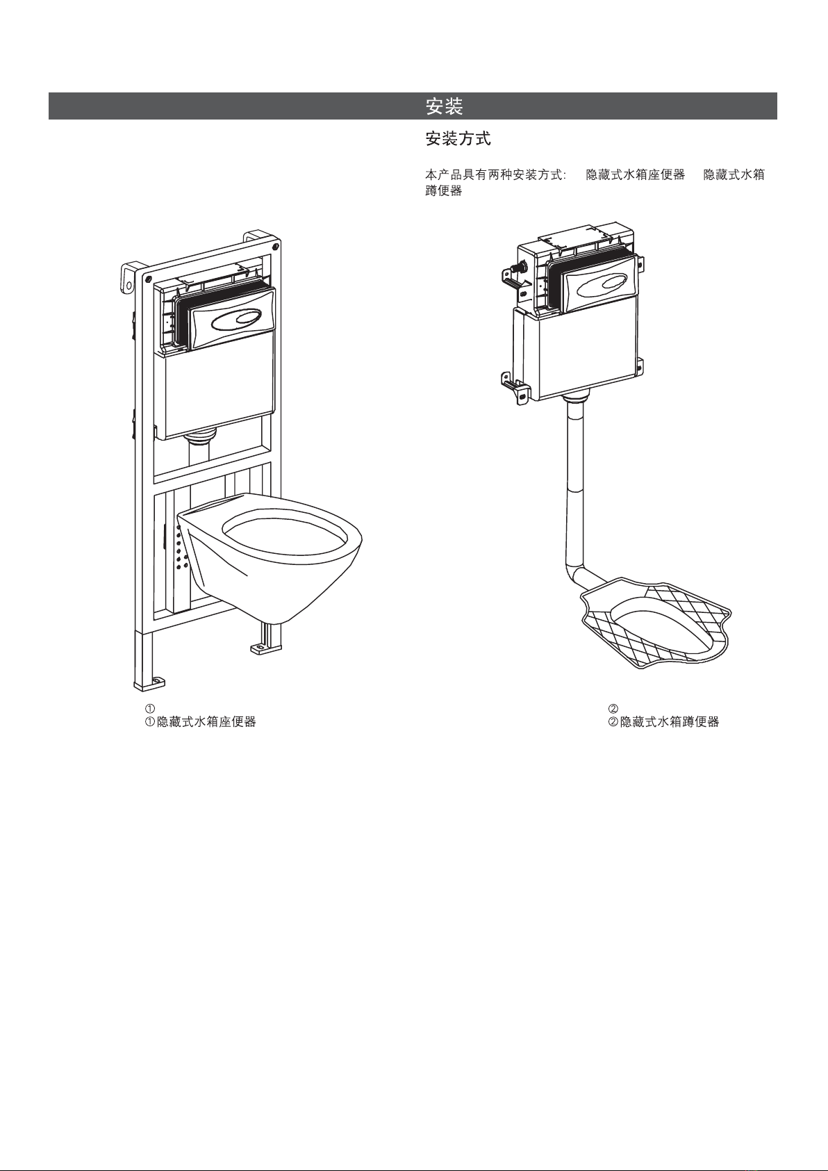
Installation of in-wall tank is much easier and nice-looking
comparative to that of traditional tank. Meanwhile, the
space layout will be more reasonable due to the
application of in-wall tank pipes and connectors.
The most remarkable advantage of in-wall tank is that the
installation will never be limited to certain area, and can
be installed wherever as you wish, which will make the
bathroom layout more reasonable and nice-looking, and
make good use of every inch of the bathroom space.
Design And Installation Concept Of In-wall Tank
, 2012
Copyright Kohler China Ltd., 2012
1048671-T01-K

-2-
05/7/13
ROUGHING-IN
UNIT: mm
Installation dimensions with iron rack
Installation dimensions without iron rack
Adhesive
Adhesive
Agglutination
UNIT: mm
478
438
230
180
1190
35
100
300
0-200
370
90
95-135
155-200 40
15-55
0-140
400 10
438
1275
348
850
196
15-55
25
OK
FFB
400kg
·
·
·
·
·
·
·
·
400
Advantages Of In-wall Tank
·
·
·
·
·
·
·
·
Sustainable to pressure of 400 kg.
Will not affect the structure of the wall and provides
excellent sound insulation.
Easy installation and time efficient.
.
.
Clean, garbage free, and space .
Made of macromolecular materials that prevents corrison
and leaking.
Adjustable dual flush design which conserves water.
Do not need to prepare any other spare parts
Easy maintenance and servicing
saving
1048671-T01-K

INSTALLATION
Ways of Installation
There are two ways of installation for the products: In-wall
tank toilet and In-wall tank squat.
In-wall Tank Squat
-3-
In-wall Tank Toilet
1048671-T01-K

Installation
A. Installation Procedures Of Toilet
1.
Tighten the bolts with medium Allen key as shown in
illustration B, and adjust the height of the adjustable
bracket according to customer's requirements.
Insert the frame screw and screw cap in the holes of fixing
frame, lock the frame screw with nut, then tighten the
frame screws on the fixing frame with medium Allen key as
shown in illustration A.
2. Drill four holes with diameter of 10mm and depth of 70mm
with churn drilling as shown, and fill in the holes with bulge
screw (knock in with hammer if necessary ) and tighten the
screw.
A.
1.
B
A
2. 10mm 70mm
()
-4-
O
Tank Frame
Nut
Adjustable Bracket
Medium Allen Key
AB
Expanding Bolt
Gasket
Expanding Bolt Cap/Bolt
/
Screw Base
Nut
Frame Screw
Screw Cap
1048671-T01-K

3. Tighten the hexagonal long screw with medium Allen key
as shown in illustration A.
Tighten the screw of adjustable brackets with medium
Allen key as shown in illustration B, and tighten the screw
with spanner.
Ensure the tank to remain level.
4. Fix the drainage cap on the fixing bracket as shown in the
illustration. Tighten the screws with medium allen key and
install the drainage cap on the drainage hole.
4.
3. A
B
Level
Hexagonal screw
Screw
Medium Allen Key
Adjustable Bracket
Screw
Loosen
Spanner
Tighten
AB
-5-
Fixing Bracket
Drainage Cap
Screw
Medium Allen Key
Drainage
Hole
1048671-T01-K

5. Install the water pipe to the connecting pipe at the side of
the tank for water supply. (
)
Inlet valves should be shut
down
5.
()
6. Install the rectangular shield in the block screen of the tank,
and tighten the screw to fix the rectangular shield to the
tank.
6. ,
7. Tighten the long screw into the holes of tank bracket, and
cover the drainage cap with big filtration cap, and the
drainage hole with small filtration cap.
7.
Rectangular
Shield
Screw
Block
Screen
-6-
Connecting
Pipe
Water Pipe
Drainage Hole
Drainage Cap
Big Filtration Cap
Small Filtration Cap
Long Screw
Tank Bracket
1048671-T01-K

8. When finishing the brickwork of the wall, take out the big
and small filtration caps, and eliminate unwanted
rectangular shield with a sharp knife.
8.
9. Install the inlet pipe and outlet pipe to the lavatory as
shown, and mark on the pipes at the back side of the tank
with a ruler and a pencil, and reserve appropriate space
according to the distance from the back of the tank to the
outlet hole on the wall.
9.
10. Eliminate unwanted part of the pipe and outlet pipe
according to the marks of reserved space, and rasp a
smooth surface with files.
inlet
10.
Rectangular Shield
Big Filtration Cap
Small Filtration Cap
Inlet Pipe
Outlet ipeP
Inlet Pipe
Reserved
Space
Outlet ipeP
-7-
1048671-T01-K

11. Install the big and small leak-proof gaskets on inlet pipe
and outlet pipe, then install it to corresponding pipes on
the toilet tank.
11. Small Leak-proof Gasket
Inlet Pipe
Outlet ipeP
Big Leak-proof Gasket
12. 48mm-58mm of the long screw shall be reserved outside
the wall as shown in the illustration. If the long screw
outside the wall is not long enough or much longer than
that needed, it should be adjusted with screwdriver or by
hand. Then apply lubricant to drainage pipe and limber
pipe to ensure a smooth installation.
12. 48mm-58mm
13. Install the Toilet as shown in the illustration, and use a
spirit level to ensure the lavatory to remain level.
13.
Long Screw
Lubricant
Spirit Level
48mm-58mm
-8-
1048671-T01-K

14.
15. When fixing the adjustable board to block screen, the
locknut should be put directly on positing of the sign of
OPEN . Remark: Stir pole shall remain level.""
15. OPEN
Long Screw
Rubber Cover
Hexagonal Nut
Decoration Cap
Gasket
Block Screen
Locknut
Adjustable Board
Stir Pole
-9-
14. Install the rubber cover gasket, hexagonal nut and
decoration cap onto long screw according to the order
shown in the illustration.
1045164 Screw Cover
1048671-T01-K

16. Fix the adjustable board on the wall by tightening the
locknut as shown in the illustration. And the locknut
should be directly put on the position of the sign of
LOCK . (Indications are marked on the adjustable board,
please refer to indications in installation)
""
16.
LOCK (
)
17. Install the cover as shown in the illustration. Put the lock
on the cover directly on the reversed lock on adjustable
board, then push the cover and lock it. The installation
shall begin from bottom to top.
17.
18. In-wall tank toilet is ready to be put into use.
18.
Lock
Adjustable Board
Reversed Lock
Cover
Adjustable Board
Locknut
Long Flush
Button Short Flush
Button
-10-
Finished Installation Illustration
1048671-T01-K

B. Fixing Squat
1. Mark on the wall for appropriate position for fixing bracket,
and drill four holes with diameter of 12mm and depth of
70-76mm with churn drilling as shown in illustration, and fill
in the holes with bulge screw and tighten the screw to set
the fixing bracket.
Note: Ensure the fixing bracket to remain level.
B.
1.
12mm 70-76mm
Screw
-11-
O
Fixing Bracket
Bulge Screw
Gasket
Spring
Nut
Put the tank onto the fixing bracket as shown in the right
figure and adjust the tank to level . Then tighten screws with
hex-head key. Note: it is a must to keep the tank level.
Connect the inlet hose with tank inlet pipe. (Note: it is
necessary to keep the inlet valve closed at this step.) ()
Level
Tank
Tighten
Loosen
Medium Allen Key
Connecting Pipe
Water Pipe
1048671-T01-K

3. Install the rectangular shield in the block screen of the tank,
and tighten the screw to fix the rectangular shield to the
tank.
3.
4. Fix the leak-proof gasket to syphon as shown in illustration,
and adjust the syphon to appropriate position to be fixed to
the infall of squat.
4.
5. When finishing the brickwork, eliminate unwanted part of
the rectangular shield.
5.
Rectangular Shield
Leak-proof Gasket
Syphon
Sharp Knife
Screw
Rectangular Shield
-12-
Block Shield
1048671-T01-K

7. Fix the adjustable board on the wall by tightening the
locknut as shown in the illustration. And the locknut should
be directly put on the position of the sign of LOCK . (Signs
are marked on the adjustable board, please refer to the
indications in installation)
""
7.
LOCK (
)
6. When fixing the adjustable board to block shield, the
locknut should be put directly on positong of the sign of
OPEN .
Remark: Stir pole shall remain level.
""
6. OPEN
Lock
Adjustable Board
Reversed Lock
Cover
Adjustable Board
Locknut
Stir Pole
Block
Shield
Locknut
Adjustable Board
8. Install the cover as shown in the illustration. Put the lock on
the cover directly on the reversed lock on adjustable board,
then push the cover and lock it. The installation shall begin
from bottom to top.
8.
-13-
1048671-T01-K

9. In-wall tank toilet is ready to be put into use.
A. Hold the cover with both hands and push upward to take
down the cover.
A.
9.
Long
Flush Button
Short Flush Button
MAINTENANCE AND CONTROL PROCEDURESMAINTENANCE AND CONTROL PROCEDURES
Finished Installation Illustration
Cover
Cover
-14-
1048671-T01-K

B. Tighten the locknut to the marked position of OPEN to
take out the adjustable board.
""
B. OPEN
Locknut
C. Pin the indentation on block screen with screwdriver to
take out the block screen.
C.
Block
Screen
D. Wash Filtration Net
Close corner valve first, then loosen and take out the
tighten nut, and wash the waste on filtration net with clean
water. Then reset the tighten nut to the original position.
D.
Open
Close Corner Valve
Tighten Nut
Filtration Net
Loosen Nut
-15-
1048671-T01-K

E.
E. Adjust The Control Pole Of Drainage Valve
Pin the pole first to take out the control button as shown in
the illustration. Then take out the fixing frame with both
hands.
Pole
Control Button
Fixing Frame
F. Pull out reversed lock on the fixing frame as shown in the
illustration, and adjust the height of the control poles to
ensure the leak-proof of drainage valve.
F.
-16-
Fixing Frame
Fixing Frame
Control Button
Pole
1048671-T01-K

H. Adjust Inlet Valve
Hoist and reduce the water level in the tank by adjusting
the control pole. Turn the control pole counterclockwise to
lower down the floating box and reduce the water level of
the tank. Turn the control pole clockwise to hoist the
floating box and increase the water level in the tank
H.
G. Adjust Drainage Valve
Drainage volume and overflow level of the tank can be
adjusted by drainage valve: 1) Heavy drainage adjustment:
Open adjustment switch to open the small hole. 2) Slight
drainage adjustment: adjust the height of floating box and
the water level of slight drainage will be at the bottom of
the floating box.
G.
(1)
(2)
Control Pole
Drainage Valve
Adjustment Switch
Floating Box
-17-
Floating Box
Adjustment Switch
1048671-T01-K

TROUBLE SHOOTING PROCEDURESTROUBLE SHOOTING PROCEDURES
No water fills in via inlet
valve
The inlet valve is closed Open inlet valve (refer to page 15)
Floating box of inlet valve is blocked by tank wall Adjust floating box to appropriate position
Floating box of inlet valve is block by waste Wash the floating box with clean water
Wrong installation of adjustable board Reset (refer to page 9)
Control pole is too long Adjust the control pole to appropriate
position
Water level of the inlet valve is not appropriate
No drainage when
pressing the heavy and
slight drainage button
Too high or too low water
level
Leak of the toilet and
squat
Symptoms Probable Causes Recommended Action
Control pole is too short
Inappropriate adjustment of the overflow pipe
Toilet swing Hexagonal nut is loose
(15)
(9)
(16)
(9)
Readjust water level (refer to page 16)
Adjust the control pole to appropriate
position
Adjust the overflow pipe to appropriate
position
Tighten the hexagonal nut (refer to page 9)
-18-
1048671-T01-K
This manual suits for next models
5
Table of contents
Other Kohler Water Heater manuals
Popular Water Heater manuals by other brands

Timberk
Timberk SWH RS1 30 V instruction manual

Toyotomi
Toyotomi OM-128HH installation manual

EDA
EDA Recup Eco 310L manual

STIEBEL ELTRON
STIEBEL ELTRON DHM 3 Installation

CTC Union
CTC Union EcoZenith I 550 Installation and maintenance manual

gledhill
gledhill StainlessLite HP180IND Design, installation & servicing instructions

Worcester
Worcester GREENSPRING CWi47 Installation and operating instructions

Bradford White
Bradford White M-1-20L6DS specification

Airxcel
Airxcel Aqua-Hot Reporter 400 Series installation manual

TLV
TLV SteamAqua SQ10 instruction manual

Graf
Graf CARAT XL Installation and maintenance instructions

Whale
Whale iVan quick start guide