Table of Contents
4
4
4
5
5
6
8
9
9
10
11
22
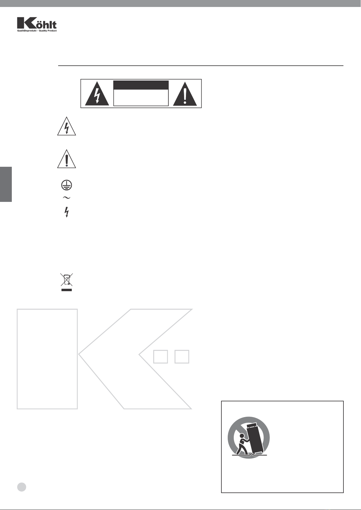
Important Safety Symbols
This symbol, wherever used, alerts you to the
presence of un-insulated and dangerous voltages
within the product enclosure. These are voltages that
may be sufficient to constitute the risk of electric shock
or death.
This symbol, wherever used, alerts you to important
operating and maintenance instructions. Please read.
Protective Ground Terminal
AC mains (Alternating Current)
AC mains (Alternating Current)
Denotes the product is turned on.
Denotes the product is turned off.
WARNING
Describes precautions that should be observed to
prevent the possibility of death or injury to the user.
CAUTION
Describes precautions that should be observed to
prevent damage to the product.
Disposing of this product should not be placed in
municipal waste but rather in a separate collection.
WARNING
Power Supply
Ensure that them a inssource voltage (AC outlet)
matches the voltage rating of the product. Failure to do
so could result in damage to the product and
possibly the user. Unplug the product before electrical
storms occur and when unused for long periods of time
to reduce the risk of electric shock or fire.
External Connection
Always use proper ready-made insulated mains
cabling (power cord). Failure to do so could result in
shock/death or fire. If in doubt, seek advice from a
registered electrician.
Do Not Remove Any Covers
Within the product are areas where high voltages may
present. To reduce the risk of electric shock do not
remove any covers unless the AC mains power cord is
removed. Covers should be removed by qualified
service personnel only.
No user serviceable parts inside.
Fuse
To prevent fire and damage to the product, use only the
recommended fuse type as indicated in this manual.
Do not short-circuit the fuse holder. Before replacing
the fuse, make sure that the product is OFF and
disconnected from the AC outlet.
ON:
OFF:
PORTABLE CART WARNING
Carts and stands - The
component should be
used only with a cart or
stan d th at i s r ecom-
m e n d e d b y t h e
manufacturer.
A component and cart
combination should be
moved with care. Quick stops, excessive force,
and u n e v e n surfaces may c a u s e t h e
component and cart combination to overturn.
Protective Ground
Before turning the unit ON, make sure that it is
connected to Ground. This is to prevent the risk of
electric shock.
Never cut internal or external Ground wires. Like wise,
never remove Ground wiring from the Protective
Ground Terminal.
Operating Conditions
Always install in accordance with the manufacturer's
instructions.
To avoid the risk of electric shock and damage, do not
subject this product to any liquid/rain or moisture.
Do not use this product when in close proximity to
water.
Do not install this product near any direct heat source.
Do not block areas of ventilation. Failure to do so could
result in fire.
Keep product away from naked flames.
IMPORTANT SAFETY INSTRUCTIONS
- Read these instructions
- Follow all instructions
- Keep these instructions. Do not discard.
- Heed all warnings.
- Only use attachments / accessories specified by the
manufacturer.
Power Cord and Plug
Do not tamper with the power cord or plug. These are
designed for your safety.
Do not remove Ground connections!
If the plug does not fit your AC out let seek advice
from a qualified electrician.
Protect the power cord and plug from any physical
stress to avoid risk of electric shock.
Do not place heavy objects on the power cord. This
could cause electric shock or fire.
Cleaning
When required, either blow off dust from the product
or use a dry cloth.
Do not use any solvents such as Benzol or Alcohol.
For safety, keep product clean and free from dust.
Servicing
Refer all servicing to qualified service personnel only.
Do not perform any servicing other than those
instructions contained within the User's Manual.
32
Do not open -
risk of electric shock
CAUTION
ENG
ENG
1. INTRODUCTION
2. INSTALLATION TIPS
3. USEFULL DATA
4. QUICK START
5. CONNECT MANNER
6. BACK PANEL DESCRIPTION
7. CONNECTION PLATE SYSTEM
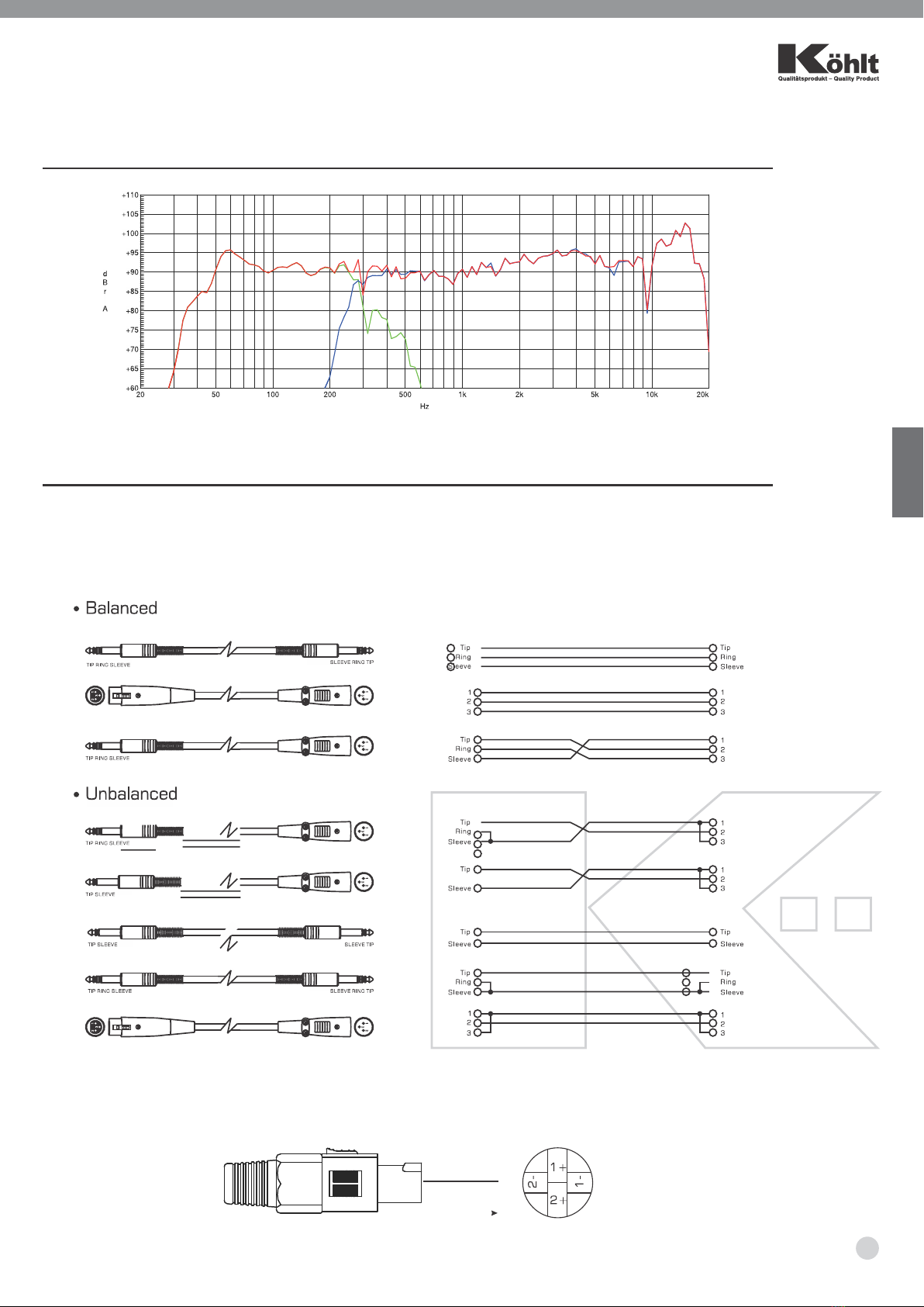
8. FREQUENCY RESPONSE DIAGRAM
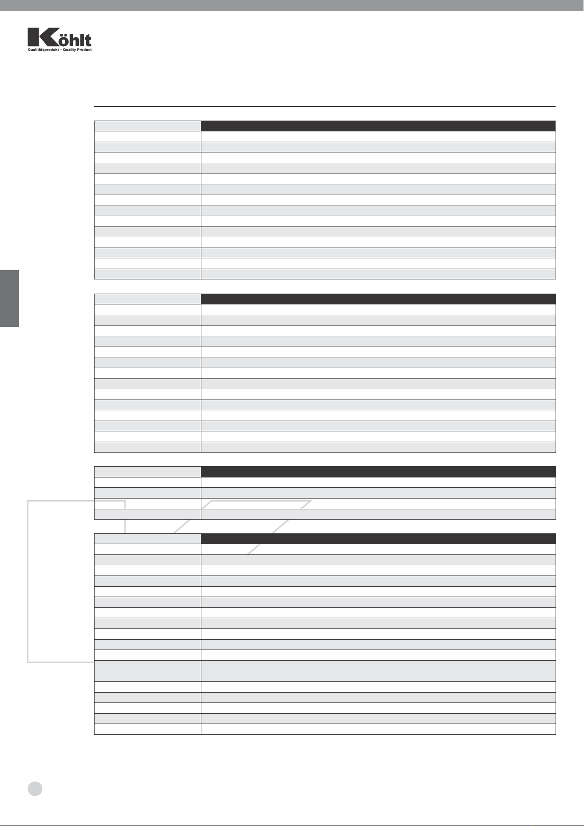
9. WIRE CONNECTIONS
10. TECHNICAL SPECIFICATIONS
11. DSP SOFTWARE CONNECTION INSTRUCTIONS
12. NOTES