Koki Holdings CJ 90VST2 User manual

PRODUCT NAME
90 mm (3-1/2”) Jig Saw
Model
CJ 90VST2
REPAIR GUIDE ---------------------------------------------------------------------------------------------------------------- 1
1. Precautions on disassembly and reassembly ----------------------------------------------------------- 1
• Disassembly -------------------------------------------------------------------------------------------------- 1
• Reassembly -------------------------------------------------------------------------------------------------- 5
• Application of lubricant ------------------------------------------------------------------------------------- 6
• Tightening torque ------------------------------------------------------------------------------------------- 6
• Checking for insulating distance ------------------------------------------------------------------------ 7
• Insulation test ------------------------------------------------------------------------------------------------ 7
• No-load current ---------------------------------------------------------------------------------------------- 7
• Wiring diagram ---------------------------------------------------------------------------------------------- 7
CONTENTS
C
CONFIDENTIAL
Oct. 2020
Overseas Sales Management Dept.

-1-
• Removal of the base and lever
[1]
[19]
[20]
[21]
[22]
[59]
[55]
[64]
[65]
WARNING: Be sure to turn off the power switch and disconnect the power cord plug from the wall
outlet before conducting repair. Be sure to remove the blade to prevent damage to its
cutting edge or personal injury due to the blade.
1. Precautions on disassembly and reassembly
[Bold] numbers in the description below correspond to the item numbers in the parts list and exploded
assembly diagram for the Model CJ 90VST2.
1. Removal of the base and lever
Loosen the Hex. Socket Hd. Bolt M5 x 18 [65] and remove the Base [55] together with the Base Locker [64]
from the Gear Holder Ass’y [59]. Loosen the Tapping Screw (W/Flange) D3 x 20 [22] and remove the
Washer [21], Lever [20], and Lever Spring [19] from Housing (A).(B) Set [1].
Disassembly
REPAIR GUIDE

-2-
• Disassembly of housing (A).(B) set
2. Disassembly of housing (A).(B) set
(1) Loosen two Tapping Screws (W/Flange) D4 x 20 (Black) [17] and remove the Grip Cover [15] from
Housing (A). (B) Set [1].
(2) Loosen seven Tapping Screws (W/Flange) D4 x 20 (Black) [17] and remove housing (B) (the name plate
is attached) of Housing (A). (B) Set [1].
NOTE: Remove the Cord Armor [8] side to facilitate removal of housing (B).
(3) Loosen two Tapping Screws (W/Flange) D4 x 16 [10] and remove the Cord [14] together with the Cord
Clip [9]. Remove the Gear Holder Ass’y [59], Stator Ass’y [27], Trigger Switch [4], Controller [11], Guard
Bar [18], Brush Holder [25], and Carbon Brush [26] from Housing (A). (B) Set [1]. Then housing (A) can
be removed.
NOTE: • Be careful that the Carbon Brush [26] may pop out at disassembly.
• If it is difficult to remove the Gear Holder Ass’y [59], mount the Base [55] to the Gear
Holder Ass’y [59] and raise the Base [55] to remove the Gear Holder Ass’y [59].
[1]
[10]
[8]
[14]
[25]
[59]
[24]
[24]
[26]
[27]
[23]
[9]
[15]
[18]
[11]
[4]
[25]
[10]
[26]
[14]

-3-
• Removal of the plunger ass’y and blade holder ass’y
[29]
[30]
[31]
[32]
[33]
[34]
[35]
[36]
[37]
[38]
[39]
[40]
[41]
[42]
[43]
[44]
3. Disassembly of the plunger ass’y and blade holder ass’y
(1) Pull out the D6 Pin [58] from the Gear Holder Ass’y [59] and remove Plunger Holder (A) [43] from the
plunger ass’y.
(2) Remove two Seal Lock Hex. Socket Hd. Bolts M3 x 6 [30] and remove the Plunger Cover [29]. Then
remove Plunger (A) [44].
(3) Remove Plunger Holder (B) [33] (including the Spring Plate [32] and Spring (C) [31]), Packing [34], and
Washer (A) [35] from Plunger (B) [37]. Remove Spring (C) [31] from Plunger Holder (B) [33] and turn
the Spring Plate [32] by 90° to remove it.
(4) Remove the Retaining Ring D15 [36] from Plunger (B) [37] and pull the Holder Cover [42] down to
remove it. Pull out the Holder Spring [41] carefully not to deform it by holding the position inserted in
Plunger (B) [37] with pliers.
NOTE: Be careful that the Plunger Piece [40] may be pushed out of Plunger (B) [37] by the force
of Spring (C) [39].

-4-
• Removal of the gear holder ass’y, armature ass’y, and change knob
[45]
[46]
[47]
[48]
[49]
[50]
[35]
[58]
[59]
[24]
[52]
[53]
[39]
[51]
[54]
[60]
[61]
[23]
4. Removal of the gear holder ass’y, armature ass’y, and change knob
(1) Pull out Connecting Piece (A) [45] and Needle Bearing [46] from the Gear [48].
(2) Remove the Retaining Ring for D7 Shaft [47] at the tip of the spindle.
(3) Remove the Gear [48], Balance Weight [49], Orbital Cam [50], and Washer (A) [35] in this order.
(4) Pull out the press-fitted Armature Ass’y [23] (including the Ball Bearing 608VV [24]) from the Gear Holder
Ass'y [59].
(5) Remove the Retaining Ring (E-Type) for D5 Shaft [51]. Remove the Change Knob [54], Spring (C) [39],
and Steel Ball 5/32 [53].
NOTE: Be careful not to lose Spring (C) [39] and Steel Ball 5/32 [53].
(6) Remove the Needle Roller D4 x 24 [52] from the Gear Holder Ass'y [59]. Then remove the Roller Holder
[61] and Needle Roller [60].

-5-
• Mounting the change knob
Perform reassembly by reversing the disassembly procedure. However, special attention should be given
to the following items.
1. Mounting the change knob
Mount Spring (C) [39] and Steel Ball 5/32 [53] in the Change
Knob [54] according to the following steps.
(1) Apply Nippeco SEP-3A grease to the Steel Ball 5/32 [53]
and then place it into the groove.
(2) Put Spring (C) [39] in the Change Knob [54]. While
pushing the Steel Ball 5/32 [53] with Spring (C) [39], mount
the Retaining Ring (E-Type) for D5 Shaft [51].
(3) Check the Change Knob [54] for any abnormality by
moving it.
2. Reassembly of the plunger ass’y
(1) Put the Spring Plate [32] in Plunger Holder (B) [33]. Then
mount Spring (C) [31].
(2) Mount the Retaining Ring D15 [36], Washer (A) [35],
Packing [34], and Plunger Holder (B) [33] to Plunger (B)
[37] in this order.
(3) Pressing the concave portion of Plunger (B) [37] against
the portion under the slotted hole on Plunger (A) [44], fit
the D3 pins on the Plunger Cover [29] in the holes on
Plunger (A) [44] and fix it by tightening two Seal Lock Hex.
Socket Hd. Bolts M3 x 6 [30].
(4) Fit the tip of the Plunger Piece [40] in Spring (C) [39] and
put Needle Roller (C) [38] in Spring (C) [39]. Insert the
Plunger Piece [40] into Plunger (B) [37] aligning the U-
shape protrusion on the Plunger Piece [40] with the U-
shape groove on Plunger (B) [37].
(5) Insert the inner tip of the Holder Spring [41] in the 1 mm
diameter hole on Plunger (B) [37] while pressing the
Plunger Piece [40]. At this time, check that the Plunger
Piece [40] is securely retained by the Holder Spring [41].
(6) Match the outer tip of the Holder Spring [41] with the
groove on the Holder Cover [42]. Turn the Holder Cover
[42] by about 90° to insert it into Plunger (B) [37]. At this
time, check that the groove on the Holder Cover [42] is
positioned over the flange of Plunger (B) [37].
(7) Fit the Retaining Ring D15 [36] in the groove of the Holder
Cover [42].
Reassembly
[39]
[53]
[54]
[51]
• Reassembly of the plunger ass’y
[29]
[30]
[32]
[31]
[33]
[34]
[36]
[35]
[37]
[39]
[38]
[44]
[43]
[41]
[40]
[42]

-6-
3. Reassembly of housing (A).(B) set, gear holder, and plunger ass’y
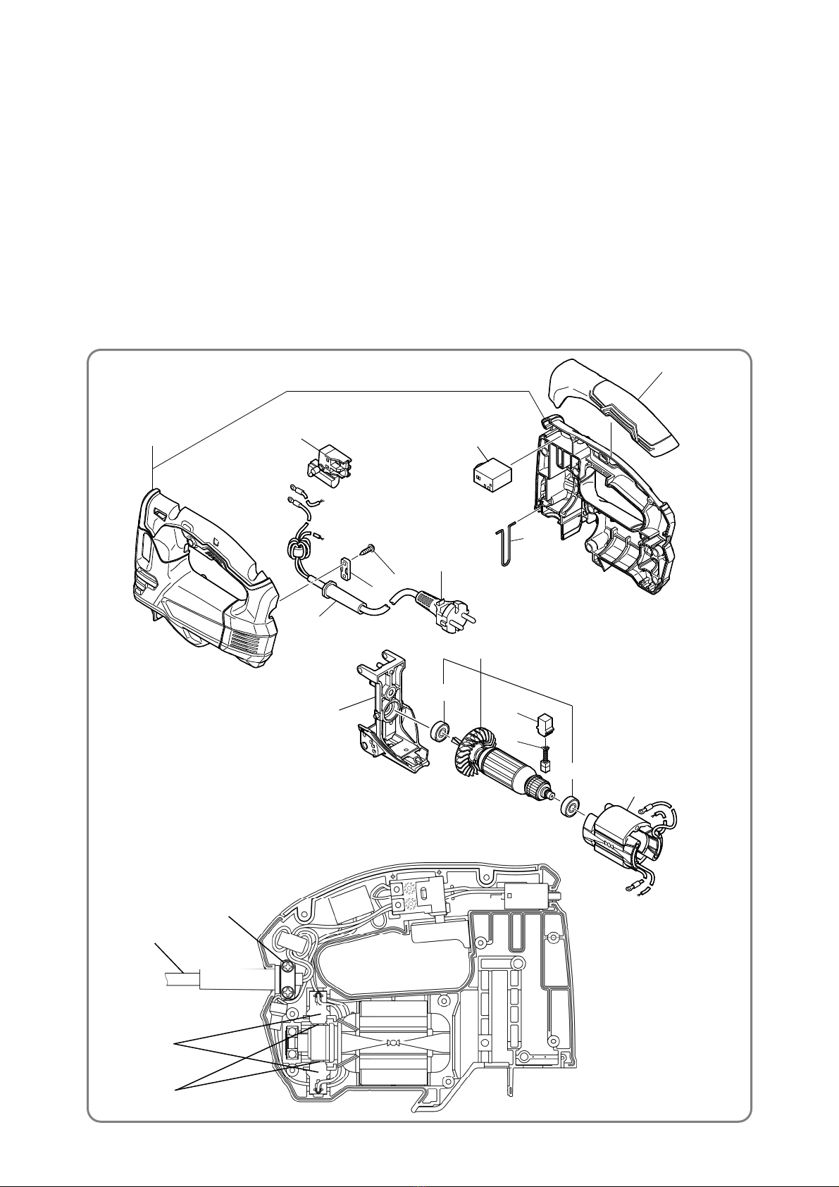
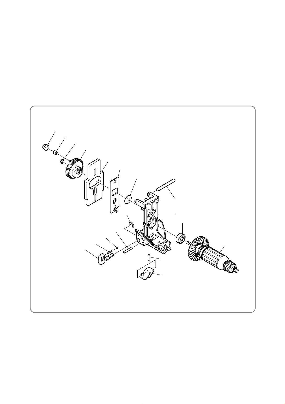
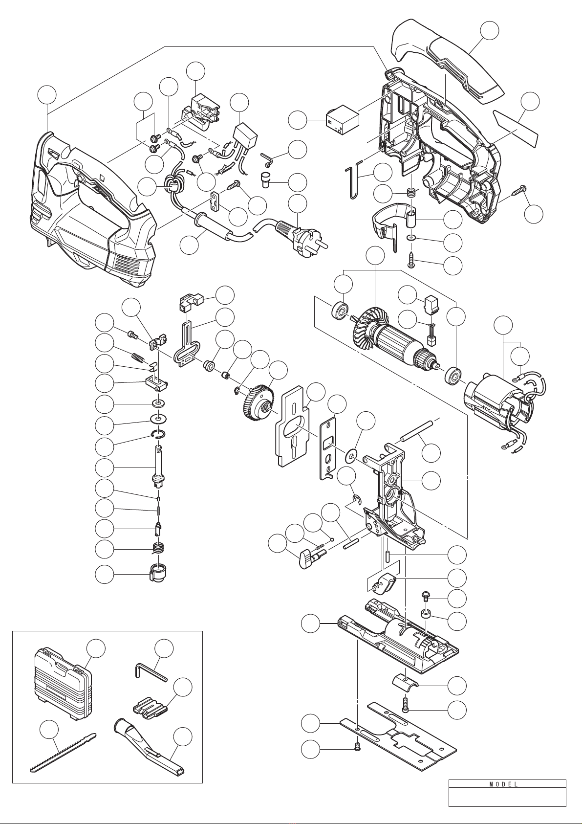
(1) Mount the parts from Armature Ass’y [23] through the plunger ass’y to the Gear Holder Ass’y [59]. Insert
the Armature Ass’y [23] into the Stator Ass’y [27]. At this time, face the shear droop side of the Balance
Weight [49] to the Orbital Cam [50]. Mount the new Retaining Ring for D7 Shaft [47] facing its shear
droop side to the Gear [48]. At this time, check that the Retaining Ring for D7 Shaft [47] is properly fitted
in the spindle groove.
NOTE: • Do not reuse the Retaining Ring for D7 Shaft [47].
• Be careful not to open the Retaining Ring for D7 Shaft [47] excessively when mounting.
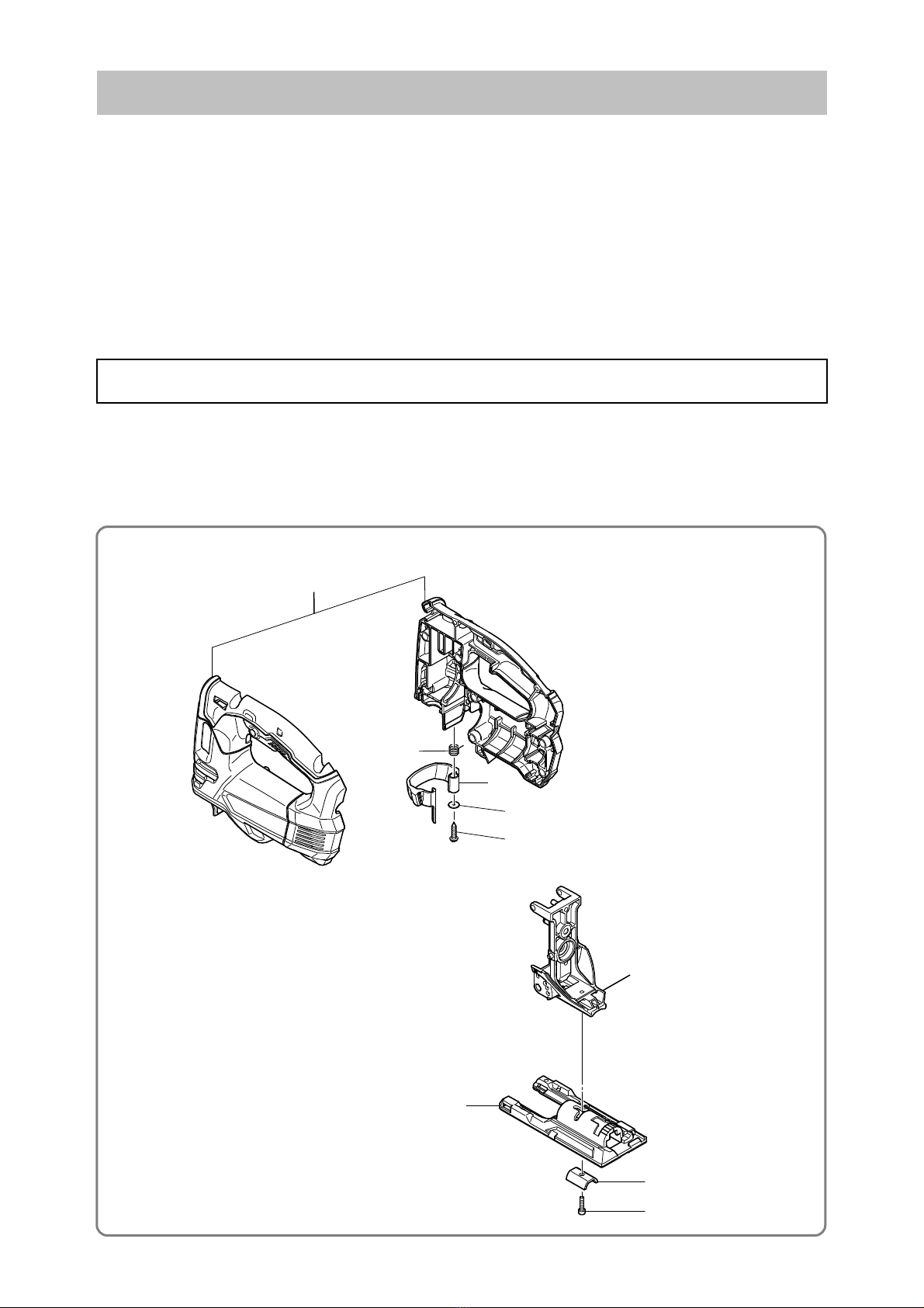
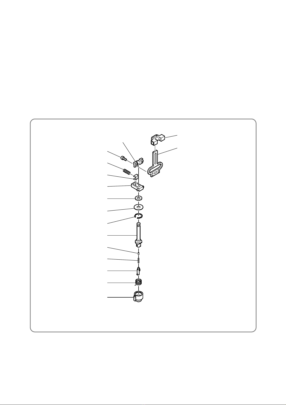
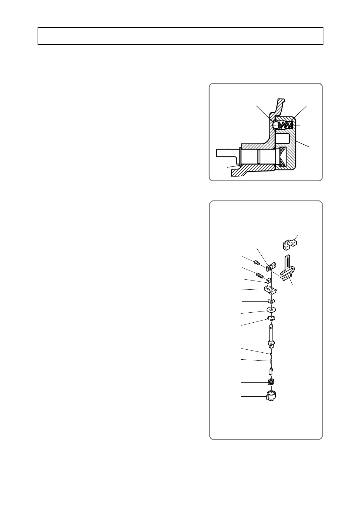
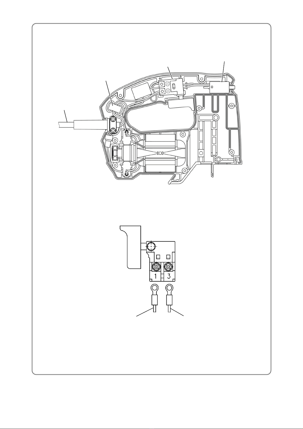
(2) Fit the protrusions of Plunger Holder (B) [33] in the holes of Housing (A).(B) Set [1]. At this time, check
that Washer (A) [35] and Packing [34] are mounted between Housing (A).(B) Set [1] and Plunger Holder
(B) [33].
(3) Fit the protrusions of the Gear Holder Ass’y [59] in the holes of Housing (A).(B) Set [1].
(4) Fit the D6 Pin [58] in the holes of Housing (A).(B) Set [1] to fix the mechanical unit to Housing (A).(B)
Set [1].
Apply specified amount of grease to the following portions.
Nippeco SEP-3A grease
• Entire circumference of the Gear [48], particularly its teeth
• Both sides of Washer (A) [35]
• Both sides of the Orbital Cam [50]
• Both sides of the Balance Weight [49]
• Outer circumference of Connecting Piece (A) [45]
• Tooth flank of the Armature Ass’y [23]
• Outer circumference of the Steel Ball 5/32 [53]
• Entire circumference of Plunger (A) [44]
• Sliding portion of the Roller Holder [61] and the Needle Roller D4 x 24 [52]
Molub-Alloy No. 777-1 grease
• Inner diameter portion of the gear ass’y (needle bearing: 1.0 g)
• Inner circumferences of Connecting Piece (A) [45] and Needle Bearing [46] (0.5 g)
• Holes of the Orbital Cam [50]
• Holes of the Balance Weight [49]
• Sliding portion of the gear ass’y and the Balance Weight [49]
Nippeco BC-4 grease
• Cylindrical portion (7 mm in dia.) of Plunger (B) [37] (1.0 g)
• Tapping Screw (W/Flange) D4 [10][17] --------------------------------------- 1.96±0.49 N•m (20±5 kgf•cm)
• Tapping Screw (W/Flange) D3 x 20 [22] -------------------------------------- 0.88± 0.1 N•m (9±1 kgf•cm)
• Seal Lock Hex. Socket Hd. Bolt M3 x 6 [30]--------------------------------- 1.47± 0.29 N•m (15±3 kgf•cm)
• Hex. Socket Hd. Bolt M5 x 18 [65] --------------------------------------------- 4.90±0.49 N•m (50±5 kgf•cm)
• Special Bolt [57] -------------------------------------------------------------------- 2.76±0.29 N•m (28±3 kgf•cm)
• Machine Screw (W/Washer) M4 x 5 [62] ------------------------------------- 1.76±0.29 N•m (18±3 kgf•cm)
• Machine Screw (W/Washer) M3.5 x 6 [2] ------------------------------------ 0.6±0.15 N•m (6±1.5 kgf•cm)
Application of lubricant
Tightening torque

-7-
• Connecting diagram
Trigger Switch [4]
Controller [11]
Connector 50092 [13] Cable Tie [12]
Black or blue Black
Stator
Stator
Ar
Blue
Blue
Gray
Red
White or brown
Ferrite Core [7]
Noise suppressor
NOTE: The Ferrite Core [7] and the noise suppressor are provided only for the
Model CJ 90VST2 destined for the U.K., Europe, Russia, South Africa,
Turkey, Australia, and New Zealand.
Do not strip the coating excessively at the connected portion of each internal wire.
Be careful not to get the internal wires caught between housings (A) and (B) of Housing (A).(B) Set [1].
On completion of disassembly and repair, measure the insulation resistance and dielectric strength.
Insulation resistance: 7 MΩor higher with a 500 VDC megohm tester
Dielectric strength: 2,500 VAC/minute, with no abnormalities
After no-load operation for 30 minutes, the no-load current value should be as specified below at a frequency
of 50/60 Hz.
Voltage 100 V 110 V 120 V 220 V 230 V 240 V
Current max. 2.9 to 4.3 A 2.6 to 4.0 A 2.4 to 3.6 A 1.2 to 1.8 A 1.3 to 1.9 A 1.4 to 2.0 A
Carefully ensure that wiring is accomplished as illustrated below, as incorrect wiring will result in inadequate
or reverse rotation.
Wiring diagram
Insulation test
Checking for insulating distance
No-load current

-8-
• Wiring diagram
Cord [14]
Ferrite Core [7]
Trigger Switch [4]
Controller [11]
Cord (white or brown)
Controller (red)

A
Rev.1
CJ90VST2
A
501
502
503
504
505
1
2
2
3
4
6
8
9
10
5
11
12
13
14
18
15
16
17
19
20
21
22
24
23
25
26 24
27
28
30
31
32
33
34
35
36
37
29
43
44
45
46
47
48
49
50
51
52
53
54
55
56
57
58
59
60
61
62
63
64
65
7
35
39
39
40
41
42
38

ITEM CODE NO.
NO. NO. USED
*1 376483 HOUSING (A).(B) SET 1
*1 376483M HOUSING (A).(B) SET 1 FOR USA, CAN
2 305499 MACHINE SCREW (W/WASHER) M3.5 X 6 2
*3 376462 INTERNAL WIRE ASS'Y (B) 1 FOR UAE, THA, SIN, MAL, HKG
4 376485 TRIGGER SWITCH 1
*5 376461 INTERNAL WIRE ASS'Y (A) 1 FOR EUROPE, GBR, AUS, NAL, SAF, RUS, TUR,
USA, CAN, IND
6 980063 TERMINAL 1
*7 334379 FERRITE CORE 1 FOR EUROPE, GBR, AUS, NAL, SAF, RUS, TUR,
USA, CAN, IND
8 930487 CORD ARMOR D8.2 1
9 937631 CORD CLIP 1
10 984750 TAPPING SCREW (W/FLANGE) D4 X 16 2
*11 376488 CONTROLLER 1 FOR 110 V-120 V
*11 337760 CONTROLLER 1 FOR 220 V-240 V
12 975144 CABLE TIE 1
13 959141 CONNECTOR 50092 (10 PCS.) 1
*14 500234Z CORD 1 (CORD ARMOR D8.2) FOR EUROPE
*14 500409Z CORD 1
(
CORD
ARMOR
D8.2
)
FOR
SIN
,
SAF
,
RUS
,
TUR
,
IND
*14 500505Z CORD 1 (CORD ARMOR D8.2) FOR GBR (230 V), UAE,
HKG, MAL
*14 500461Z CORD 1
(CORD ARMOR D8.2) FOR GBR (110 V), UAE (110 V)
*14 500439Z CORD 1 (CORD ARMOR D8.2) FOR AUS, NZL
*14 500240Z CORD 1 (CORD ARMOR D8.2) FOR USA, CAN
*14 500468Z CORD 1 (CORD ARMOR D8.2) FOR THA
15 376482 GRIP COVER 1
16 NAME PLATE 1
17 301653 TAPPING SCREW (W/FLANGE) D4 X 20 (BLACK) 9
18 376484 GUARD BAR 1
19 376481 LEVER SPRING 1
20 375856 LEVER 1
21 333916 WASHER 1
22 332929 TAPPING SCREW (W/FLANGE) D3 X 20 1
*23 361136C ARMATURE ASS'Y 110 V 1 INCLUD. 24
*23 361136D ARMATURE ASS'Y 120 V 1 INCLUD. 24
*23 361136E ARMATURE ASS'Y 220 V-240 V 1 INCLUD. 24
24 608VVM BALL BEARING 608VVC2PS2L 2
25 930483 BRUSH HOLDER 2
26 999041 CARBON BRUSH (1 PAIR) 2
*27 341075C STATOR ASS'Y 110 V 1 INCLUD. 28
*27 341075D STATOR ASS'Y 120 V 1 INCLUD. 28
*27 341075E STATOR ASS'Y 220 V-240 V 1 INCLUD. 28
28 960356 TERMINAL (A) M3.5 (10 PCS.) 2
29 376473 PLUNGER COVER 1
30 325077 SEAL LOCK HEX. SOCKET HD. BOLT M3 X 6 2
31 376476 SPRING (C) 1
32 376475 SPRING PLATE 1
33 376487 PLUNGER HOLDER (B) 1
34 376474 PACKING 1
35 376467 WASHER (A) 2
36 376480 RETAINING RING D15 1
37 376472 PLUNGER (B) 1
38 376604 NEEDLE ROLLER (C) 1
39 982454 SPRING (C) 2
40 376479 PLUNGER PIECE 1
41 376478 HOLDER SPRING 1
42 376477 HOLDER COVER 1
43 376470 PLUNGER HOLDER (A) 1
44 376471 PLUNGER (A) 1
45 332829 CONNECTING PIECE (A) 1
46 325242 NEEDLE BEARING 1
47 994251 RETAINING RING FOR D7 SHAFT 1
48 376466 GEAR 1
49 376469 BALANCE WEIGHT 1
50 376468 ORBITAL CAM 1
51 673489 RETAINING RING (E-TYPE) FOR D5 SHAFT 1
52 376683 NEEDLE ROLLER D4 X 24 1
53 335297 STEEL BALL 5/32 (10 PCS.) 1
54 338992 CHANGE KNOB 1
55 375854 BASE 1
56 375855 BASE PLATE 1
57 321996 SPECIAL BOLT 4
58 376460 D6 PIN 1
DESCRIPTION REMARKS

ITEM CODE NO.
NO. NO. USED
DESCRIPTION REMARKS
59 376464 GEAR HOLDER ASS'Y 1 INCLUD. 39, 51-54, 60, 61
60 983545 NEEDLE ROLLER 1
61 376465 ROLLER HOLDER 1
62 375857 MACHINE SCREW (W/WASHER) M4 X 5 1
63 321576 RUBBER BUSHING 1
64 339663 BASE LOCKER 1
65 372724 HEX. SOCKET HD. BOLT M5 X 18 1
*501 337883 CASE 1 EXCEPT FOR USA, CAN
502 879357 JIG SAW BLADES NO. 41 (5 PCS.) 1
503 944458 HEX. BAR WRENCH 4 MM 1
504 338997 SPLINTER GUARD 1
*505 370492 DUST COLLECTOR 1 FOR EUROPE, GBR, SAF, RUS, TUR
601 321593 GUIDE 1
602 339018 SUB BASE 1
603 370492 DUST COLLECTOR 1
604 930035 GREASE (SEP-3A) (100 G) 1
605 372814 GREASE (NIPPECO BC-4) 75 G 1
606 325149 GREASE (MOLUB-ALLOY NO. 777-1) 75 G 1
607 879336 JIG SAW BLADES NO. 11 (5 PCS.) 1
608 879337 JIG SAW BLADES NO. 12 (5 PCS.) 1
609 879338 JIG SAW BLADES NO. 15 (5 PCS.) 1
610 879339 JIG SAW BLADES NO. 16 (5 PCS.) 1
611 879340 JIG SAW BLADES NO. 21 (5 PCS.) 1
612 879341 JIG SAW BLADES NO. 22 (5 PCS.) 1
613 963400 JIG SAW BLADES NO. 97 FOR STAINLESS (5 PCS.) 1
OPTIONAL ACCESSORIES
STANDARD ACCESSORIES
Table of contents