Kolpak Walk-In User manual

www.kolpak.com 800-225-9916 1
Kolpak
Walk-In
Installation & Operation
Manual
Kolpak
2915 Tennessee Avenue North
Parsons, TN 38363
Phone: 800-225-9916
500000400-10
September 2017

www.kolpak.com 800-225-9916 2
Table of Contents
General Safety Information .............................................................................................3
Receiving Inspection.......................................................................................................4
Panel Count ....................................................................................................................4
Panel Storage ..............................................................................................................4-5
Panel Identification..........................................................................................................5
Site Preparation ...........................................................................................................6-7
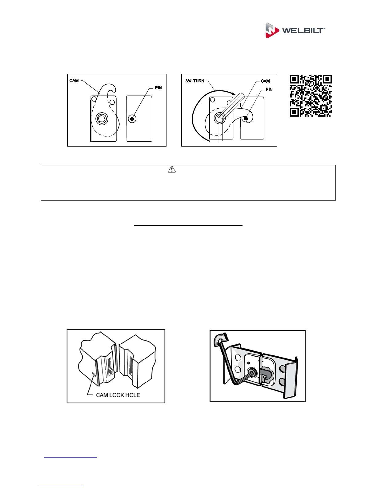
Cam Action Panel Fasteners........................................................................................7-8
General Installation Guidelines .......................................................................................8
Screed Identification & Installation.............................................................................9-11
Floor Panel Installation.............................................................................................12-13
Floor Overlay Installation...............................................................................................14
Concrete & Tile Flooring................................................................................................ 15
Wall Panel & Door Section Installation.....................................................................15-16
Ceiling Panel Installation...............................................................................................16
Split-Over Partition Wall/Ceiling .................................................................................... 17
Ceiling Support.............................................................................................................. 18
Interior/Exterior Ramps ................................................................................................. 19
Plug Buttons & Penetrations .........................................................................................20
Trim & Wainscoting Material .........................................................................................21
Threshold Installation....................................................................................................22
Door Sweep Adjustment................................................................................................23
Adjustable Hinges......................................................................................................... 24
Thermometer Testing & Recalibration........................................................................... 25
Electrical Connections................................................................................................... 26
Tapered Roof System ...................................................................................................27
Membrane Roof System...........................................................................................28-31
Maintenance & Housekeeping ......................................................................................32
System Start-up Checklist........................................................................................33-36
Warranty Information..................................................................................................... 37

www.kolpak.com 800-225-9916 3
General Safety Information
Read this manual carefully before beginning the installation and operation of the unit.
Scan the QR Code below to view the Basic Walk-In Installation Service Video.
Special attention is required to all sections identified with the following warning and
caution notices:
WARNING
Text in a Warning box alerts you to a potential personal injury situation. Read each
Warning statement before proceeding and work carefully.
CAUTION
Text in a Caution box alerts you to a situation in which you could damage the unit. Read
each Caution statement before proceeding and work carefully.
Disregarding these special notices may result in personal injury and/or damage to the
unit.
Safety Notices:
Installation and maintenance/servicing are to be performed only by trained and
qualified personnel familiar with commercial walk-in products.
Ensure that all field wiring conforms to the equipment requirements and all
applicable local and national codes.
Disconnect all power sources before servicing the unit.
Sheet metal and coil surfaces have sharp edges. Use appropriate protective
gloves to prevent injury.
Use appropriate eye protection during installation and servicing.

www.kolpak.com 800-225-9916 4
Receiving Inspection
Check the shipment carefully and compare to the bill of lading. Account for all items
listed and inspect each container for damage. Carefully inspect for any concealed
damage. Report any shortages or damages to the carrier, note on the bill of lading, and
file a freight claim.
Damaged material cannot be returned to the manufacturer without prior approval. A
Return Material Authorization (RMA) must be obtained. Contact a sales representative
at 800-826-7036.
Panel Count and Hardware
Using the packing list and skid documentation, count the wall panels, corners, ceilings,
doors, and floors where applicable. Locate and verify the accessory and hardware
package(s).
WARNING
Do not attempt to lift the panels or accessories by yourself. Always have adequate
lifting equipment or manpower available to accomplish the task safely.
Do not unwrap the skids and leave the panels in a position that they could fall over or
blow over and cause an injury. Be sure that panels are adequately restrained at all
times.
CAUTION
Acids and oils on hands and fingers could discolor wall panel finish. Make sure to wear
appropriate gloves that are free from residue while handling wall and ceiling panels.
CAUTION
Make sure to store the panels as noted below if necessary to ensure that they are not
damaged prior to being installed.
Panel Storage
If the walk-in panels must be stored on a job site before installation, store them inside if
possible.
The PVC protective panel covering should only be removed after final assembly of the
walk-in. Gloves should be worn to prevent acids and oils on hands/fingers from creating
smudges on panel surface.
The panels may be stored on skids as received, provided the skids are on level surface
and kept free of moisture.

www.kolpak.com 800-225-9916 5
If the panels must be stored outside, store them on edge with the grooved side (female
rail) facing down. Kiln-dried wood spacers provide a ventilation gap to prevent moisture
stains from forming on the panels’ metal skins. Cover the panels with black plastic to
keep out sunlight and moisture. Be sure the plastic does not touch the ground, allowing
air circulation.
Panel identification
Each panel is labeled to aid in identification and proper placement. Panel item numbers
are referenced on the product assembly drawing showing proper location for intended
installation within the unit.

www.kolpak.com 800-225-9916 6
Site Preparation
CAUTION
Ensure that the area for installation is level and clear of all debris before beginning
assembly. If care is not taken to assure a level base, wall and ceiling panels will not
align properly, causing problems in installation and operation of door panels, and
potential performance issues due to escessive air leaks. The two recommended
techniques to level the floor area are self-leveling epoxy and/or asphalt shingles.
For concrete slabs, above grade is recommended. A slab below grade is not permitted.
A 2” minimum clearance is required between the unit and any adjacent structures to
allow for wall surface irregularities and for air circulation. Air circulation around the
walk-in of 5 CFM per 100 Sq. Ft. of wall area is recommended. Failure to allow for this
clearance and air flow may result in performance issues such as excesive moisture
and/or condensation in the unit or adjoining areas.
Using the supplied assembly drawing (in hardware box), mark the perimeter of
screed, wall, or floor sections on the existing building floor using a chalk line.
Perimeter lines must be square and parallel. Use the 3, 4, 5 rule of squaring.
After the first two lines, measure and establish the rest of the perimeter.

www.kolpak.com 800-225-9916 7
If the installation area is not level, find the high point of this perimeter line. The
floor, floor screed and wall must be leveled to this point.
Use a 4’ level to determine floor levelness. Be sure to check both directions for
floor levelness.
Cam Action Panel Fasteners
Before starting to assemble the unit, be sure to familiarize yourself with the operation of
the panel fasteners.
To operate the cam locks, insert a 5/16” hex wrench (packed in hardware box)
through the access hole in the panel interior skin, and into the hex opening in the
fastener. Turn the wrench clockwise approximately 3/4 of a turn to put the cam
hook into the locked position.
If a problem should occur, such as having to unlock a panel that was not properly
positioned, you must turn the handle counterclockwise until it stops, in order to
reset the cam position.

www.kolpak.com 800-225-9916 8
Scan the QR Code below to view Operating The Cam Lock Service Video.
CAUTION
Using a hammer to drive the hex wrench into the panel fastener can result in damaging
the interface surface, rendering the lock unusable. Clear the hole of any debris if the
wrench cannot be fully inserted with normal hand pressure.
General Installation Guidelines
All insulated panels have a tongue and a groove perimeter edge. This interlocking
design and the panel edge gaskets will result in an air-tight walk-in when installed
square and level. Refer to the assembly drawing for the general layout and specific
panel placement and markings.
The tongue side of the panel and cam lock holes is on the left of each seam when
viewed from the interior of the walk-in (standing on the inside and looking out). The
exact location of the tongue (M) and groove (F) for ceiling and floor panels, if required,
will be shown on the assembly drawing.

www.kolpak.com 800-225-9916 9
Screed Identification And Installation
There are many styles of screeds used in floorless walk-in coolers and freezers. The
types of screeds furnished with your unit will be identified on the unit assembly drawing.
Breaker strips (thermal breaks) are used to prevent heat transfer between the
cooled side and the ambient side of a concrete floor. Without these thermal
barriers, heat transfer through the concrete layer is relatively rapid, causing a
greater likelihood of condensation and icing outside of the unit, as well as
increased energy consumption and cooling load on the refrigeration system.
CAUTION
When having a product installed with a thermal break, make sure that the contractor
leaves the top of the thermal break exposed for later inspection, not covered by
concrete. If there are performance issues after installation, it may be necessary to
inspect the position and condition of the thermal break.
Standard screeds are available in both vinyl (with integral floor coves) and metal
versions. Vinyl screeds cannot be used in outdoor applications due to potential
issues with UV degradation caused by sunlight. Most thermal breaks are
installed to be level with the concrete surface. Heights for vinyl screeds are 1.5”
or 4”, while metal screeds are available in various heights as necessary for the
application. Standard screeds are pre-cut with intended installation locations
shown on the assembly drawing.

www.kolpak.com 800-225-9916 10
U-shaped screeds are available for customers who desire to use a vinyl screed,
but need either a lower profile or need a special height finished unit, and would
prefer to use a standard sized wall panels. U-shaped screeds are factory cut to
length and mitered on the corners, with intended installation locations shown on
the assembly drawing.
Flat-bottom walls are available for configurations that require a metal screed, do
not have an integral cove, and will be anchored by an exterior (or interior)
mounting angle. Mounting angles are supplied in 10’ lengths and field cut to fit
the dimensions of the enclosure as necessary.
Screed Installation
Place the screeds on the floor using the chalk lines as guides. Where factory cut
screed is used, screed sizes and layout are identified in the assembly drawings.

www.kolpak.com 800-225-9916 11
A thermal break (breaker strip) is required to separate all freezer interior concrete
from the exterior concrete. The interior freezer concrete floor must be insulated
and completely isolated. The screed/wall is to be centered over the thermal
break.
Apply two beads of non-drying butyl sealant to the bottom side of the screeds.
Start at back corner and fasten screeds in place for two adjoining walls. Fasten
screed as shown on assembly drawing with fasteners provided.
Each section of screed is to have a minimum of two fasteners, one on each end.
This is especially true for screed sections under the door. For long screed
sections, fasteners should be spaced at a maximum of four feet.
To insure proper fit, do not fasten screeds for remaining walls until the first two
walls are assembled.
CAUTION
Thermal breaks are required in freezer applications and recommended in cooler
applications to separate the interior flooring from the exterior floor. Thermal breaks
prevent heat transfer and increase energy efficiency.
A 3/8” bead of non-drying butyl sealant is required and should be continuous around the
complete perimeter of the walk-in. This sealant application will assist in maintaining the
vapor barrier.

www.kolpak.com 800-225-9916 12
Floor Panel Installation
Review the floor panel layout on the assembly drawing.

www.kolpak.com 800-225-9916 13
Panels are labeled with numbers corresponding to those on the assembly drawing.
CAUTION
Stationary floor loads of up to 1000 pounds per square foot can be stored on Welbilt
standard floor panels and up to 5000 pounds per square foot can be stored on Welbilt
structural floor panels. If forklift trucks are used, special construction techniques must
be followed for concrete wear surfaces over the panels. Consult customer service for
recommendations.
Mark and level the floor according to site preparation requirements.
Lay out floor panels in correct sequence according to assembly drawings,
making sure the flooring is level.
Lock floor panels together, making sure edges are flush and square.

www.kolpak.com 800-225-9916 14
Flooring Overlay Installation
CAUTION
Installation of overlay material is best accomplished before the refrigeration system has
been started, and before any product has been loaded. In the event that overlay must
be added at a later date, ensure that the refrigeration system has been turned off and
that the subsurface has been allowed to return to a normal working temperature.
Installing at a low temperature may not allow the adhesive/sealant to cure adequately.
Clean and dry subsurface.
Apply silicone to the underside of flooring overlay material.
Begin laying first row of flooring overlay ½” away from the edge of the floor
according to the drawing and secure to the subsurface with sheet metals screws
or anchors.
All sheets must be as flush as possible to one another.
All sheets must be secured using a sheet metal screws or anchors every 24”.
Ensure that at least one fastener is used near each corner of the overlay
material.
Continue to follow the layout according to the drawing until all sheets are flush
and secured to the subsurface.
Caulk all seams and edges of flooring overlay material.
Allow 1-3 hours for the adhesive/sealant to dry prior to resuming use of the walk-
in.

www.kolpak.com 800-225-9916 15
Concrete & Tile Flooring
CAUTION
Gasses emitted by curing concrete floors or tile grout will damage panel finishes.
Adequate ventilation must be provided when the concrete floor or tile setting bed and
grout is curing. Leave all doors open for ventilation. If concrete or tile is to be installed
after walk-in is erected, protect the wall finish by applying a protective covering.
Wall Panels & Door Section Installation
Review the wall panel and door sections layout on the assembly drawing. Panels are
labeled with numbers corresponding to those on the assembly drawing.
Start with a back corner and work around the unit both ways, ending with a front
corner.Do not lock the walls into the floor/screed at this time.
Begin wall panel assembly by cam-locking a back corner panel and one wall
panel together. See assembly drawing for correct panel placement, and tongue
and groove directions.
Door sections will be installed in sequence along with wall panels. Use a level to
set the door section plumb and level.

www.kolpak.com 800-225-9916 16
Work around unit in both directions, ending at opposite corner.
Ensure the edges and tops of walls are flush.
Lock the wall panels and door section into the floor/screed.
Ceiling Panel Installation
Review the ceiling panel layout on the assembly drawing. Panels are labeled with
numbers corresponding to those on the assembly drawing.
Use assembly drawings for correct panel placement and sequence.
Begin with an end section for a single compartment enclosure, or a tee panel for
a multi-compartment enclosure
Place ceiling panels in position, per the assembly drawings, on top of wall
panels. Do not lock ceiling panels to the wall at this time.
Check panel alignment.
Cam-lock ceiling panels together.
After several ceiling panels are in position and locked together, check all wall to
ceiling joints for flush fit and proper alignment.
Lock ceiling panels to wall panels.

www.kolpak.com 800-225-9916 17
WARNING
The top panels on walk-in units are designed, at a minimum, for an allowable live load
of ten pounds per square foot as noted on submittal drawings and installation
instructions. Top panels are not designed as work platforms or for dry storage and
should not be used as such. Use in such a manner could damage the structural
integrity of the top panels and will void the manufacturer’s warranty. Do not place
condensing units on top of ceiling panels.
Split-Over Partition Wall Ceiling Installation
Indoor applications:Apply a continuous 3/8” bead of non-drying (butyl) sealant
to the both sides of the wall to ceiling joint. Lock ceiling panels together and
align over partition wall. Once all ceiling panels are assembled and aligned, lock
the wall to the ceiling.
Outdoor applications: Apply butyl tape to the partition wall anchor plate. Lock
ceiling panels together and align over partition wall. Once all ceilings are assembled
and aligned, attach lag bolts through the ceiling cam lock hole into the anchor plate.
3/8”LAG BOLTS THROUGH
MALE CAM LOCK HOLES
PARTITION WALL
ANCHOR
PLATE
CEILING
PANELS
BUTYL
REFRIGERATION
TAPE (SHIPPED
LOOSE)

www.kolpak.com 800-225-9916 18
CAUTION
Apply a continuous 3/8” bead of non-drying (butyl) sealant at all partition wall/ceiling
joints. Apply the sealant on both sides of the panel. This sealant application will assist
in maintaining the vapor barrier.
Ceiling Support
Indoor enclosures with dimensions of more than 14’-8” in both length and width must
have some type of support for the ceiling panels. Suspended ceiling hangers, foamed
in super ceiling channel, exterior self-support steel beams, or interior steel beams with
column supports must be used. Reference details provided on the as built drawing and
the diagram below for suspended ceiling support installation instructions.
WARNING
These systems must be installed properly in order to provide the necessary support for
the ceiling panels, allowing them to maintain their design load rating. Failure to do so
may result in an unsatisfactory installation, or an unsafe condition.

www.kolpak.com 800-225-9916 19
Interior Ramps Installation
Review the floor panel layout on the assembly drawing. Panels are labeled with
numbers corresponding to those on the assembly drawing.
Apply sealant at ramp cavity to concrete and floor intersections. Install ramp and
drive fasteners in place. Apply sealant to all ramp edges.
Exterior Ramp Installation
Install the exterior ramp and fasteners per the details provided on the assembly
drawing.

www.kolpak.com 800-225-9916 20
Plug Button Installation
Remove protective covering from panels, if applied.
Check that all cam locks are engaged.
Insert plug buttons into the cam lock wrench access holes and firmly tap in place
using a rubber mallet.
Plug buttons supplied for walls and ceilings are vinyl, plug buttons supplied for
floors are either stainless steel or high-strength plastic
Penetrations
Some areas of walk-in panels contain working parts and should not be
penetrated. Do not make a penetration within 2” of cam lock holes or panel
seams.
Penetrations must be completely sealed (insulation, foam, etc.) to prevent heat
transfer and condensation/ice formation. Electrical penetrations must be sealed
both internally and externally to form an acceptable seal.
Penetrations is outdoor ceilings is not permitted.
Trim and Wainscoting Material Installation
Table of contents