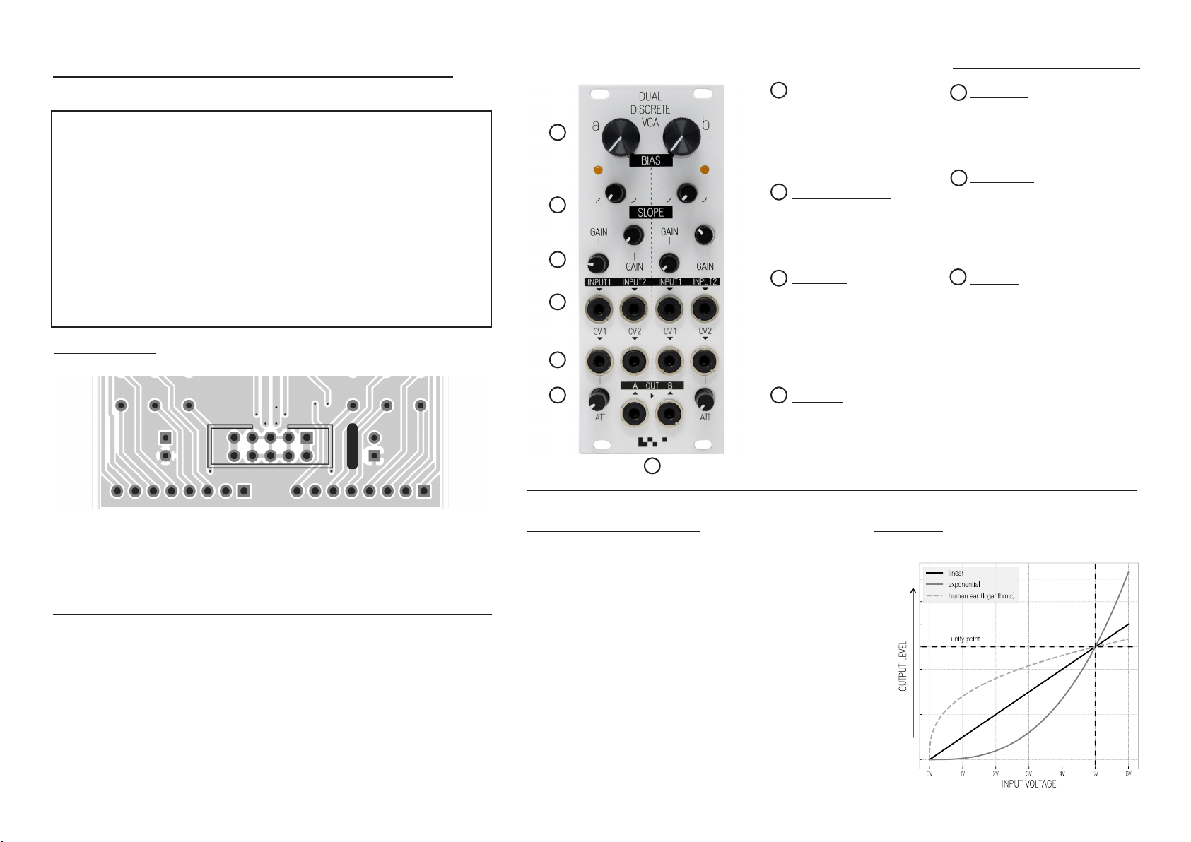
GAIN (A+B)
Pre-gain for input signal. Al-
lows overdriving the input
stage (saturation / distortion).
SLOPE (A+B)
VCA response shape from
linear / to exponential.
Fully CCW = linear. Fully
CW = exponential.
ATT (A+B)
Attenuator for CV 1 input on
channel A and CV 2 input
on channel B. Attenuates the
voltage of the incoming CV
signal. Unipolar.
KOMA Elektronik GmbH
Weisestr. 24
12049 Berlin
Germany
Questions? Need help?
Please contact us at:
support@koma-elektronik.com
Dear User,
ank you for purchasing our Dual Discrete VCA!
e KOMA Dual Discrete VCA oers two independent high quality VCA
channels, both built up out of discrete transistor cells with low CV and au-
dio bleed, very low noise and distortion. e VCA’s feature set also enables
you to experiment with the linear/exponential response curve, changing the
dynamics of your sound. Play around with the gain settings for creative dis-
tortion eects in the classic KOMA style:
High quality sound by default, noise by choice!
1
2
3
4
5
SLOPE CONTROL AND ATTENUATION
e SLOPE control enables you to seamlessly shi be-
tween a linear and exponential curve. Our VCA is de-
signed to operate with CV signals of 0V - 5V.
When using a 5V CV signal, the extreme settings of the
SLOPE control translate to the same perceived loudness,
see ‘unity point’ in the graph CV Response on the right.
We added attenuators (ATT) on CV Input 1 of Channel
A and CV Input 2 of Channel B, to allow the user to
adjust the incoming CV level. For instance: when you
have a higher CV signal, you can attenuate it down to
the appropriate 5V level.
INPUT 1-2 (A+B)
Input to VCA. Designed
primarily for audio sig-
nals. 100k Impedance.
AC coupled
CV INPUT 1-2 (A+B)
CV control for VCA Vol-
ume, 100k Impedance.
DC coupled.
BIAS (A+B)
Manual control of VCA
volume. e value of the
BIAS control is mixed to-
gether with the incoming
CV signal.
OUT (A+B)
Output from VCA, 1k
impedance. AC coupled.
FEATURES AND FUNCTIONS
6
7
KOMA ELEKTRONIK - DUAL DISCRETE VCA
USER MANUAL
CV RESPONSE
POWER CONNECTION
A close up of the Power Connector on the back side of the module.
Always make sure you align the red stripe on the power connector to the
white stripe marker on the module.
Made with love in Berlin, Germany.
7
1
2
3
4
6
5


