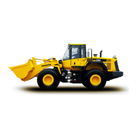
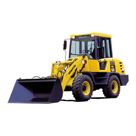
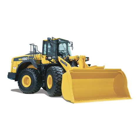
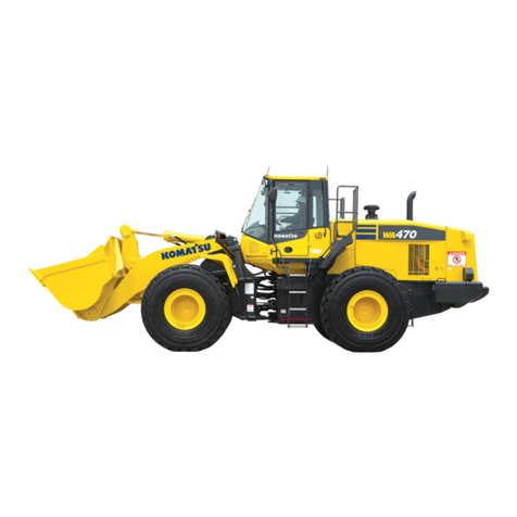
Komatsu AVANCE LOADER WA700-3 User manual

NOTICE
Komatsu has Operation & Maintenance Manuals written in
some other languages. If a foreign language manual is
necessary, contact your local distributor for availability.
Unsafe use of this machine may cause serious injury
or death. Operators and maintenance personnel
must read this manual before operating or maintain-
ing this machine. This manual should be kept near the
machine for reference and periodically reviewed
by all personnel who will come into contact with it.
WA700-3
WHEEL LOADER
SERIAL NUMBERS
WA700-50010
and up
SEAM018501

0-1
1. FOREWORD
This manual provides rules and guidelines which will help you use this machine safely and
effectively. Keep this manual handy and have all personnel read it periodically. If this manual has been
lost or has become dirty and can not be read, request a replacement manual from Komatsu or your
Komatsu distributor.
If you sell the machine, be sure to give this manual to the new owners.
Continuing improvements in the design of this machine can lead to changes in detail which may not
be reflected in this manual. Consult Komatsu or your Komatsu distributor for the latest available
information of your machine or for questions regarding information in this manual.
This manual may contain attachments and optional equipment that are not available in your area.
Consult Komatsu or your Komatsu distributor for those items you may require.
WARNING
‡ Improper operation and maintenance of this machine can be hazardous and could result in serious
injury or death.
‡ Operators and maintenance personnel should read this manual thoroughly before beginning
operation or maintenance.
‡ Some actions involved in operation and maintenance of the machine can cause a serious accident,
if they are not done in a manner described in this manual.
‡ The procedures and precautions given in this manual apply only to intended uses of the machine.
If you use your machine for any unintended uses that are not specifically prohibited, you must
be sure that it is safe for you and others. In no event should you or others engage in prohibited
uses or actions as described in this manual.
‡ Komatsu delivers machines that comply with all applicable regulations and standards of the
country to which it has been shipped. If this machine has been purchased in another country or
purchased from someone in another country, it may lack certain safety devices and specifications
that are necessary for use in your country. If there is any question about whether your product
complies with the applicable standards and regulations of your country, consult Komatsu or your
Komatsu distributor before operating the machine.
‡ The description of safety is given in SAFETY INFORMATION on page 0-2 and in SAFETY from page
1-1.
CALIFORNIA
Proposition 65 Warning
Diesel engine exhaust and some of its
constituents are known to the State
of California to cause cancer, birth
defects, and other reproductive
harm.

0-2
2. SAFETY INFORMATION
Most accidents are caused by the failure to follow fundamental safety rules for the operation and
maintenance of machines. To avoid accidents, read, understand and follow all precautions and warnings
in this manual and on the machine before performing operation and maintenance.
To identify safety messages in this manual and on machine labels, the following signal words are
used.
DANGER – This word is used on safety messages and safety labels where there is a high
probability of serious injury or death if the hazard is not avoided. These safety
messages or labels usually describe precautions that must be taken to avoid the
hazard. Failure to avoid this hazard may also result in serious damage to the
machine.
WARNING – This word is used on safety messages and safety labels where there is a
potentially dangerous situation which could result in serious injury or death if
the hazard is not avoided. These safety messages or labels usually describe
precautions that must be taken to avoid the hazard. Failure to avoid this hazard
may also result in serious damage to the machine.
CAUTION – This word is used on safety messages and safety labels for hazards which could
result in minor or moderate injury if the hazard is not avoided. This word might
also be word for hazards where the only result could be damage to the machine.
NOTICE – This word is used for precautions that must be taken to avoid actions which
could shorten the life of the machine.
Safety precautions are described in SAFETY from page 1-1.
Komatsu cannot predict every circumstance that might involve a potential hazard in operation and
maintenance. Therefore the safety messages in this manual and on the machine may not include all
possible safety precautions. If any procedures or actions not specifically recommended or allowed in this
manual are used, you must be sure that you and others can do such procedures and actions safely and
without damaging the machine. If you are unsure about the safety of some procedures, contact your
Komatsu distributor.

0-3
3. INTRODUCTION
3.1 INTENDED USE
This machine is intended mainly for the following operations.
‡ Digging operations
‡ Leveling operations
‡ Pushing operations
‡ Loading operations
For details of the operating procedure, see “12.10 WORK POSSIBLE USING WHEEL LOADER”.
3.2 FEATURES
1. Easy to operate work equipment
‡ By using the kick-down switch installed to the knob on the boom control lever, it is possible to
shift down from 2nd to 1st, thereby providing speedy digging and loading operations.
‡ Installing the bucket corner teeth and segment edge greatly increases the wear resistance of the
bucket.
2. Easy to operate machine
‡ The electrical transmission control provides light gear shifting, enabling finger control.
‡ The length of both the directional and speed levers can be adjusted individually.
‡ The PPC valve (proportional pressure type) provides good response when raising the boom and
little operating force is required.
‡ A wrist rest is provided by the control levers to improve the ease of control.
3. Operating comfort
‡ The cab is provided with a door-open lock, large sun visor, and small storage box. It also has
rubber mounts to further reduce the vibration and noise.
‡ The sealed pressurized cab with air conditioner make pleasant operations possible.
‡ A fabric seat is used for the operator’s seat to give the operator a good ride.
4. High levels of safety
‡ Safety is ensured by the good visibility from the cab, the wide area around the operator’s seat,
steps for getting on and off the machine, and the walk-through floor at the rear of the cab.
‡ Checks before starting and checks for abnormalities during operation can be carried out using
the machine monitor.
‡ Maintenance free wet-type multiple disc brakes are used.
3.3 BREAKING IN THE MACHINE
Your Komatsu machine has been thoroughly adjusted and tested before shipment.
However, operating the machine under severe conditions at the beginning can adversely affect the
performance and shorten the machine life.
Be sure to break in the machine for the initial 100 hours (as indicated by the service meter.)
During breaking in:
‡ Idle the engine for 5 minutes after starting it up.
‡ Avoid operation with heavy loads or at high speeds.
‡ Avoid sudden starts, sudden acceleration, sudden steering and sudden stops except in cases of
emergency.
The precautions given in this manual for operating, maintenance, and safety procedures are only
those that apply when this product is used for the specified purpose. If the machine is used for a purpose
that is not listed in this manual, Komatsu cannot bear any responsibility for safety. All consideration of
safety in such operations is the responsibility of the user.
Operations that are prohibited in this manual must never be carried out under any circumstances.

0-4
4. LOCATION OF PLATES, TABLE TO ENTER
SERIAL NO. AND DISTRIBUTOR
REMARKS
Machine serial No.:
Engine serial No.:
Distributor name:
Address: Phone:
Service personnel for your machine:
Position of stamp
This is stamped on the center of the front frame on the right side
of the machine.
4.2 ENGINE SERIAL NO. PLATE POSITION
Position of plate
On the left of the cylinder block, when seen from the fan side.
Position of stamp
This is stamped on the left side of the engine cylinder block as
seen from the fan.
4.1 MACHINE SERIAL NO. PLATE POSITION
Position of plate
On the center right of the front frame.
4.3 TABLE TO ENTER SERIAL NO. AND DISTRIBUTOR

0-5
5. CONTENTS
1. Foreword ............................................................................................................................................ 0- 1
2. Safety information ............................................................................................................................ 0- 2
3. Introduction ........................................................................................................................................ 0- 3
4. Location of plates, table to enter serial No. and distributor ...................................................... 0- 4
SAFETY
6. General precautions .......................................................................................................................... 1- 2
7. Precautions during operation .......................................................................................................... 1- 7
7.1 Before starting engine ............................................................................................................ 1- 7
7.2 After starting engine ............................................................................................................... 1-10
7.3 Transportation .......................................................................................................................... 1-18
7.4 Battery ....................................................................................................................................... 1-19
7.5 Towing ...................................................................................................................................... 1-21
8. Precautions for maintenance ........................................................................................................... 1-22
8.1 Before carrying out maintenance .......................................................................................... 1-22
8.2 During maintenance ................................................................................................................ 1-27
8.3 Tires .......................................................................................................................................... 1-33
9. Position for attaching safety labels ................................................................................................ 1-35
OPERATION
10. General view ...................................................................................................................................... 2- 2
10.1 General view of machine ....................................................................................................... 2- 2
10.2 General view of controls and gauges .................................................................................. 2- 3
11. Explanation of components ............................................................................................................. 2- 4
11.1 Machine monitor ..................................................................................................................... 2- 4
11.2 Switches ................................................................................................................................... 2-14
11.3 Control levers, pedals ............................................................................................................. 2-23
11.4 Steering column tilt lever ....................................................................................................... 2-28
11.5 Cap with lock ........................................................................................................................... 2-28
11.6 Engine emergency stop switch and fuel stop lever ........................................................... 2-29
11.7 Safety bar ................................................................................................................................. 2-29
11.8 Towing pin ............................................................................................................................... 2-30
11.9 Grease pump ........................................................................................................................... 2-31
11.10 Backup alarm ........................................................................................................................... 2-31
11.11 Door-open lock ........................................................................................................................ 2-31
11.12 Tool box ................................................................................................................................... 2-31
11.13 Fuse ........................................................................................................................................... 2-32
11.14 Slow-blow fuse ........................................................................................................................ 2-33
11.15 Lunch box tray ......................................................................................................................... 2-34
11.16 Storaging place of this manual ............................................................................................. 2-34
11.17 Taking off power ..................................................................................................................... 2-34
11.18 AM/FM car radio ...................................................................................................................... 2-35
11.19 AM/FM radio-cassette stereo ................................................................................................. 2-39
11.20 Car heater ................................................................................................................................. 2-48
11.21 Air conditioner ......................................................................................................................... 2-50
11.22 Precautions when handling accumulator ............................................................................. 2-53

0-6
5. CONTENTS
12. Operation ............................................................................................................................................ 2-54
12.1 Check before starting engine ................................................................................................. 2-54
12.2 Starting engine ........................................................................................................................ 2-68
12.3 Operations and checks after starting engine ....................................................................... 2-74
12.4 Moving machine off ................................................................................................................ 2-75
12.5 Changing gear speed .............................................................................................................. 2-77
12.6 Changing direction .................................................................................................................. 2-78
12.7 Turning ..................................................................................................................................... 2-78
12.8 Stopping machine ................................................................................................................... 2-79
12.9 Operation of work equipment ............................................................................................... 2-80
12.10 Work possible using wheel loader ........................................................................................ 2-81
12.11 Precautions for operation ....................................................................................................... 2-86
12.12 Adjusting work equipment posture ...................................................................................... 2-88
12.13 Parking machine ...................................................................................................................... 2-90
12.14 Checks after completion of operation .................................................................................. 2-91
12.15 Stopping engine ...................................................................................................................... 2-91
12.16 Check after stopping engine .................................................................................................. 2-92
12.17 Locking ...................................................................................................................................... 2-92
12.18 Handling the tires .................................................................................................................... 2-93
12.19 Removal and installation of the bucket ................................................................................ 2-95
13. Transportation ................................................................................................................................... 2-99
13.1 Lifting machine ........................................................................................................................ 2-99
14. Cold weather operation ................................................................................................................... 2-100
14.1 Precautions for low temperature ........................................................................................... 2-100
14.2 Precautions after completion of work .................................................................................. 2-102
14.3 After cold weather ................................................................................................................... 2-102
14.4 Warming-up operation for steering hydraulic circuit in cold weather ............................. 2-103
15. Long-term storage ............................................................................................................................ 2-104
15.1 Before storage ......................................................................................................................... 2-104
15.2 During storage ......................................................................................................................... 2-104
15.3 After storage ............................................................................................................................ 2-104
16. Troubleshooting ................................................................................................................................ 2-105
16.1 When machine runs out of fuel ............................................................................................ 2-105
16.2 Towing the machine ............................................................................................................... 2-106
16.3 If battery is discharged ........................................................................................................... 2-109
16.4 Other trouble ............................................................................................................................ 2-113

0-7
5. CONTENTS
MAINTENANCE
17. Guides to maintenance .................................................................................................................... 3- 2
18. Outlines of service ............................................................................................................................ 3- 5
18.1 Outline of oil, fuel, coolant .................................................................................................... 3- 5
18.2 Outline of electric system ...................................................................................................... 3- 8
19. Wear parts list ................................................................................................................................... 3- 9
20. Use of fuel, coolant and lubricants according to ambient temperature ................................... 3-10
21. Standard tightening torques for bolts and nuts .......................................................................... 3-14
21.1 Introduction of necessary tools ............................................................................................. 3-14
21.2 Torque list ................................................................................................................................ 3-15
22. Periodic replacement of safety critical parts ................................................................................. 3-16
23. Maintenance schedule chart ............................................................................................................ 3-18
23.1 Maintenance schedule chart .................................................................................................. 3-18
24. Service Procedure ............................................................................................................................. 3-22
24.1 Initial 250 hours service ......................................................................................................... 3-22
24.2 When required ......................................................................................................................... 3-23
24.3 Check before starting .............................................................................................................. 3-45
24.4 Every 50 hours service ........................................................................................................... 3-52
24.5 Every 100 hours service ......................................................................................................... 3-53

24.6 Every 250 hours service ......................................................................................................... 3-57
24.7 Every 500 hours service ......................................................................................................... 3-63

24.8 Every 1000 hours service ....................................................................................................... 3-68
24.9 Every 2000 hours service ....................................................................................................... 3-74
24.10 Every 4000 hours service ....................................................................................................... 3-83
SPECIFICATIONS
25. Specifications ..................................................................................................................................... 4- 2
OPTIONS, ATTACHMENTS
26. Optional part and attachments ....................................................................................................... 5- 2
27. Selecting buckets and tires ............................................................................................................. 5- 3
28. Handling auto shift system ............................................................................................................. 5- 4
28.1 Automatic shift system ........................................................................................................... 5- 4
28.2 Precautions when changing direction .................................................................................. 5- 5
29. Handling joystick steering system .................................................................................................. 5- 6
29.1 Explanation of components ...................................................................................................5-6
29.2 Structure and function of joystick steering .......................................................................... 5- 7
29.3 Operation method of joystick steering system ................................................................... 5-10
29.4 Precautions for steering with joystick .................................................................................. 5-12
29.5 Adjustment of joystick console ............................................................................................. 5-13
29.6 Adjustment operator’s seat .................................................................................................... 5-14

0-8
5. CONTENTS
30. Main monitor failure display ............................................................................................................ 5-16
30.1 Main monitor failure display ................................................................................................. 5-16
30.2 Error codes list indicated on main monitor ......................................................................... 5-17
31. Handling auto-greasing system ....................................................................................................... 5-19
31.1 Method of operating auto-greasing system......................................................................... 5-20
31.2 Precautions when handling auto-greasing system ............................................................. 5-20
31.3 Method of adjusting discharge from injector ...................................................................... 5-26
31.4 Method of setting timer ......................................................................................................... 5-27

1-1
SAFETY
WARNING
Read and follow all safety precautions. Failure to do so may result
in serious injury or death.
This safety section also contains precautions for optional equip-
ment and attachments.

1-2
WARNING: For reasons of safety, always
follow these safety precautions.
SAFETY FEATURES
‡ Be sure all guards and covers are installed in their proper position. Have guards and covers
repaired immediately if damaged.
Proper position ➞See “12.1.1 WALK-AROUND CHECK”
‡ Use safety features such as safety lock lever 1and seat belts properly.
‡ NEVER remove any safety features. ALWAYS keep them in good operating condition.
Safety lock lever ➞See “12.13 PARKING MACHINE”
Seat belts ➞See “12.1.3 ADJUSTMENT BEFORE OPERATION”
‡ Improper use of safety features could result in serious bodily injury or death.
CLOTHING AND PERSONAL PROTECTIVE ITEMS
‡ Avoid loose clothing, jewelry, and loose long hair. They can catch on controls or in moving parts
and cause serious injury or death.
‡ Also, do not wear oily clothes, because they are flammable.
‡ Wear a hard hat, safety glasses, safety shoes, mask or gloves when operating or maintaining the
machine. Always wear safety goggles, hard hat and heavy gloves if your job involves scattering
metal chips or minute materials particularly when driving pins with a hammer and when cleaning
the air cleaner element with compressed air. Check also that there is no one near the machine.
‡ Check that all protective equipment functions properly before using.
SAFETY RULES
‡ Only trained and authorized personnel can operate and maintain the machine.
‡ Follow all safety rules, precautions and instructions when operating or performing maintenance
on the machine.
‡ Do not operate the machine if you are not feeling well, or if you are taking medicine which will
make you sleepy, or if you have been drinking. Operating in such a condition will adversely affect
your judgement and may lead to an accident.
‡ When working with another operator or with a person on worksite traffic duty, be sure that all
personnel understand all hand signals that are to be used.
‡ Always follow all rules related to safety.
6. GENERAL PRECAUTIONS

1-3
WARNING: Failure to follow these safety precautions may lead
to a serious accident. 6. GENERAL PRECAUTIONS
UNAUTHORIZED MODIFICATION
Any modification made without authorization from Komatsu can create problems with safety. Before
making a modification, consult your Komatsu distributor. Komatsu will not be responsible for any
injury or damage caused by any unauthorized modification.
ALWAYS APPLY LOCK WHEN LEAVING OPERATOR’S SEAT
‡ When standing up from the operator’s seat, always place safety lock lever to the LOCK position
1and parking brake switch 2to the ON position securely. If you accidentally touch the travel
or swing lever when they are not locked, the work equipment may suddenly move and cause
serious injury or damage.
‡ When leaving the machine, lower the work equipment completely to the ground, set safety lock
lever 1to the LOCK position and parking brake switch 2to the ON position, then stop the engine
and use the key to lock all the equipment. Always take the key with you.
Work equipment posture ➞See “12.13 PARKING MACHINE”.
Locks ➞See “12.17 LOCKING”.
MOUNTING AND DISMOUNTING
‡ Before getting on or off the machine, check the handrails and steps, and if there is any oil, grease,
or mud on them, wipe it off immediately. In addition, repair any damage and tighten any loose
bolts.
‡ NEVER jump on or off the machine. NEVER get on or off a moving machine. These acts may result
in unexpected injury.
‡ When getting on or off the machine, always face the machine and maintain three-point contact
(both feet and one hand, or both hands and one foot) with the handrails and steps to ensure that
you support yourself.
‡ Never hold any control levers or when getting on or off the machine.
‡ Never step down from a step at the rear of the machine or from the side of the cab to a tire.

1-4
6. GENERAL PRECAUTIONS WARNING: For reasons of safety, always
follow these safety precautions.
FIRE PREVENTION FOR FUEL AND OIL
Fuel, oil, antifreeze and wind sprayed can be ignited by a flame. Fuel is particularly FLAMMABLE and
can be HAZARDOUS.
‡ Keep flame away from flammable fluids.
‡ Stop the engine and do not smoke when refueling.
‡ Tighten all fuel and oil tank caps securely.
‡ Refueling and oiling should be made in well ventilated areas.
‡ Keep oil and fuel in the determined place and do not allow unauthorized persons to enter.
A0055050
A0055020
A0055040
PRECAUTIONS WHEN HANDLING AT HIGH TEMPERATURE
‡ Immediately after operations are stopped, the engine oil and hydraulic oil are at high temperature
and are still under pressure. Attempting to remove the cap, drain the oil or water, or replace the
filters may lead to serious burns. Always wait for the temperature to go down, and follow the
specified procedures when carrying out these operations.
‡ To prevent hot water from spurting out, stop the engine, wait for the water to cool, then raise the
cap lever to relieve the pressure before removing the cap.
(When checking if the water temperature has gone down, put your hand near the front face of the
radiator and check the air temperature. Be careful not to touch the radiator.)
‡ To prevent hot oil from spurting out, stop the engine, wait for the oil to cool, then release the
pressure reducing lever to relieve the pressure before removing the cap.
(When checking if the oil temperature has gone down, put your hand near the front face of the
hydraulic tank and check the air temperature. Be careful not to touch the radiator.)

1-5
WARNING: Failure to follow these safety precautions may lead
to a serious accident. 6. GENERAL PRECAUTIONS
ASBESTOS DUST HAZARD PREVENTION
Asbestos dust can be HAZARDOUS to your health if it is inhaled.
Komatsu does not use asbestos in its products, but if you handle materials containing asbestos
fibers, follow the guidelines given below:
‡ NEVER use compressed air for cleaning.
‡ Use water for cleaning to keep down the dust.
‡ If there is danger that there may be asbestos dust in the air, operate
the machine from an upwind position whenever possible.
‡ Use an approved respirator if necessary.
CRUSHING OR CUTTING PREVENTION
‡ Do not enter, or put your hand or arm or any other part of your body between movable parts such
as between the work equipment and cylinders, or between the machine and work equipment.
If the work equipment is operated, the clearance will change and this may lead to serious damage
or personal injury.
If it is necessary to enter between movable parts of the machine, be sure to lock the work
equipment.
A0055060
A0055140
A0060760
FIRE EXTINGUISHER AND FIRST AID KIT
Always follow the precautions below to prepare for action if any injury or fire should occur.
‡ Be sure that fire extinguishers have been provided and read the labels to ensure that you know
how to use them
‡ Provide a first aid kit at the storage point. Carry out periodic checks and add to the contents if
necessary.
‡ Know what to do in the event of a fire or injury.
‡ Decide the phone numbers of persons (doctor, ambulance, fire station, etc.) to contact in case of
an emergency. Post these contact numbers in specified places and make sure that all personnel
know the numbers and correct contact procedures.
A0055070

1-6
6. GENERAL PRECAUTIONS WARNING: For reasons of safety, always
follow these safety precautions.
PRECAUTIONS WHEN USING ROPS
If ROPS is installed, do not operate the machine with the ROPS removed.
The ROPS is installed to protect the operator if the machine should roll over. It is designed not only
to support the load if the machine should roll over, but also to absorb the impact energy.
‡ The Komatsu ROPS fulfills all worldwide regulations and standards, but it is damaged by falling
objects or by rolling over, its strength will be reduced and it will not be able to fulfill its function
properly.
In such a case, please contact your Komatsu distributor for advice on the method of repair. Even
if ROPS is installed, it can only provide proper protection if the operator wears the seat belt.
Always fasten the seat belt when operating the machine.
Seat belt ➞See “12.1.3 ADJUSTMENT BEFORE OPERATION”.
A0055060
PRECAUTIONS FOR ATTACHMENTS
‡ When installing and using an optional attachment, read the instruction manual for the attachment
and the information related to attachments in this manual.
‡ Do not use attachments that are not authorized by Komatsu or your Komatsu distributor. Use of
unauthorized attachments could create a safety problem and adversely affect the proper operation
and useful life of the machine.
‡ Any injuries, accidents, product failures resulting from the use of unauthorized attachments will
not be the responsibility of Komatsu.
PRECAUTIONS WHEN HANDLING ACCUMULATOR
‡ If the travel damper switch is turned ON when the machine is traveling or when the work
equipment is raised, the hydraulic accumulator in the travel damper will instantaneously be
connected with the lift cylinder bottom circuit. Be careful when doing this, because the oil will then
flow in or out in the direction to balance the oil pressure at the accumulator and lift cylinder
bottom, so the work equipment will move.
‡ When releasing the pressure or charging with gas for the work equipment circuit of machines
equipped with an accumulator, be careful to follow the instructions given for handling the
accumulator.
‡ The accumulator is charged with high-pressure nitrogen gas, which is extremely dangerous, so
read the following items and be careful to handle the accumulator properly.
‡ Do not make any hole or bring any flame or heat close to the accumulator.
‡ Do not weld any boss to the accumulator.
‡ The gas must be released before disposing of the accumulator, so please ask your Komatsu
distributor to do this.
VENTILATION FOR ENCLOSED AREAS
‡ If it is necessary to start the engine or if you handle fuel,
flushing oil, or paint within an enclosed area or poorly venti-
lated area, open the doors and windows to ensure that you
provide adequate ventilation to prevent gas poisoning.
‡ If opening the doors and windows still does not provide ad-
equate ventilation, set up fans.

1-7
WARNING: Failure to follow these safety
precautions may lead to a serious accident.
7. PRECAUTIONS DURING
OPERATION
‡ If you need to operate on a street, protect pedestrians and cars
by designating a person for worksite traffic duty or by erecting
fences and posting “No Entry” signs around the worksite.
‡ In places where there are buried objects, such as water pipes,
gas pipes, or pipes for high voltage cables, contact the com-
pany in charge to confirm the position of the buried object, and
be careful not to damage the object during operations.
‡ When working in water or when crossing sand banks, first
check the condition of the ground and the depth and speed of
flow of the water. Be sure not to exceed the permitted water
depth.
Permissible water depth ➞See “12.11 PRECAUTIONS FOR
OPERATION”.
AE060770
7.1 BEFORE STARTING ENGINE
SAFETY AT WORKSITE
‡ Before starting operations, thoroughly check the area for any unusual conditions that could be
dangerous.
‡ Check the terrain and condition of the ground at the worksite, and determine the best and safest
method of operation.
‡ Make the ground surface as hard and horizontal as possible before carrying out operations. If there
is a lot of dust and sand on the jobsite, spray water before starting operations.

1-8
7. PRECAUTIONS DURING OPERATION WARNING: For reasons of safety, always
follow these safety precautions.
CHECKS BEFORE STARTING ENGINE
Carry out the following checks before starting the engine at the beginning of the day’s work.
Failure to carry out these checks may lead to serious injury or damage.
‡ Check around the engine and battery for accumulated combustible material, fuel, leakage of
lubricating oil and hydraulic oil, left fuel, stain on mirrors, handrails and steps.
‡ Do not leave any parts or tools around the operator’s seat. They may fall and break the control
levers or switches, or may move the control lever to operate the work equipment because of
vibration during travel and operation, resulting in accidents.
‡ Before getting on the machine, remove all mud and small particles from your shoes which may
accumulated in the pivots of the accelerator pedal and brake pedal to preventing the pedals from
returning. If any material is accumulated, remove it immediately.
Walk-around check ➞See “12.1.1 WALK-AROUND CHECK”.
‡ Check the coolant level, fuel level, and oil level in the engine oil pan, check for clogging of the
air cleaner, and check for damage to the electric wiring.
Checks before starting ➞See “12.1.2 CHECK BEFORE STARTING”.
‡ Adjust the operator’s seat to a position where it is easy to carry out operations, and check for wear
or damage to the seat belt and seat belt mounting equipment.
Adjusting operator’s seat ➞See “12.1.3 ADJUSTMENT BEFORE OPERATION”.
Handling seat belt ➞“12.1.3 ADJUSTMENT BEFORE OPERATION”.
‡ Check that the gauges work properly, and check that the control levers are at the PARKING
position.
Method of checking operation of gauges ➞“12.1.4 OPERATION AND CHECKS BEFORE START-
ING ENGINE”.
‡ Remove all dirt from the surface of the window glass and lights to ensure good visibility.
‡ Adjust the side mirror to a position which gives the best view from the operator’s seat, and clean
the surface of the mirror. If the mirror glass is damaged, replace with a new part.
‡ Check that the front lamps and working lamps light up properly.
If the results of the inspection show any abnormality, always
carry out repairs.
‡ Before starting the engine, check that the safety lock is at the
LOCK position.
‡ Be sure a fire extinguisher is present and check the method of
using it.
‡ Do not operate the machine near any fire or flame.
A0055020

1-9
7. PRECAUTIONS DURING OPERATION
WARNING: Failure to follow these safety precautions may lead
to a serious accident.
WHEN STARTING ENGINE
‡ Walk around your machine again just before mounting it, and check for people and objects that
might be in the way.
‡ Never start the engine if a warning tag has been attached to control lever 1.
‡ When starting the engine, sound the horn as an alert.
‡ Start and operate the machine only while seated.
‡ An additional worker may ride in the machine only when sitting in the passenger seat. Do not allow
anyone to ride on the machine body.
‡ Do not start the engine by shorting the starting motor circuit. This operation is dangerous and will
damage the machine.
‡ If a backup alarm is installed, make sure that it works normally.
DO NOT operate
When this plate is not being used
keep it in the storage compartment.
09963-03000

1-10
7. PRECAUTIONS DURING OPERATION WARNING: For reasons of safety, always
follow these safety precautions.
7.2 AFTER STARTING ENGINE
CHECKS AFTER STARTING ENGINE
Failure to carry out the checks properly after starting the engine will lead to delays in discovery of
abnormalities, and this may lead to serious injury or damage to the machine.
When carrying out the checks, use a wide area where there are no obstructions. Do not allow anyone
near the machine.
‡ Check the operation of the gauges and equipment, and check the operation of the bucket, lift arm,
brakes, travel system, and steering system.
‡ Checks for any abnormality in the sound of the machine, vibration, heat, smell, or gauges; check
also that there is no leakage of air, oil, or fuel.
‡ If any abnormality is found, carry out repairs immediately.
If the machine is used when it is not in proper condition, it may lead to serious injury or damage
to the machine.
‡ Before traveling or starting operations, check that safety bar 1is securely locked in the FREE
position.
PRECAUTIONS WHEN STARTING OFF
‡ Before starting off, check again that there is no one in the surrounding area and that there are no
obstacles.
‡ When starting off, sound the horn as an alert.
‡ Always operate the machine only when seated in the operator’s seat.
‡ Always fasten the seat belt.
‡ An additional worker may ride in the machine only when sitting in the passenger seat. Do not allow
anyone to ride on the machine body.
‡ Check that the backup alarm works properly.

1-11
7. PRECAUTIONS DURING OPERATION
WARNING: Failure to follow these safety precautions may lead
to a serious accident.
CHECK WHEN CHANGING DIRECTION
To prevent serious injury or death, always do the following before moving the machine or the work
equipment.
‡ Sound the horn to warn people in the area.
‡ Check that there is no one near the machine. Be particularly careful to check behind the machine.
This area cannot be seen clearly from the operator’s seat.
‡ When operating in the areas that may be hazardous or have poor visibility, designate a person
to direct worksite traffic.
‡ Ensure that no unauthorized person can come within the direction of turning or direction of travel.
‡ Do not change the travel direction at high speed.
Always be sure to carry out the above precautions even when that machine is equipped with a backup
alarm and mirrors.
A0060780
Table of contents
Other Komatsu Compact Loader manuals

Komatsu
Komatsu GD530A-2 Install guide

Komatsu
Komatsu avance WB97R-2 Install guide

Komatsu
Komatsu WA120-3MC Manual

Komatsu
Komatsu Utility WB97S-5 Manual

Komatsu
Komatsu WA600-3 User manual

Komatsu
Komatsu WB140-2N Manual

Komatsu
Komatsu Avance WA500-3 Manual

Komatsu
Komatsu WA200-8 Manual

Komatsu
Komatsu WB140-2N Manual

Komatsu
Komatsu WA320-7 Install guide

Komatsu
Komatsu WA470-6 Manual

Komatsu
Komatsu PC390LL-10 Install guide

Komatsu
Komatsu ecot3 WA430-6 Manual

Komatsu
Komatsu WA480-6 Manual

Komatsu
Komatsu avance WB97R-2 Manual

Komatsu
Komatsu SK1020-5NA Manual

Komatsu
Komatsu WA500-8 Manual

Komatsu
Komatsu WA200-5L Manual

Komatsu
Komatsu WA470-5 Install guide

Komatsu
Komatsu WA65-3 Manual