manuals.online logo
Brands
  1. Home
  2. •
  3. Brands
  4. •
  5. Komatsu
  6. •
  7. Compact Loader
  8. •
  9. Komatsu avance WB97R-2 Install guide

Komatsu avance WB97R-2 Install guide

WEBM001000
Shop
Manual
-2
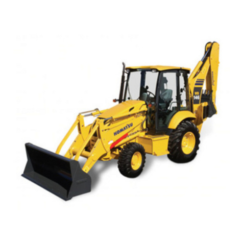
BACKHOE LOADER
SERIAL NUMBERS WB97R-2 97F20001 and up
This material is proprietary to Komatsu America Corp. and is not to be reproduced, used, or disclosed except in
accordance with written authorization from Komatsu America Corp.
It is our policy to improve our products whenever it is possible and practical to do so. We reserve the right to
make changes or improvements at any time without incurring any obligation to install such changes on products
sold previously.
Due to this continuous program of research and development, revisions may be made to this publication. It is
recommended that customers contact their distributor for information on the latest revision.
Copyright 2007 Komatsu
Printed in U.S.A.
Komatsu America Corp.
July 2007
00-2
WB97R-2
Find manuals at https://best-manuals.com
CONTENTS
WB97R-2
No. of page
10 STRUCTURE AND FUNCTION ............................................. 10-1
20 TESTING AND ADJUSTING ................................................ 20-1
30 DISASSEMBLY AND ASSEMBLY........................................... 30-1
40 MAINTENANCE STANDARD ............................................... 40-1
Find manuals at https://best-manuals.com
00-2
WB97R-2
Find manuals at https://best-manuals.com
Pages having no marks are those previousl revised
or made additions.
00-2-1
WB97R-2
Mark Indication Action required
CPage to be newl Add
cPage to be replaced Replace
( ) Page to be delete Discard
LIST OF REVISED PAGES
The affected pages are indicated b the use of the
following marks. It is requested that necessar ac-
tions be taken to these pages according to table
below.
Mark Page Time of
revision Mark Page Time of
revision
00-1
00-2
00-2-1
00-2-2
00-3
00-4
00-5
00-6
00-7
00-8
00-9
00-10
00-11
00-12
00-13
10-1
10-2
10-3
10-4
10-5
10-6
10-7
10-8
10-9
10-10
10-11
10-12
10-13
10-14
10-15
10-16
10-17
10-18
10-19
10-20
10-21
10-22
10-23
10-24
10-25
10-26
10-27
10-28
10-29
10-30
10-31
10-32
10-33
10-34
10-35
10-36
10-37
10-38
10-39
10-40
10-41
10-42
10-43
10-44
10-45
10-46
10-47
10-48
10-49
10-50
10-51
10-52
10-53
10-54
10-55
10-56
10-57
10-58
10-59
10-60
10-61
10-62
10-63
10-64
10-65
10-66
10-67
10-68
10-69
10-70
10-71
10-72
10-73
10-74
10-75
10-76
10-77
10-78
10-79
10-80
10-81
10-82
10-83
10-84
10-85
10-86
10-87
10-88
10-89
10-90
10-91
10-92
20-1
20-2
20-3
20-4
20-5
20-6
20-7
20-8
20-9
20-10
20-11
20-12
20-13
20-14
20-15
20-16
20-17
20-18
20-19
20-20
20-21
20-22
20-23
20-24
20-25
20-26
20-27
20-28
20-29
20-30
20-31
20-32
20-33
20-34
20-35
20-36
20-37
20-38
20-39
20-40
20-41
20-42
20-43
20-44
20-45
20-46
20-47
20-48
20-49
20-50
20-51
20-52
20-53
20-54
20-55
20-56
30-1
30-2
30-3
30-4
30-5
30-6
30-7
30-8
30-9
30-10
30-11
30-12
30-13
30-14
30-15
30-16
30-17
30-18
30-19
30-20
30-21
30-22
30-23
30-24
30-25
30-26
30-27
30-28
30-29
30-30
30-31
30-32
30-33
30-34
30-35
30-36
30-37
30-38
30-39
Find manuals at https://best-manuals.com
00-2-2
WB97R-2
Mark Page Time of
revision Mark Page Time of
revision
30-40
30-41
30-42
30-43
30-44
30-45
30-46
30-47
30-48
30-49
30-50
30-51
30-52
30-53
30-54
30-55
30-56
30-57
30-58
30-59
30-60
30-61
30-62
30-63
30-64
30-65
30-66
30-67
30-68
30-69
30-70
30-71
30-72
30-73
30-74
30-75
30-76
30-77
30-78
30-79
30-80
30-81
30-82
30-83
30-84
30-85
30-86
30-87
30-88
30-89
30-90
30-91
30-92
30-93
30-94
30-95
30-96
30-97
30-98
30-99
30-100
30-101
30-102
30-103
30-104
30-105
30-106
30-107
30-108
30-109
30-110
30-111
30-112
30-113
30-114
30-115
30-116
30-117
30-118
30-119
30-120
30-121
30-122
30-123
30-124
30-125
30-126
30-127
30-128
30-129
30-130
30-131
30-132
30-133
30-134
30-135
30-136
30-137
30-138
30-139
30-140
30-141
30-142
30-143
30-144
30-145
30-146
30-147
30-148
30-149
30-150
30-151
30-152
30-153
30-154
30-155
30-156
30-157
30-158
30-159
30-160
30-161
30-162
30-163
30-164
30-165
30-166
30-167
30-168
30-169
30-170
30-171
30-172
30-173
30-174
30-175
30-176
30-177
30-178
30-179
30-180
30-181
30-182
30-183
30-184
30-185
30-186
30-187
30-188
30-189
30-190
30-191
30-192
30-193
30-194
30-195
30-196
30-197
30-198
30-199
30-200
30-201
30-202
30-203
30-204
30-205
30-206
30-207
30-208
30-209
30-210
30-211
30-212
30-213
30-214
30-215
30-216
30-217
30-218
30-219
30-220
30-221
30-222
30-223
30-224
40-1
40-2
40-3
40-4
40-5
40-6
40-7
40-8
40-9
40-10
40-11
40-12
40-13
40-14
40-15
40-16
40-17
40-18
40-19
40-20
40-21
40-22
40-23
40-24
40-25
40-26
40-27
40-28
40-29
40-30
40-31
40-32
40-33
40-34
40-35
40-36
40-37
40-38
40-39
40-40
40-41
40-42
Find manuals at https://best-manuals.com
GENERAL PRECAUTIONS
Mistakes in operation extremel dangerous.
Read all the Operation and Maintenance Manual care-
full BEFORE operating the machine.
1. Before carr ing out an greasing or repairs, read
all the precautions written on the decals which
are suck on the machine.
2. When carr ing out an operation, alwa s wear
safet shoes and helmet. Do not wear loose work
clothes, or clothes with buttons missing.
.Alwa s wear safet glasses when hitting parts
with a hammer.
.Alwa s wear safet glasses when grinding
parts with a grinder, etc.
3. If welding repairs are needed, alwa s have a
trained, experienced welder carr out the work.
When carr ing out welding work, alwa s wear
welding gloves, apron, glasses, cap and other
clothes suited for welding work.
4. When carr ing out an operation with two or more
workers, alwa s agree on the operating procedure
before starting. Alwa s inform our fellow workers
before starting an step of the operation. Before
starting work, hang UNDER REPAIR signs on
the controls in the operator's compartment.
5. Keep all tools in good condition and learn the cor-
rect wa to use them.
6. Decide a place in the repair workshop to keep
tools and removed parts. Alwa s keep the tools
and parts in their correct places. Alwa s keep
the work area clean and make sure that there is
no dirt or oil on the floor.
Smoke onl in the areas provided for smoking.
Never smoke while working.
PREPARATIONS FOR WORK
7. Before adding or making an repairs, park the ma-
chine on hard, level ground, and block the wheels
to prevent the machine from moving.
8. Before starting work, lower outrigger, bucket or
an other work equipment to the ground. If this
is not possible, use blocks to prevent the work
equipment from falling down. In addition, be sure
to lock all the control levers and hang warning
sign on them.
9. When disassembling or assembling, support the
machine with blocks, jacks or stands before start-
ing work.
10. Remove all mud and oil from the steps or other
places used to get on and off the machine. Alwa s
use the handrails, ladders or steps when getting
on or off the machine.
Never jump on or off the machine.
If it is impossible to use the handrails, ladders or
steps, use a stand to provide safe footing.
PRECAUTIONS DURING WORK
11. When removing the oil filler cap, drain plug or h -
draulic pressure measuring plugs, loosen them
slowl to prevent the oil from spurting out.
Before disconnecting or removing components of
the h draulic circuit and engine cooling circuit,
first remove the pressure completel from the cir-
cuit.
12. The water and oil in the circuits are not hot when
the engine in stopped, so be careful not to get
burned.
Wait for the oil water to cool before carr ing out
an work on the cooling water circuits.
00-3
WB97R-2
IMPORTANT SAFETY NOTICE
Proper service and repair is extremel important for the safe operation of our machine.
The service and repair techniques recommended b FKI and describe in this manual are both effective
and safe methods of operation. Some of these operations require the use of tools speciall designed b
FKI for the purpose.
To prevent injur to workers, the s mbols and are used to mark safet precautions in this man-
ual. The cautions accompan ing these s mbols should alwa s be carefull followed. If an danger arises
or ma possibl arise, first consider safet , and take necessar steps to face.
SAFETY
Find manuals at https://best-manuals.com
13. Before starting work, remove the leads from the
batter . Alwa s remove the lead from the negative
( ± ) terminal first.
14. When raising heav components, use a hoist or
crane. Check that the wire rope, chains and hooks
are free from damage.
Alwa s use lifting equipment which has ample ca-
pacit . Install the lifting equipment at the correct
places.
Use a hoist or crane and operate slowl to prevent
the component from hitting an other part.
Do not work with an part still raised b the hoist
or crane.
15. When removing covers which are under internal
pressure or under pressure from a spring, alwa s
leave two bolts in position on opposite sides.
Slowl release the pressure, then slowl loosen
the bolts to remove.
16. When removing components, be careful not to
break or damage the wiring.
Damage wiring ma cause electrical fires.
17. When removing piping, stop the fuel or oil from
spilling out. If an fuel or oil drips on to the floor,
wipe it up immediatel .
Fuel or oil on the floor can cause ou to slip, or
can even start fires.
18. As a general rule, do not use gasoline to wash
parts. In particular, use onl the minimum of gaso-
line when washing electrical parts.
19. Be sure to assemble all parts again in their origi-
nal places. Replace an damage parts with new
parts.
.When installing hoses and wires, be sure that
the will not be damaged b contact with other
parts when the machine is being operated.
20. When installing high pressure hoses, make sure
that the are not twisted. Damaged tubes are dan-
gerous, so be extremel careful when installing
tubes for high pressure circuits. Also, check that
connecting parts are correctl tightened.
21. When assembling or installing parts, alwa s use
specified tightening torques.
When installing the parts which vibrate violentl or
rotate at high speed, be particular careful to
check that the are correctl installed.
22. When aligning two holes, never insert our fingers
or hand.
23. When measuring h draulic pressure, check that
the measuring tool is correctl assembled before
taking an measurement.
24. Take sure when removing or installing tracks of in
particular rubber tracks. When removing the
track, the track separates suddenl , so never let
an one stand at either end of the wheel.
00-4
WB97R-2
Find manuals at https://best-manuals.com
00-5
WB97R-2
FOREWORD
This shop manual has been prepared as an aid to improve the qualit of repairs b giving the operator an ac-
curate understanding of the product and b showing him the correct wa to perform repairs and make judgements.
Make sure ou understand the contents of this manual and use it to full effect at ever opportunit .
This shop manual mainl contains the necessar technical information for operations performed in a service
workshop.
The manual is divided into chapters on each main group of components; these chapters are further divided into
the following sections.
STRUCTURE AND FUNCTION
This section explains the structure and function of each component. It serves not onl to give an under-
standing of the structure, but also serves as reference material for troubleshooting.
TESTING AND ADJUSTING
This sections explains checks to be made before and after performing repairs, as well as adjustments to be
made at completion of the checks and repairs.
Troubleshooting charts correlating «Problems» to «Causes» are also included in this section.
DISASSEMBLY AND ASSEMBLY
This section explains the order to be followed when removing, installing, disassembling or assembling
each component, as well as precautions to be taken for these operations.
MAINTENANCE STANDARD
This section gives the judgement standards when inspecting disassembled parts.
NOTICE
The spe ifi ations ontained in this shop manual are subje t to hange at any time and without any
noti e.
Conta t your FKI distributor for the latest information.
Find manuals at https://best-manuals.com
VOLUMES
Shop manual are issued as a guide to carr out re-
pairs. These various volumes are designed to avoid
duplicating the same information.
DISTRIBUTION AND UPDATING
An additions, amendments or other changes will
be sent to FKI distributors.
Get the most up-to-date information before ou start
an work.
FILING METHOD
1. See the page number on the bottom of the page.
File the pages in correct order.
2. Following examples show ou how to read the
page number.
Example
3. Additional pages: additional pages are indicated
b a h phen (-) and number after the page num-
ber.
Fle as in the example.
Example:
10-4
10-4-1
10-4-2
10-5
]Added pages
REVISED EDITION MARK
(123....)
When a manual is revised, an edition mark is re-
corded on the bottom outside corner of the pages.
REVISIONS
Revised pages are shown on the LIST OF RE-
VISED PAGES between the title page and SAFETY
page.
SYMBOLS
In order to make the shop manual greatl chelpful,
important points about safet and qualit are marked
with the following s mbols.
S mbol Item Remarks
Safet
Special safet precautions are ne-
cessar when performing the
work.
Extra special safet precautions
are necessar when performing
the work because it is under inter-
nal pressure.
Caution
Special technical precautions or
other precautions for preserving
standards are necessar when
performing the work.
Weight
Weight of parts or s stems.
Caution necessar when selecting
hoisting wire, or when working
posture is important, etc.
Tightening
torque
Parts that require special attention
for the tightening torque during as-
sembl .
Coat Parts to be coated with adhesives
and lubricants etc.
Oil, water Places where oil, water or fuel
must be added, and their quantit .
Drain
Places where oil or water must be
drained, and quantit to be
drained.
HOW TO READ THE SHOP MANUAL
00-6
WB97R-2
Item number (10. Structure and
Function)
Consecutive page number for eac
h
item.
10 - 3
Find manuals at https://best-manuals.com
Heav parts (25 kg or more) must be lifted
with a hoist etc. In the Disassembly and As-
sembly section, ever part weighing 25 kg or
more is clearl indicated with the s mbol
1. If a part cannot be smoothl removed from the

machine b hoisting, the following checks should
be made:
.Check for removal of all bolts fastening the part
to the relative parts.
.Check for an part causing interference with
the part to be removed.
2. Wire ropes
1) Use adequate ropes depending on the weight
of parts to be hoisted, referring to the table be-
low:
WIRE ROPES
(Standard «S» or «Z» twist ropes
without galvanizing)
Rope diameter (mm) Allowable load (tons)
10
11.2
12.5
14
16
18
20
22.4
30
40
50
60
1.0
1.4
1.6
2.2
2.8
3.6
4.4
5.6
10.0
18.0
28.0
40.0
The allowable load value is estimated to be
one-sixth or one-seventh of the breaking
strength of the rope used.
2) Sling wire ropes from the middle portion of the
hook. Slinging near the edge of the hook ma
cause the rope to slip off the hook during hoist-
ing, and a serious accident can result.
Hooks have maximum strength at the middle
portion.
3) Do not sling a heav load with one rope alone,
but sling with two or more ropes s mmetricall
wound on to the load.
Slinging with one rope ma cause turning of
the load during hoisting, untwisting of the
rope, or slipping of the rope from its original
winding position on the load, which can
cause dangerous accidents.
4) Do not sling a heav load with ropes forming a
wide hanging angle from the hook.
When hoisting a load with two or more ropes,
the force subjected to each rope will increase
with the hanging angles.
The table below shows the variation of allow-
able load (kg) when hoisting is made with two
ropes, each of which is allowed to sling up to
1000 kg verticall , at various handing angles.
When two ropes sling a load verticall , up to
2000 kg of total weight can be suspended.
This weight becomes 1000 kg when two ropes
make a 120ë hanging angle.
On the other hand, two ropes are subjected to
an excessive force as large as 4000 kg if the
sling a 2000 kg load at a lifting angle of 150ë.
HOISTING INSTRUCTIONS
00-7
WB97R-2
STANDARD TIGHTENING TORQUE
00-8
WB97R-2
The following charts give the standard tightening torques of bolts and nuts. Exceptions are given in sections of «Dis-
assembly and Assembly».
1. STANDARD TIGHTENING TORQUE OF BOLTS AND NUT
Thread diameter
of bolts
(mm)
Pitch of
bolts
(mm)
Width across flat
(mm)
kgm Nm kgm Nm
6
8
10
12
14
1
1.25
1.5
1.75
2
10
13
17
19
22
5
6
8
10
12
0.96w0.1
2.3w0.2
4.6w0.5
7.8w0.8
12.5w1
9.5w1
23w2
45w4.9
77w8
122w13
1.3w0.15
3.2w0.3
6.5w0.6
11w1
17.5w2
13.5w1.5
32.2w3.5
63w6.5
108w11
172w18
16
18
20
22
24
2
2.5
2.5
2.5
3
24
27
30
32
36
14
14
17
17
19
19.5w2
27w3
38w4
52w6
66w7
191w21
262w28
372w40
511w57
644w70
27w3
37w4
53w6
73w8
92w10
268w29
366w36
524w57
719w80
905w98
27
30
33
36
39
3
3.5
3.5
4
4
41
46
50
55
60
19
22
24
27
Ð
96w10
131w14
177w20
230w25
295w33
945w100
1287w140
1740w200
2250w250
2900w330
135w15
184w20
250w27
320w35
410w45
1329w140
1810w190
2455w270
3150w350
4050w450
This torque table does not appl to bolts or nuts which have to fasten n lon or other parts non-ferrous metal washer.
.Nm (Newton meter): 1 Nm = 0.102 kgm
STANDARD TIGHTENING TORQUE
00-9
WB97R-2
2. TIGHTENING TORQUE FOR NUTS OF FLARED
Use these torques for nut part of flared.
Thread diameter
of nut part
(mm)
Width across flats
of nut part
(mm)
TIGHTENING TORQUE
kgm Nm
1/2" - 20
9/16" - 18
3/4" - 16
7/8" - 14
1.
1
/16
"
-12
1.
5
/16
"
-12
1.
5
/8
"
-12
22
33
17
17
22
27
32
38
50
27
41
2.6w0.5
4w0.5
6.7w2
8w2
9.7w3
17w3
20w5
8w2
20w5
25.5w4.9
39.2w4.9
65.7w19.6
78.5w19.6
95.15w29.4
166.7w29.4
196.2w49
78.5w19.6
196.2w49
Thread diameter
of nut part
(mm)
Width across flats
of nut part
(mm)
TIGHTENING TORQUE
kgm Nm
9/16" - 18
11/16" - 16
13/16" - 16
1" - 14
1.
3
/16
"
-12
1.
7
/16
"
-12
1.
11
/16
"
-12
2" - 12
17
22
24
30
36
41
50
57
2.3 ± 2.5
3.4 ± 3.9
5.2 ± 5.8
8.2 ± 9.2
12.2 ± 13.3
15.3 ± 17.3
18.4 ± 20.4
20.4 ± 24.4
23 ± 25
33 ± 38
51 ± 57
80 ± 90
120 ± 130
150 ± 170
180 ± 200
200 ± 240
Superficie di tenuta
Sealing surface
00-10
WB97R-2
COATING MATERIALS
The recommended coating materials prescribed in FKI Shop Manuals are listed below:
Nomenclature Code Applications
Adhesives
ASL800010 Used to appl rubber pads, rubber gaskets and cork plugs.
ASL800020 Used to appl resin, rubber, metallic and non-metallic parts when a fast, strong
seal is needed.
Loctite 222 Used for low resistance locking of screws, check nuts and adjustment nuts.
Loctite 242
To prevent the loosening of bolts, nuts and plugs and the leakage of oil. Used for
medium resistance locking of screws and nuts of ever t pe, and for locking ke s
and bearings.
Loctite 262 Used for high resistant of threaded parts that can be removed with normal tools.
Loctite 270 Used for high resistant locking and for sealing threaded parts, bolts and stud bolts.
Loctite 542 Used for sealing the union threads for h draulic tubes.
Loctite 573 Used for sealing rather exact plane surfaces when the option of possible future
dismantling is required.
Loctite 601 Used for high resistant locking of mechanical components that can be removed
onl after heating
Loctite 675
Used to lock c lindrical couplings and for the permanent locking of threaded parts,
and also to lock shafts to bearings, gears, pulle s, pins, bushings, etc.
Gasket sealant
ASL800060 Used b itself to seal grease fittings, tapered screw fittings and tapered screw fit-
tings in h draulic circuits of less than 50 mm in diameter.
Loctite 510 Used b itself on mounting flat surface
(Clearance between surfaces within 0.2 mm)
Loctite 518 Used b itself on mounting flat surface
(Clearance between surfaces within 0.5 mm)
Antifriction compound
(Lubricant including
Mol bdenum disulfide)
ASL800040 Applied to bearings and taper shaft to facilitate press-fitting and to prevent stick-
ing, burning or rusting.
Grease
(Lithium grease) ASL800050 Applied to bearings, sliding parts and oil seals for lubrication, rust prevention and
facilitation of assembling work.
Vaseline ±Used for protecting batter electrode terminals from corrosion.
ELECTRIC WIRE CODE
ELECTRIC WIRE CODE
00-11
WB97R-2
n the wiring diagrams various colours and s mbols are emplo ed to indicate the thickness of wires.
This wire code table will help ou understand WIRING DIAGRAMS.
Example: R -N 1.5 indicates a cable having a nominal number 1.5 and red coating with black stripe.
CLASSIFICATION BY THICKNESS
Nominal
number
Copper wire Cable O.D.
(mm)
Current rating
(A)
Number
strands
ù of strands
(mm)
Cross section
(mm
2
)
1 14 0.30 0.99 2.80 11
1.5 21 0.30 1.48 3.32 14
2.5 35 0.30 2.47 3.80 20
4 56 0.30 3.95 4.60 28
6 84 0.30 5.93 5.20 37
10 84 0.40 10.55 7.10 53
50 399 0.40 50.11 14.00 160
CLASSIFICATION BY COLOUR AND CODE
Primar Auxiliar
Code A A-B ± A-G ± A-N A/N A-R A/R A-V A/V
Colour Light blue Light blue - White Light blue - Yellow Light blue - Black Light blue - Red Light blue - Green
Code B B-G ± B-N B/N B-R B/R ± B/V ±±
Colour White White - Yellow White - Black White - Red White - Green ±
Code C C-B C/B C-L ± C-N ±±±±±
Colour Orange Orange - White Orange - Blue Orange - Black ± ±
Code G ± G/N ± G-R ± G-V ±±±±
Colour Yellow Yellow - Black Yellow - Red Yellow - Green ± ±
Code H H-L ± H/N ±±±±±±±
Colour Gra Gra - Blue Gra - Black ± ± ±
Code L L-B L/B ± L/N L-G ±±±±±
Colour Blue Blue - White Blue - Black Blue - Yellow ± ±
Code M M-B ± M-N M/N M-V ±±±±±
Colour Brown Brown - White Brown - Black Brown - Green ± ±
Code N ±±±±±±±±±±
Colour Black ±±±±±
Code R R-G ± R-N R/N R-V ±±±±±
Colour Red Red - Yellow Red - Black Red - Green ± ±
Code S S-N ± S-G ±±±±±±±
Colour Pink Pink - Black Pink - Yellow ± ± ±
Code V V-B ± V-N V/N ±±±±±±
Colour Green Green - White Green - Black ± ± ±
Code Z Z-B Z/B Z-N Z/N ±±±±±±
Colour Violet Violet - White Violet - Black ± ± ±
COMPOSITION OF THE COLOURS
The coloration of two-colour wires is indicated b the composition of the s mbols listed.
Example: G-V = Yellow-Green with longitudinal colouring.
G/V = Yellow-Green with transversal colouring.
ELECTRIC
WEIGHT TABLE
00-12
WB97R-2
This weight table is a guide for use when transporting or handling components.
Unit: kg
Machine model WB97R-2
From serial no. 97F20001±
Engine assembl - Muffler - Exhaust pipe 410
Radiator - exchanger 37
H draulic tank (without h draulic oil) Ð
Fuel tank (without fuel) Ð
Front counterweight 300
Engine hood Ð
Cab (without seat) 595
Seat 34
Engine - gear-box - pump group 740
Piston pump 38
Transmission 230
Convertor Ð
Front axle 316
Rear axle 511
Front wheel
Rear wheel
65
163
2-spool control valve 24
3-spool control valve 30
Work equipment Ð
Backhoe
Work equipment Ð
Boom 323
Arm 213
Long arm 245
Boom swing bracket 133
Backframe Ð
6-spool control valve 47
7-spool control valve 53
8-spool control valve 59
Jig arm 392
Outriggers Ð
Boom c linder 78
Arm c linder 69
Bucket c linder 49
Outrigger c linder Ð
Swing c linder 30
TABLE OF OIL AND COOLANT QUANTITIES
00-13
WB97R-2
RESERVOIR KIND OF
FLUID
AMBIENT TEMPERATURE CAPACITY ( <)
±20 ±10 0 10 20 30ëC Spe ified Refill
Crankcase sump OIL
.API CD 8.6 8.6
H draulic circuit OIL
.API CD 150 92
Front axle
.differential
OIL
.UTTO FLUID
6.5 6.5
.final red. gear
(each) 11
Rear axle:
.differential 15 15
.final red. gear
(each) 3.5 3.5
H draulic
transmission
OIL
.
GM DEXRON
t
II D
(DEXRON
t
is a regis-
tered trademark of Gen-
eral Motors Corporation)
19 16
Braking s stem 0.8 0.8
Fuel tank DIESEL OIL 130 Ð
Engine coolant
s stem
WATER+
ANTI-FREEZE 18 Ð
WATER 18 Ð
PERMANENT
LIQUID 18 Ð
]ASTM D975 N. 1
FKI 907 OLDEN TURBO UNIGRADO
FKI 909 MULTISERVICE 4
FKI 918 SPECIAL TRANSMISSION FLUID 68/F-100
FKI 921 ANDROS FLUID II D
FKI 921 ANTIFROST PRONTO (±25 ëC)
FKI 907 10W
FKI 907 20W-20
FKI 907 SAE 30
FKI 907 SAE 40
FKI 909 10W-30
FKI 918
FKI 921
FKI 921
]
ASTM D975 N. 2
FKI 931
00-14
WB97R-2
ASTM: America Societ of Testing and Materials
SAE: Societ of Automotive Engineers
API: American Petroleum Institute
MIL: USA Militar Specification
CCMC: Common Market Constructors Committe
First filling quantity: total quantit of oil, including the oil for the components and pipes.
Oil hange quantity: quantit of oil necessar to fill the s stem or unit during the normal inspection and mainte-
nance operations.
NOTE:
(1) When the diesel oil sulphur content is less then 0.5%, change the engine oil according to the periodic mainte-
nance intervals indicated in the operation and maintenance manual. In the diesel oil sulphur content exceeds
0.5% change the engine oil according to the following table:
Sulphur ontent Engine oil hange interval
from 0.5 to 1.0% 1/2 of regular interval
over 1.0% 1/4 of regular interval
(2) When starting the engine at temperatures below 0 ëC, use engine oil SAE 10W, 20W-20 and 10W-30, even if
during the da the temperature increases b 10 ëC.
(3) Use engine oil with CD classification; if oil with CD classification is used, reduce the engine oil change interval
b a half.
(4) Use original products, which have characteristics specificall formulated and approved for the engine, the h -
draulic circuit of equipment and for reductions.
10-1
WB97R-2
STRUCTURE AND FUNCTION
Power train ............................................. 2
Transmission ........................................... 4
Drive shafts ............................................. 8
Control valve blo k.................................... 10
Front axle .............................................. 12
Rear axle .............................................. 15
Hydrauli pump ....................................... 20
Hydrauli steering system............................ 41
Hydrauli ir uit ....................................... 43
Shovel ontrol valve .................................. 44
Ba khoe ontrol valve ................................ 50
CLSS ................................................... 57
Solenoid valve......................................... 71
Safety valve............................................72
Brake pump. ...........................................74
Shovel ylinders .......................................75
Ba khoe ylinders.....................................76
Air- onditioning unit ...................................80
How the air- onditioning unit fun tions..............81
Ele tri al diagram (1/7) ...............................83
Ele tri al diagram (2/7) ...............................85
Ele tri al diagram (3/7) ...............................87
Ele tri al diagram (4/7) ...............................89
Ele tri al diagram (5/7) ...............................91
Ele tri al diagram (6/7) ...............................93
Ele tri al diagram (7/7) ...............................95
DESCRIPTION
.The driving power for the engine (1) is transmitted
through the flywheel to the onverter (2).
The onverter (2) uses hydrauli oil to onvert the
torque transmitted by the engine (1) into driving po-
wer. The onverter (2) transmits motion to the drive
shaft of the transmission (3) and to the drive shaft
of the hydrauli pump (4).
.The transmission (3) has two hydrauli ally-a tiva-
ted lut hes that an be sele ted by an ele tri al-
ly- ontrolled gear sele tor. It also has manual gear
sele tion (four forward gears and four reverse
gears).
.The driving power is transmitted from the transmis-
sion flanges (3) to the front (5) and rear (6) axles
through the Cardan drive shafts (7 and 8).
.The driving power transmitted to the front (5) and
rear (6) axles is redu ed by the differentials and
then transmitted to the planetary gear through the
differential shafts.
POWER TRAIN
10-2
WB97R-2
RKZ01060
1234
56
8
7

Other manuals for avance WB97R-2

1

This manual suits for next models

1

Other Komatsu Compact Loader manuals

Komatsu WB140-2N Manual

Komatsu

Komatsu WB140-2N Manual

Komatsu A76001 Install guide

Komatsu

Komatsu A76001 Install guide

Komatsu WA600-6 Manual

Komatsu

Komatsu WA600-6 Manual

Komatsu WB146-5 Install guide

Komatsu

Komatsu WB146-5 Install guide

Komatsu WA480-8 Manual

Komatsu

Komatsu WA480-8 Manual

Komatsu WA480-6 Manual

Komatsu

Komatsu WA480-6 Manual

Komatsu WA380-6H User manual

Komatsu

Komatsu WA380-6H User manual

Komatsu A96001 Install guide

Komatsu

Komatsu A96001 Install guide

Komatsu D155AXi -8 Install guide

Komatsu

Komatsu D155AXi -8 Install guide

Komatsu WB140-2N Manual

Komatsu

Komatsu WB140-2N Manual

Komatsu WA200-7 Install guide

Komatsu

Komatsu WA200-7 Install guide

Komatsu WA250-6 Manual

Komatsu

Komatsu WA250-6 Manual

Komatsu WA320-5H Manual

Komatsu

Komatsu WA320-5H Manual

Komatsu WB146PS-5 Install guide

Komatsu

Komatsu WB146PS-5 Install guide

Komatsu D475A-5 Install guide

Komatsu

Komatsu D475A-5 Install guide

Komatsu GALEO WA450-5L Install guide

Komatsu

Komatsu GALEO WA450-5L Install guide

Komatsu WA500-3H Install guide

Komatsu

Komatsu WA500-3H Install guide

Komatsu avance WB97R-2 Manual

Komatsu

Komatsu avance WB97R-2 Manual

Komatsu WA600-8 Manual

Komatsu

Komatsu WA600-8 Manual

Komatsu SK1020-5NA Manual

Komatsu

Komatsu SK1020-5NA Manual

Komatsu WB93R-5 Manual

Komatsu

Komatsu WB93R-5 Manual

Komatsu avance plus WA180PT-3MC Install guide

Komatsu

Komatsu avance plus WA180PT-3MC Install guide

Komatsu H75051 Manual

Komatsu

Komatsu H75051 Manual

Komatsu WA65-3 Manual

Komatsu

Komatsu WA65-3 Manual

Popular Compact Loader manuals by other brands

Kubota SVL75-3 Operator's manual

Kubota

Kubota SVL75-3 Operator's manual

Changlin Company 957H manual

Changlin Company

Changlin Company 957H manual

Erskine Attachments Cold Planer 18 Operator's manual

Erskine Attachments

Erskine Attachments Cold Planer 18 Operator's manual

Toro DINGO 525 Safety instruction

Toro

Toro DINGO 525 Safety instruction

Toro 22323G Operator's manual

Toro

Toro 22323G Operator's manual

Toro Dingo 22429 Operator's manual

Toro

Toro Dingo 22429 Operator's manual

MultiOne 2 Series instruction manual

MultiOne

MultiOne 2 Series instruction manual

RHINO LOADER 4211 Operator's manual

RHINO

RHINO LOADER 4211 Operator's manual

RAMROD 930 Operator's manual

RAMROD

RAMROD 930 Operator's manual

Ditch Witch SK800 Operator's manual

Ditch Witch

Ditch Witch SK800 Operator's manual

Avantco Jib boom 300 Series Operator's manual

Avantco

Avantco Jib boom 300 Series Operator's manual

Wacker Neuson Telehandler TH412 Operator's manual

Wacker Neuson

Wacker Neuson Telehandler TH412 Operator's manual

Baumalight TRL620Y Operator's manual

Baumalight

Baumalight TRL620Y Operator's manual

Case 1021G Service manual

Case

Case 1021G Service manual

jcb 411HT Operator's manual

jcb

jcb 411HT Operator's manual

Toro 22520 Operator's manual

Toro

Toro 22520 Operator's manual

ASV RT-40 Operation and maintenance manual

ASV

ASV RT-40 Operation and maintenance manual

Giant-Vac 65hp Series manual

Giant-Vac

Giant-Vac 65hp Series manual

manuals.online logo
manuals.online logoBrands
  • About & Mission
  • Contact us
  • Privacy Policy
  • Terms and Conditions

Copyright 2025 Manuals.Online. All Rights Reserved.