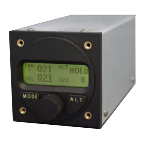
Kongsberg Simrad AP20 User manual

Simrad AP20
Autopilot
ALWAYS AT THE FOREFRONT OF TECHNOLOGY
MANUAL

This page is intentionally left blank

Instruction manual
20220505H 1
Instruction Manual
This manual is intended as a reference guide for operating and
correctly installing the AP20 autopilot.
Great care has been paid to simplify operation and set-up of the
Simrad AP20, however, an autopilot is a complex electronic
system. It is affected by sea conditions, speed of the vessel, hull
shape and size.
Please take time to read this manual to get a thorough
understanding of the operation and system components and their
relationship to a complete AP20 autopilot system.
Other documentation material that is included in this manual is a
warranty card. This must be filled out by the authorized dealer that
performed the installation and mailed in to activate the warranty.

Simrad AP20 Autopilot
220220505H
Document revisions
Written by Checked by Approved by
Rev Date Sign Date Sign Date Sign
– 22.03.97 N.G. 22.03.97 G.K. 22.03.97 Th.H.
A 07.10.97 N.G. 07.10.97
Th.H.
B 22.06.98 N.G. 22.06.98
Th.H.
C 20.12.99 N.G. 20.12.99
Th.H.
D 27.03.00 N.G. 27.03.00
Th.H.
E 20.06.00 N.G. 20.06.00
Th.H.
F 28.08.01 N.G. 28.08.01
I.K.
G 15.05.02 N.G. 15.05.02 I.K. 15.05.02 Th.H.
H 12.02.04 12.02.04
Document history
Rev. – First edition
Rev. A Modified system drawings, Figure 1-1 and 4-1. Drawings for junction unit
terminal boards included. Page 18: Amendment to operational sequence of
R3000X. Description of AP300PX connection included. Modified
Installation menu, figure 4-28. NMEA sentence specifications included.
Quick reference guide included.
Rev. B Course adjustment selectable between 1° and 10° per push with software
version V1R2 (page 19, 27, 32, 33 and 114). New structure for mounting
accessories, page 118. Minor correction of display screens on page 24, 25
and 88. FU35 Follow-up Steering Lever included on page 12. New
distributor list.
Rev. C AP21 included on drawing page 55. Removed AP300P.
AP21 Connection on page 67 included. LFI3000 substituted by LFI3000
Mk2.
Rev. D Modified note on page 117.
Rev. E New art. no. on Robnet connectors, page 120. New gasket added on page 64
and under Standard mounting kit, page 118. Minor modifications in text.
Rev. F IS11 instruments replaced by IS15. Added RPU300, 24V to the table on
page 58. CD100A included. Minor corrections to text and display pictures.
Rev. G Updated according to software versions AP20 V1R3 and J300X V1R8.
Rev. H Added note on page 70. Fig. 4-17 and 4-18 modified.

Instruction manual
20220505H 3
Contents
1 INTRODUCTION ....................................................................................... 8
1.1 General .................................................................................................. 8
1.2 How to use this manual......................................................................... 8
1.3 System components............................................................................... 9
1.4 AP20 Control Unit ..............................................................................10
1.5 Junction units ......................................................................................10
1.6 RF300 Rudder Feedback unit .............................................................10
1.7 Heading Sensors..................................................................................10
RFC35 Electronic Fluxgate Compass.................................................11
RFC35R Rate compass .......................................................................11
CDI35 Course Detector Interface and CD100A Course Detector......11
NMEA compass .................................................................................. 11
Other fluxgate compass models .......................................................... 11
Simrad RGC10 and RGC50 gyrocompasses ......................................11
1.8 Optional equipment.............................................................................12
R3000X Remote Control ....................................................................12
S35 NFU Lever ...................................................................................12
FU35 Follow-Up Steering Lever ........................................................12
NI300X NMEA Interface Unit ........................................................... 12
CI300X Compass Interface.................................................................12
2 Operation of the autopilot......................................................................... 13
2.1 Overview.............................................................................................13
2.2 ON/OFF - Standby mode .................................................................... 14
Flashing course knob icon ..................................................................15
2.3 AP20 with MSD50 Stern Drive unit................................................... 15
Zero point setting ................................................................................ 15
Operation.............................................................................................16
2.4 Follow-Up steering (FU)..................................................................... 16

Simrad AP20 Autopilot
420220505H
2.5 Non-Follow-Up steering (NFU) ......................................................... 17
2.6 R3000X Remote Control .................................................................... 18
2.7 S35 Steering lever ...............................................................................18
2.8 Automatic Steering .............................................................................18
2.9 Automatic Speed selection.................................................................. 19
2.10 Manual speed selection ....................................................................... 20
2.11 Navigating with the AP20................................................................... 21
2.12 Selecting a different Navigator ...........................................................23
2.13 Dodging............................................................................................... 24
2.14 Dodge in NAV .................................................................................... 25
2.15 TURN-mode........................................................................................ 25
2.16 Tacking in Auto mode ........................................................................ 26
2.17 Wind vane steering.............................................................................. 27
2.18 Tacking in Wind mode........................................................................ 28
2.19 Multiple station system ....................................................................... 28
2.20 Lock function ...................................................................................... 29
2.21 User Set-up Menu ............................................................................... 31
2.22 Instrument screens and menu.............................................................. 34
Instrument set-up................................................................................. 36
Flashing course knob icon ..................................................................36
3 Technical Specifications ............................................................................ 37
3.1 AP20 Autopilot System ......................................................................37
3.2 AP20 Control Unit ..............................................................................38
3.3 Junction units ......................................................................................40
3.4 RFC35 Fluxgate compass ................................................................... 42
3.5 RFC35R Rate compass ....................................................................... 43
3.6 CDI35 Course Detector Interface .......................................................43
3.7 RF300 Rudder Feedback..................................................................... 44
3.8 CI300X Compass Interface.................................................................45
3.9 NI300X NMEA Interface ................................................................... 46
3.10 R3000X Remote Control .................................................................... 47

Instruction manual
20220505H 5
3.11 S35 NFU Steering Lever..................................................................... 47
3.12 NMEA messages................................................................................. 48
3.13 IP protection ........................................................................................ 50
4 Installation.................................................................................................. 51
4.1 General ................................................................................................51
4.2 Installation checklist ...........................................................................51
4.3 Unpacking and handling .....................................................................52
4.4 Determine system configuration .........................................................52
4.5 AP20 System Layout ..........................................................................53
4.6 RF300 Rudder feedback installation................................................... 53
4.7 Junction unit installation .....................................................................55
4.8 Cable connections ...............................................................................56
4.9 Grounding and RFI .............................................................................56
4.10 Drive unit installation.......................................................................... 58
Connecting a reversible pump ............................................................60
Connecting a hydraulic linear drive.................................................... 61
Connecting a solenoid valve ...............................................................61
4.11 Control unit installation ......................................................................62
Panel mounting ................................................................................... 62
Alternative panel mounting.................................................................62
Optional bracket mounting .................................................................63
4.12 ROBNET network cables ................................................................... 63
AP21 connection.................................................................................65
4.13 RFC35 Fluxgate Compass installation ...............................................66
4.14 RFC35R Rate Compass installation.................................................... 67
4.15 R3000X Remote Control installation .................................................69
4.16 S35 NFU Lever installation ................................................................69
4.17 Interfacing ...........................................................................................70
4.18 Single NMEA input/output.................................................................70
4.19 Double NMEA input/output ............................................................... 71
4.20 Additional NMEA output on Port 2.................................................... 71

Simrad AP20 Autopilot
620220505H
4.21 NMEA Compass in ............................................................................. 71
4.22 Radar Clock/Data................................................................................ 72
4.23 IS15 Instrument installation................................................................72
4.24 External Alarm .................................................................................... 74
4.25 NI300X NMEA Interface Unit ........................................................... 74
4.26 CI300X Analogue Interface Unit........................................................ 76
4.27 LF3000 Linear Feedback ....................................................................77
4.28 CD100A Course Detector ................................................................... 79
4.29 CDI35 Interface................................................................................... 80
4.30 Software Setup Procedure...................................................................81
Description of Installation Settings..................................................... 81
Installation Menu ................................................................................ 82
Language selection.............................................................................. 84
4.31 Dockside settings ................................................................................85
Drive unit voltage selection ................................................................ 85
Rudder Feedback Calibration .............................................................86
Automatic Rudder Test .......................................................................88
Transition Speed ................................................................................. 89
Interface Settings................................................................................. 90
4.32 Sea Trial .............................................................................................. 96
Rudder zero adjust .............................................................................. 96
Compass calibration............................................................................ 97
Compass Offset ................................................................................... 98
Automatic tuning................................................................................. 99
View parameters ...............................................................................101
Manual parameter adjust................................................................... 101
NMEA Test .......................................................................................103
Display Units..................................................................................... 103
Master Reset...................................................................................... 104
Final sea trial.....................................................................................104
Providing user training......................................................................105

Instruction manual
20220505H 7
5 Maintenance .............................................................................................106
5.1 Control unit .......................................................................................106
5.2 Junction Unit ..................................................................................... 106
5.3 Rudder Feedback...............................................................................106
5.4 Compass ............................................................................................106
5.5 Drive unit .......................................................................................... 106
5.6 Exchange of software programme .................................................... 107
6 Trouble shooting ...................................................................................... 109
6.1 Alarms...............................................................................................109
6.2 System Data Menu ............................................................................ 113
6.3 NMEA Data Menu............................................................................114
Decoding ...........................................................................................114
NMEA signal monitor.......................................................................115
NMEA (hardware) test...................................................................... 116
7 Spare Parts List........................................................................................ 117
8 Glossary .................................................................................................... 120
SALES AND SERVICE WORLDWIDE
TERMS OF WARRANTY
WARRANTY CARD
QUICK REFERENCE GUIDE
English
German
French
Italian
Spanish
Dutch
Swedish
Norwegian

Simrad AP20 Autopilot
820220505H
1INTRODUCTION
1.1 General
Congratulations on the purchase of your new Simrad AP20
autopilot system and thank you for selecting what we feel is the
most advanced autopilot system available on the market today.
Today, Simrad manufactures a complete range of autopilots for
all types of vessels, from leisure boats to advanced steering
systems for merchant marine vessels. Our factory for these
products Simrad Egersund AS, is located in Egersund on the
southwest coast of Norway. The company's involvement in
autopilots began in 1953 with equipment for the North Sea
fishing fleet under the brand name Robertson. Professional
mariners around the world acknowledge that the Robertson and
Simrad brand names are synonymous with the absolute best in
autopilot technology.
The Simrad AP20 autopilot represents yet another step forward
in autopilot technology with the intent of providing leisure boats
between 30 and 80 foot with a host of new features. The system
can be expanded and enhanced with a selection of options and
accessories.
The brain in the AP20 autopilot system is the single "intelligent"
junction unit that communicates with all other system modules
on the ROBNET network. The ROBNET has been developed to
establish a reliable digital communication and power distribution
network between the units in the system. The ROBNET
simplifies installation and enables the AP20 system to be easily
expanded at any time.
1.2 How to use this manual
This manual is intended as a reference guide for operating,
installing and maintaining the Simrad AP20 autopilot. Great care
has been paid to simplify operation and set-up of the AP20,
however, an autopilot is a complex electronic system. It is
affected by sea conditions, speed of the vessel, hull shape and
size.

Introduction
20220505H 9
Please take time to read this manual to get a thorough
understanding of the operation and system components and their
relationship to a complete AP20 autopilot system.
Other documentation material that is provided with your system
includes a warranty card. This must be filled out by the
authorized dealer that performed the installation and mailed in to
activate the warranty.
1.3 System components
A basic AP20 system consists of the following units (refer to
Figure 1-1):
•AP20 Control Unit with accessories
•Heading sensor
•Rudder Feedback Unit with transmission link
•Junction Unit
•Drive unit
The basic system can be expanded with remote control unit,
hand held remote and steering lever.
Figure 1-1 AP20 Basic system

Simrad AP20 Autopilot
10 20220505H
1.4 AP20 Control Unit
A compact autopilot control for panel, bulkhead or bracket
mounting. Large LCD display for readout of autopilot data and
rotary course knob. It has two Robnet connectors for system
interconnection and expansion.
1.5 Junction units
The junction unit is the heart in the AP20 autopilot system. It
contains the steering computer, interface circuits to all system
components and drive circuits for the drive unit motor and
clutch. Three models, J300X, J300X-40 and J3000X are
available.
Junction unit comparison chart:
J3000X J300X (J300X-40)
Supply voltage 10-28 V 10-40 V
Motor current
(continuous/peak)
6/10 A 10/20A (20/40A)
Clutch/bypass current 1,5 A 1,5 A
Number of control units 2 5
NMEA ports (input/output) 1 2
Solenoid output x x
Input for NFU control x x
External alarm x
Radar clock/data interface x
1.6 RF300 Rudder Feedback unit
Rudder feedback unit with transmission link and 10 m (30 feet)
of cable. Transforms the angular travel of the rudder to a digital
signal read by the autopilot steering computer.
1.7 Heading Sensors
The AP20 autopilot can be used with the following combinations
of heading sensors:

Introduction
20220505H 11
RFC35 Electronic Fluxgate Compass
A compact heading sensor from Simrad with 15 m (45 feet) of
cable. The direction of the earth's magnetic field is sensed by a
floating ring core in a fluxgate coil and transformed to a digital
signal read by the autopilot steering computer.
RFC35R Rate compass
Fluxgate compass with integrated rate sensor. Provides a dramatic
improvement to the dynamic performance of both the autopilot
and a stabilized radar display.
Same dimensions as RFC35.
CDI35 Course Detector Interface and
CD100A Course Detector
Interface and sensor unit to connect AP20 to a magnetic
compass. The AP20 provides excitation current for CD100A and
converts the analogue sin/cos signal to digital two wire format
for the autopilot steering computer.
Note ! You can not connect both an RFC35 and a CDI35 at the same
time.
NMEA compass
(Applies for AP20 V1R3/J300X V1R8)
Any NMEA 0183 compass with HDT, HDG or HDM messages
can be connected directly to the J300X/J300-40X junction units.
Other fluxgate compass models
The optional CI300X can interface AP20 to fluxgate compasses
with heading signal on a sine/cosine format.
Simrad RGC10 and RGC50 gyrocompasses
The optional CI300X unit is needed to interface the two
gyrocompass models. No other gyrocompass models can be
interfaced to AP20.

Simrad AP20 Autopilot
12 20220505H
1.8 Optional equipment
A series of options are available for the basic AP20 system.
R3000X Remote Control
A small handheld remote control with two push buttons for
power steering or course selection (port and starboard), and one
push button with built-in lighted indicator for limited mode
change.
S35 NFU Lever
S35 is designed for indoor and outdoor bulkhead mount. The
lever has spring loaded return to mid-position. A push button
with light indicator is used for limited mode change.
FU35 Follow-Up Steering Lever
The FU35 Follow-up steering lever features a dial (scale) with
10° markings. The rudder will move and stop at the commanded
angle as read on the dial. FU35 has a mid-position detent, push
buttons for (limited) mode selection and mode indicators (STBY,
FU, AUTO and NAV). It is designed for indoor and outdoor
bulkhead or panel mount. See separate manual for FU35.
NI300X NMEA Interface Unit
Unit with 4 NMEA I/O ports for communication to other
systems, and a selectable heading output for radars (Anritsu or
Furuno). Includes two Robnet connectors for connection to the
AP20 system.
CI300X Compass Interface
Unit for interface to non-Simrad fluxgate compasses and
windvane systems with analogue output, and NFU levers. Input
for Simrad RGC50 and RGC10 gyro compasses.

Operation
20220505H 13
2OPERATION OF THE AUTOPILOT
WARNING ! An autopilot is a very useful navigational aid, but DOES
NOT under any circumstance replace a human navigator.
Do not use automatic steering when:
•In heavy traffic areas or in narrow waters
•In poor visibility or extreme sea conditions
•When in areas where use of autopilot is prohibited
by law
When using an autopilot:
•Do not leave the helm unattended
•Do not place any magnetic material or equipment
near heading sensor used in the autopilot system
•Verify at regular intervals course and position of
vessel
•Always switch to Standby mode and reduce speed
in due time to avoid hazardous situations
2.1 Overview
Multifunction LCD
STANDBY / POWER on/off
AUTO / manual speed select
NAV or WIND / setup
INSTRUMENT screens / menu
PORT key
DODGE/U-TURN/TACK
STARBOARD key
Rotary course knob
Figure 2-1 AP20 Front Panel

Simrad AP20 Autopilot
14 20220505H
The control unit shown above can operate as a stand alone unit
in an autopilot system or combined in a multistation system. In a
multistation system the command can easily be transferred from
one unit to another. Units not in control will display "Inactive".
The AP20 system is capable of the following primary steering
modes: STBY (manual steering), AUTO, NAV and WIND, each
mode having a dedicated push button.
Each of the mode push buttons is clearly identified with the
primary function in large text, and a secondary function listed in
smaller text. Each button provides you with the ability to access
a primary display, a secondary display and/or multiple function
displays.
A group of user adjustable settings are provided in the AP20
USER SETUP MENU (page 31). The settings allows adjustment
of display visibility, selection of heading sensors, navigation and
position sources and the ability to select between automatic or
manual adjustable sea state filter.
Alarms are presented in plain text to alert you of system and
external data failure conditions. Alarms include both audible and
visual presentations. The alarm listing is on page 109.
2.2 ON/OFF - Standby mode
A single press on the STBY button switches the system ON and
the following status displays are shown:
Software V(ersion) and R(elease)
Junction unit model
P00 M00 S000
SW V1R8
J300X
Robertson
Self check
Power board revision Main board revision
Software V(ersion) and R(elease)
Autopilot model
HW rev. 0
SW V1R3
AP20
Robertson
Hardware revision
SW and HW revisions shown are examples only.

Operation
20220505H 15
After approx. 5 seconds the system is operative and the unit that
was turned on will show the STBY mode display. Other units in
a multistation system will display "Inactive". Control can be
available at any unit by pressing the STBY button.
A long press (2-3 sec.) on the STBY button switches the system
OFF.
Note ! In an emergency it is possible on a multistation system to turn
OFF the system at any control unit by pressing down the STBY
button for 2-3 seconds.
STBY mode is also the mode
that is used when steering the
boat at the helm.
Display information:
Standby mode, current heading
345° and rudder angle 2° to
starboard.
Flashing course knob icon
When the course knob is used for settings etc., an
icon will flash on the screen to tell that no course
changes can be made unless you press the AUTO
button.
2.3 AP20 with MSD50 Stern Drive unit
Note ! The information in section 2.3 only applies if your autopilot is
driving a Simrad MSD50 Stern Drive.
The MSD50 Stern drive unit has a relative feedback signal which
needs a zero point setting after the autopilot has been turned on.
Refer to page 1-1 of the MSD50 manual for further information.
Zero point setting
Note ! If you do not need a rudder angle display when leaving the dock,
just steer the boat manually on a straight course and press the
AUTO button. The zero point is then set auto-matically.
02
P S
RUDDER

Simrad AP20 Autopilot
16 20220505H
If you prefer to use the rudder angle display when leaving the
dock, proceed as follows:
After turn on the rudder angle display will alternate between 10
degrees port and starboard to indicate that the "rudder" zero point
need be set.
P S
RUDDER
10
Use the wheel to bring the "rudder" to midship position. Turn the
wheel from lock to lock (H.O. to H.O.) and count the exact
number of turns. Then start from one lock position and turn the
half number of turns.
Press AUTO and then STBY. The zero point is now set and the
display will show:
P S
RUDDER
00
Operation
Follow the operating instructions on the following pages. There is
no further need for zero point settings until next time you turn the
autopilot on.
2.4 Follow-Up steering (FU)
When both the PORT and STBD push buttons are pressed
simultaneously the AP20 is set to Follow-Up steering mode and
rudder commands can be set by the course knob. One revolution
of the knob equals 44°rudder command. The commanded rudder

Operation
20220505H 17
angle is shown on the display and the rudder will move to the
commanded angle and stop.
Actual rudder angle
Use course knob to
command rudder angle
WARNING:
While in Follow-Up mode,
you cannot take manual
control of the wheel.
Return to manual control
in STBY by pressing:
Press both buttons
simultaneously to
activate Follow-Up
PS
P S
RUDDER
RFC
HEADING o
02
PS
STBY
PWR
2.5 Non-Follow-Up steering (NFU)
When PORT or STBD push button is pressed in STBY mode the
NFU display is presented. The rudder will move as long as the
button is pressed and the actual rudder angle is shown on the
display.
Activates
PORT
Rudder
command
Activates
STBD
Rudder
command
Actual rudder angle
P S
RUDDER
RFC
HEADING o
02

Simrad AP20 Autopilot
18 20220505H
2.6 R3000X Remote Control
In STBY mode the rudder will
move as long as the Port or
Stbd button is pressed.
In AUTO mode, the set course
will change 1° each press.
Note!
If you keep the button pressed,
it will automatically change the
course at a rate of 3°/second.
Operation of mode button
cycles the pilot as follows:
AUTO
→
STBY
→
AUTO
NAV
→
STBY
→
AUTO*
* NAV mode can only be
entered from the Control unit.
2.7 S35 Steering lever
The principle is similar to that of R3000X Remote Control (see
above). The rudder will move as long as the lever is offset to
Port or Starboard.
Note ! When a NFU steering lever or remote control is operated, the
control unit(s) become "Inactive".
2.8 Automatic Steering
The AUTO mode is used to make the AP20 steer the boat
automatically on a set course. AUTO is always available from
any mode or function within the AP20 by a single press on the
AUTO button. When changing from STBY to AUTO mode, the
AP20 uses the current boat heading as the set course and the
simultaneous rudder angle. This gives a bumpless transfer at the
mode change.
In AUTO, the AP20 is issuing rudder commands to keep the
boat on the set course. Heading input is provided by the compass
for course keeping in AUTO mode.
STBY-AUTO
REMOTE
R3000X
STBY/AUTO mode button.
AUTO mode is when lamp is lit
Push buttons for Port and
Stbd NFU commands
Table of contents
Other Kongsberg Autopilot System manuals
