Kongsberg KAntrak 1700 User manual
GEM APPLICATION USER’S GUIDE
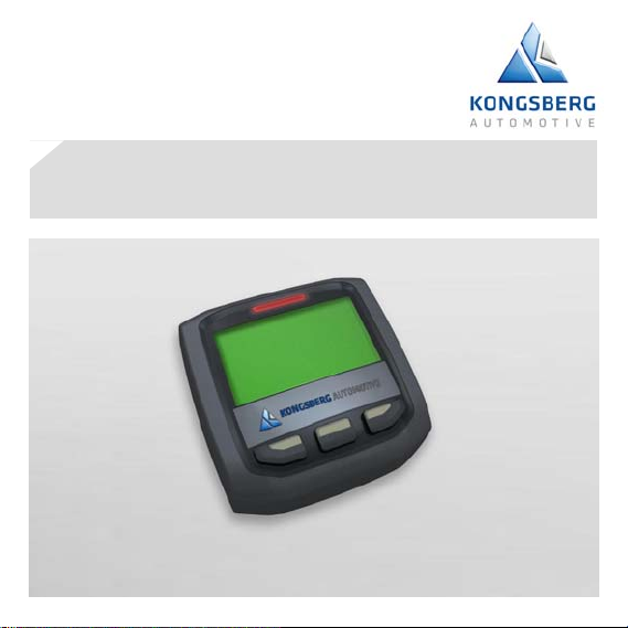
KAntrak™ 1700

Buffer Page
Hard covers must be printed
on top side only

Gem Application User's Guide
Thank you for choosing the KAntrak™ 1700 display.
These pages provide a brief introduction to the KAntrak™ 1700
Generic Engine Monitoring (GEM).
For more information please see the web site:
http://www.kongsbergautomotive.com/
Section/Contents Page
1. Menu Browsing.................................................................. 2
2. Display Modes ................................................................... 3
3. Settings Menu.................................................................... 8
4. Supported Parameters..................................................... 13
page 2
1. Menu Browsing
The KAntrak™ 1700 unit has only three(3) buttons for different
features selection. For that reason a dynamic style menu system
has been implemented.
During normal operation, the buttons have no specific functions.
When pressing any button once, a dynamic pop-up menu
appears. The menu contains some functions icons aligned above
the associated button. The user selects the required function from
the displayed menu. After a few seconds, the menu will be
hidden.

page 3
2. Display Modes
The GEM application is used to display live parameters and
diagnostic trouble codes available on the J1939 bus. By pressing
the button the user can scroll through the available parameters
on the vehicle's network. A complete list of supported parameters
are listed into the Supported Parameters section.
At any time in any display mode, the user can select the tool
to access the setting menu and change the current display mode.
See Settings Menu section.
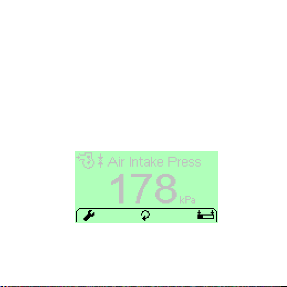
2.1 Single Screen
This mode is used to monitor one parameter at a time. The
screen also displays the associated parameter icon, the
description, the units and a bar graph.
page 4
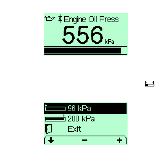
2.1.1. Bar graph Limits adjust
The Single Screen mode has a special function for bar graph
limits minimum and maximum adjustment. This can be done by
selecting the related parameter and then pressing the
button. The unit should now display the bar graph limits adjust
mode. Use +/- for adjustment and select Exit when finished.
page 5
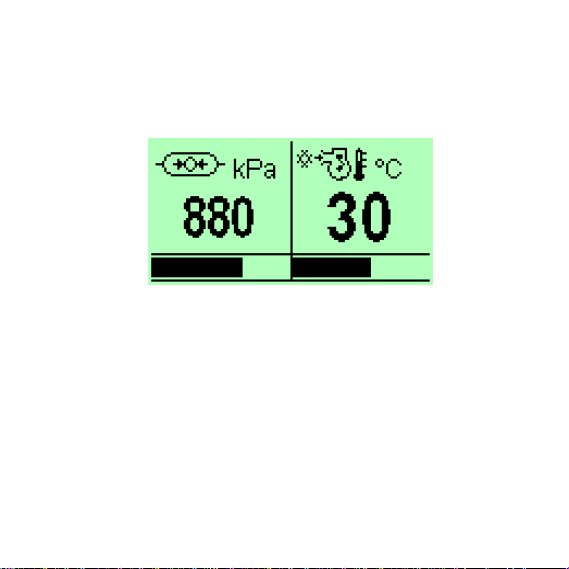
2.2 Dual Screen
The Dual Screen mode is used to monitor two parameters at a
time. The screen also displays the associated parameter icon and
units.
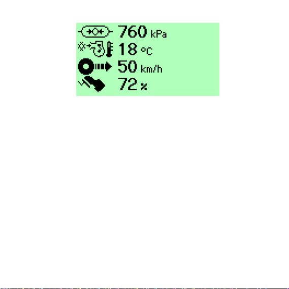
2.3 Multi Screen
The Multi Screen mode is used to monitor a list of four(4)
parameters selected by the user. Every item is listed with its
associated icon and units.
page 6
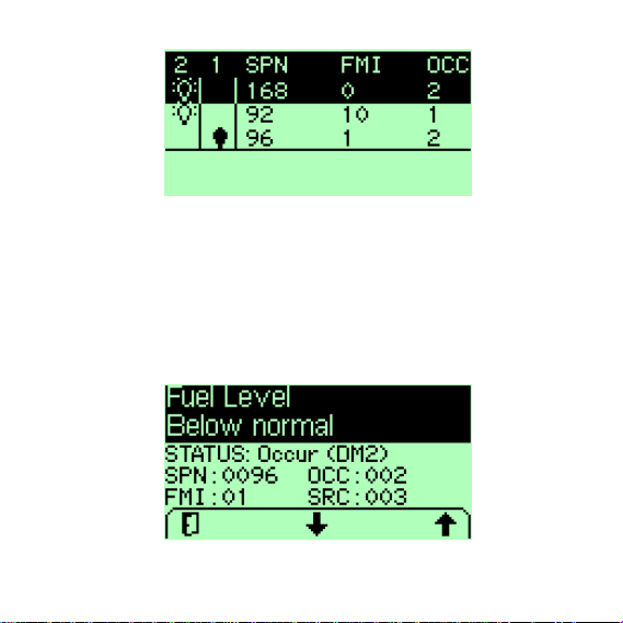
2.4 DTC Screen
The DTC Screen mode is used to display Data Trouble Codes
according to SAE J1939-73. The main screen displays all vehicle
active faults (DM1) and occurs faults (DM2). A bright bulb means
that the current fault is active while a dark bulb means that the
current fault has occured. The header contains the total
active/inactive faults, the associated SPN and FMI and the
numbers of occurances as well.
page 7
2.4.1. DTC Detailed info
For a given DTC, the user may select the ?function from the
menu. A detailed screen of the selected DTC including the SPN
description (Header), the FMI Description (Header), the fault
status (Status), the SPN Number (SPN), the FMI Number (FMI),
the total number of occurrences (OCC) and the related node
source address (SRC) will then appear.

page 8
3. Settings Menu
3.1 Display Mode
This setting is used to select the current display mode: Single,
Dual, Multi or Dtc. Display modes are explained into the section 2.
3.2 Language
The user can select various supported languages for interface
display.
3.3 Fuel Level Source
With Input mode selected, the device reads the fuel level signal
from the discrete sensor input. In this mode, the local information
is also broadcasted on the J1939 network to other nodes.

page 9
In Network mode, the device reads the fuel signal from the
associated PGN on the J1939 network.
3.4 Alarm Output
When enabled the external alarm device is turned on when a new
active fault (DM1) occurs. The alarm is turned off when all new
active faults have been acknowledged. In Disable mode, the
external device is never activated.
3.5 Demo Mode
By enabling this option, the users can test the unit even though is
not connected to the vehicle network. The network feed is
replaced by a simulation lead that allows the user to display every
supported SPNs. Moreover some Data Trouble Codes (DTC) are
also generated. This is disabled by default at power on.
3.6 Tier4 Popout Mode
This option enables pop-up monitoring of the selective catalytic
reduction (SCR) parameters available in J1939. When enabled,
any status change will appear in a pop-up window even if the
main window does not monitor the TIER4 parameters.

page 10
3.7 Contrast /Backlight
Contrast and backlight commands according to the user's
preferences.
3.8 Units
The system supports many combinations of units depending on
the user's preferences. Distance, Pressure and Volume units
could be selected independently. Default settings correspond to
all other measurements units.
3.9 Faults Clear
This submenu is used to send a request to every modules on the
vehicle to clear all occured faults (DM2).

page 11
3.10 Fuel Tank Calibration
This submenu is related to the discrete fuel input calibration. By
doing the calibration sequence, the user can calibrate the fuel
sender response for any custom tank in three(3) points. The best
way to do this is to start with an empty thank and fill it with fuel
during the process. The bargraph level represents the resistance
signal value as read from the discrete input. The response profile
may be different according to the sender characteristics.

page 12
3.11 Factory settings
This is intended to turn the unit back to the original factory
settings. All current setttings will be lost.
page 13
4. Supported Parameters
Supported parameters as defined into SAE J1939-71
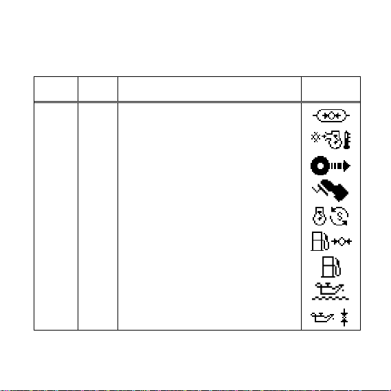
SPN # PGN # Description Icon
46 65198 Pneumatic Supply Pressure
52 65262 Engine Intercooler Temperature
84 65265 Wheel-Based Vehicle Speed
91 61443 Accelerator Pedal Position 1
92 61443 Engine Percent Load At Current Speed
94 65263 Engine Fuel Delivery Pressure
96 65276 Fuel Level 1
98 65263 Engine Oil Level
100 65263 Engine Oil Pressure

page 14
SPN # PGN # Description Icon
102 65270 Engine Intake Manifold #1 Pressure
105 65270 Engine Intake Manifold #1 Temperature
106 65270 Engine Air Inlet Pressure
107 65270 Engine Air Filter 1 Differential Pressure
108 65269 Barometric Pressure
109 65263 Engine Coolant Pressure
110 65262 Engine Coolant Temperature
111 65263 Engine Coolant Level
114 65271 Net Battery Current
115 65271 Alternator Current
127 65272 Transmission Oil Pressure
page 15
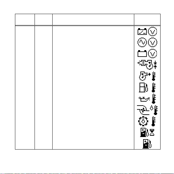
SPN # PGN # Description Icon
158 65271 Keyswitch Battery Potential
167 65271 Charging System Potential (Voltage)
168 65271 Battery Potential / Power Input 1
172 65269 Engine Air Inlet Temperature
173 65270 Engine Exhaust Gas Temperature
174 65262 Engine Fuel Temperature 1
175 65262 Engine Oil Temperature 1
176 65262 Engine Turbocharger Oil Temperature
177 65272 Transmission Oil Temperature
183 65266 Engine Fuel Rate
184 65266 Engine Instantaneous Fuel Economy

page 16
SPN # PGN # Description Icon
185 65266 Engine Average Fuel Economy
190 61444 Engine Speed
191 61442 Transmission Output Shaft Speed
246 65255 Total Vehicle Hours
247 65253 Engine Total Hours of Operation
441 65164 Auxiliary Temperature 1
512 61444
Driver's Demand Engine - Percent
Tor
q
ue
513 61444 Actual Engine - Percent Torque
517 65256 Navigation-Based Vehicle Speed
523 61445 Transmission Current Gear
524 61445 Transmission Selected Gear

page 17
SPN # PGN # Description Icon
975 65213 Estimated Percent Fan Speed
1032 65201 Total ECU Distance
1081 65252 Engine Wait to Start Lamp
1387 65164 Auxiliary Pressure #1
1761 65110 Catalyst Tank Level
1762 61448 Hydraulic Pressure
3031 65110 Catalyst Tank Temperature
3241 64948
Aftertreatment 1 Exhaust Gas
Temperature 1 (upstream)
3245 64947
Aftertreatment 1 Exhaust Gas
Tem
p
erature 3
(
downstream
)
3697* 64892 Particulate Trap Lamp Command
3700*64892
Particulate Trap Active Regeneration
Status

page 18
SPN # PGN # Description Icon
3701*64892 Particulate Trap Status
3703*64892
Particulate Trap Active Regeneration
Inhibited Due to Inhibit Switch
3719 64891 Particulate Filter 1 Soot Load Percent
3720 64891 Particulate Filter 1 Ash Load Percent
(*) See section 4.1
Other manuals for KAntrak 1700
1
Table of contents
Other Kongsberg Monitor manuals


