Kongsberg KAntrak Series User manual

GEM Manual
GEnEric EnGinE Monitor (GEM)
tiEr 4 upGradE
USER GUIDE
The Engine Monitor
Engine Monitor

page 2
What you should have
(clockwise from top left):
• Mountingtemplate/Packinglist
• TheEngineMonitorUserManual
• Frontmountingkit(4xstuds/nuts)
• TheKAntrak™2700/2710Display
Before you start - what you should have
plus
Other Engine Monitor accessories
optionally available (clockwise from
top left):
• TrunnionMountingBracket(PartNo.930293)
•ProtectivePushonFrontCover
(PartNo.165271)
• BehindDashMountingKit(PartNo.900061)
• Power/CANHarness(PartNo.510623)
• Power/CAN/GPSharness(PartNo.510626)
(not shown)

1.TheEngineMonitorUserManual
ThankyouforchoosingtheEngineMonitor.
These pages provide operating instructions
fortheEngineMonitorwhichdisplaysJ1939
orJ1587-compatibleengine/transmission
data.
Pleasereadthroughtheguidebeforeuse.
TheEngineMonitoruser-congurable
application software creates graphical
instrument clusters to display parameters
and alarms - providing users with a time-
saving solution for introducing equipment
incorporating higher degrees of electronic
displayandcontrol.
We hope you will be very happy with this
product and have many years of trouble-
freeoperation.Ifyouhaveanyproblemsor
ideas for improvement then we would like
tohearfromyou.
Formoreinformationpleasecontact
usat:[email protected]
website:www.kongsbergautomotive.com
Section/ContentsPage
2.UnderstandingTheEngineMonitor
3.GettingStarted
4.SoftKeys
5.TheTriDisplay
6.TheQuadDisplay
7.TheUniDisplay
8.DataParametersMonitored
9.ActiveandStoredAlarmLists
10.CongurationMenu
11.Pop-UpMessagesandWarnings
12.Tier4Pop-UpMessagesandWarnings
13.AdjustingLightingandContrast
14.PreferredScreenStore
15.KeypadLock
16.ConnectorPin-Out
17.TypicalJ1939WiringTopology
18.Installation
19.MaintenanceandTroubleshooting
20.TheKAntrak™Platform
21.SoftwareDevelopment
22.Glossary
23.ImportantSafetyandLegalInformation
page3
4
6
7
8
11
12
13
18
20
26
27
28
29
29
30
32
33
35
36
37
38
39

4
6
7
8
11
12
13
18
20
26
27
28
29
29
30
32
33
35
36
37
38
39
2.UnderstandingTheEngineMonitor
TheEngineMonitorsoftwarerunsonaKAntrak™display(seesection19forfurtherdetailson
theKAntrak™platform)withvesoftkeys,providingaexibleandintuitiveHuman-Machine
Interface(HMI).The5softkeysaccessagraphicalmenustructurethatusesstandardandeasily-
understoodiconstoindicatethekey’scurrentfunction.Thisenablestheoperatortoselectthe
requiredengine/transmissiondataanddisplayitinthefollowingformats:
•Analoguegauges
•Digitalvalues
•Historicaltrendgraphs
•Currentandstoredalarmmessages
Additionally,variousdiagnosticscreensareavailable,allowingdetailedinvestigationoftheengine
andtransmissiondatastream.TheunderlyingstructureoftheEngineMonitoranditsinteraction
withthesoftkeysmaybeunderstoodbyFigure1.ByaccessingtheCongurationmenu,users
cancustomisesomeofthedisplayeddatatoshow,forexample,metricorimperialunits,and
variousparameterssuchasthefull-scalereadingofgauges.
page4

Understanding The Engine Monitor - continued
TheEngineMonitorpresentsacontextdependent‘buttonbar’abovethepush
buttonsifanykeyfrom1to4ispressedfromlefttoright-itdisappearsafter5secondsof
inactivity.This‘toplevel’buttonbarshowsthebasicstructureoftheEngineMonitor:
page5
Key1: Key2: Key3: Key4: Key5:
TriDisplay,or
Main Engine
Display.Repeat
presses
cycle the fuel
computer
through various
modes:
QuadDisplay
(user
congurable).
Repeat presses
cycle the
display around
3differentquad
view options:
Uni Display
showing
data history
(congurable).
Repeat presses
cycle display
through available
parameters:
ActiveAlarm
Display.Holding
the key brings
up Stored
Alarms:
Contrast
andLighting
adjustment,
or-ifheldfor3
seconds - the
Conguration
menu:
Figure 1

3.GettingStarted
Whenpowerisappliedtothedisplay,astart-upscreendisplaysforapproximately7seconds
whilethedisplayperformsaselftest.Ifthedisplaymakesa‘bleep-ing’soundforlongerthan1
second,self-testhasfailed. Users can attempt to rectify the fault by restoring factory defaults (see
Congurationmenu/section10fordetails);ifthefaultpersists,contactyoursupplierforguidance.
Afterthestart-upscreendisappears,theEngineMonitorstartsdisplayingreadingsonitsvirtual
gaugesifitisconnectedtoanactivesourceofdata.TheEngineMonitordisplaysthe‘main
enginedisplay’ortri-screenoninitialstart-up,butnotethatafterusethischangestothescreen
thatwaslastdisplayed(seePreferredScreenStore/section13fordetails).TheEngineMonitor
displaymodesaredetailedinthefollowingsections.
page6
4.SoftKeys
TheEngineMonitor’ssoftkeyssimplifytheoperatorinterface.Inuse,theEngineMonitordisplays
a‘buttonbar’directlyabovethesoftkeyswhenanyoftherst4keys(keys1to4,startingfrom
theleft)arepressed-withiconsrepresentingthecurrentfunctionofeachkey.Figure2.shows
thetoplevelbuttonbar,withicons1to4representingthegaugesandalarmsavailable,andicon
5an‘exitdoor’.Repeatpressesofthesebuttonstogglesaroundthedisplayoptionsavailable.
Thebuttonbarwilldisappearafterapproximately5secondsifnofurtherkeysarepressed.
Figure 2. The Engine Monitor’s top level
button bar menu:
Key 1: Pages icon indicating that further
presses cycle through options for the
screen being viewed (in this instance fuel
computer modes for the main engine
display)
Key 2: Quad Display mode
Key 3: Uni Display mode
Key 4: Alarm Display mode
Key 5: Exit door
page7

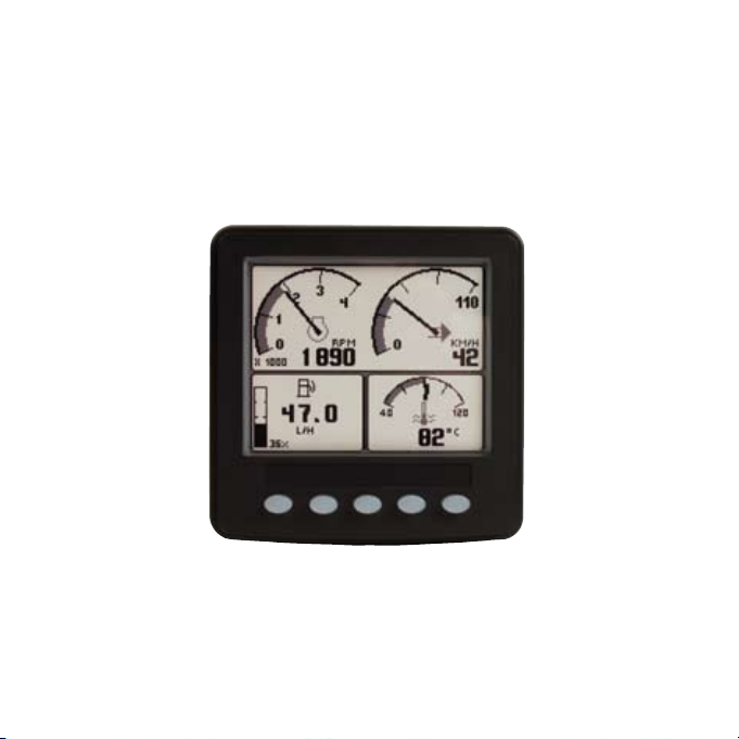
5.TheTriDisplay
ThisEngineMonitordisplaymodeprovidesthreeindependentwindows,andisintendedtoshow
themostfrequentlyaccessedvehicledata(RPM,speed,temperatureandfuel).ToselectTri
Display,pressanyoftherst4keystoshowthetoplevelbuttonbar,andthenpresskey1(the
left-handkey).Theparameterdisplayedinthetoprightgaugeisuserdened,tochangethe
displayeddatapresskey5whenthebuttonbarisvisibleandthenkeys1and2tocyclethrough
theavailableparameters.Alsothedatadisplayedinthefuelcomputerwindow(Bottomleft
window)maybechangedbyrepeatedpressingofkey1,Thisisexplainedinmoredetailinthe
followingpages.Also,attributessuchasunitsandscalesmaybechangedviatheConguration
menu(Seesection10fordetails).
Figure3.1.TriDisplay,accessedviakey1.
Note.Metricunitsareshownasdefault,butothersmaybe
selectedviatheCongurationmenu.
Thetopwindowshows2analoguegauges;
EngineRPMandSpeed(maximumRPM
andspeedmaybesetviatheConguration
menu).Ifspeeddataisnotavailabletheright
handgaugewilldisplayengineoilpressure.
The bottom right window shows coolant
temperature.Thebottomleftwindowdisplays
thefuelcomputer.
It is also possible to display speed derived
fromaGPSmodulewithanNMEA0183
output-interfacedviathedisplay’sRS232
port (contact your Engine Monitor supplier for
furtherinformation).
page8
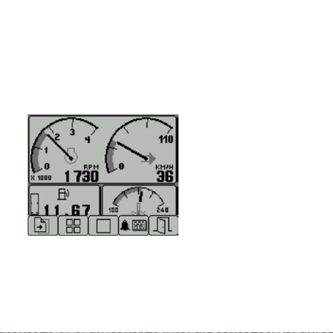
5.TheTriDisplay(FuelComputerModes)
Figure3.2.Afuelcomputer
display.
Note.Metricunitsareshownas
default,butothersmaybe
selectedviatheconguration
menu.
Below is the list of parameters that can be displayed in the fuel computer window in alphabetical
order:
Distance Remaining:CalculatedifFuelTankCapacityissetandFuelRate,VehicleSpeed
andFuelLevelareavailable[Distance]
Fuel Level:Ifavailable[Volume]
Fuel Rate: Ifavailable[Volume/Hour]
Fuel Remaining:CalculatedifFuelTankCapacityissetandFuelLevelisavailiable[Volume]
Instantaneous Fuel Economy:CalculatedifVehicleSpeedandFuelRateareavailable
[Distance/Volume]
Total Engine Hours:Ifavailable[Hours]
Total Vehicle Distance:Ifavailable[Distance]
page9
The lower left display window provides access to the fuel computer
dataandalsoshowsfueltanklevel.Uponpressingkey1thefuel
computerishighlighted,whenhighlightedvariousdatacanbe
displayedbyrepeatpressingofkey1.Whenrstselectedasmall
iconwillalsoappearinthecentreofthescreenwiththetext“Hold
Reset”.Holdingkey1atthistimewillperformaTripReset.After2
seconds of no key presses the fuel computer will go back to normal
andtheiconwilldisappear.
DataAvailableissimilartoanautomotivein-carfuelcomputer.

5.TheTriDisplay(FuelComputerModes)-continued
page10
Trip Distance:CalculatedsincelastTripResetifTotalVehicleDistanceisavailiable
[Distance]
Trip Engine Hours: CalculatedsincelastTripResetifTotalEngineHoursisavailiable
[Hours]
Trip Fuel: CalculatedsincelastTripResetifTotalFuelUsedisavailiable[Volume]
Trip Fuel Economy:CalculatedsincelastTripResetifTotalFuelUsedandTotalVehicle
Distanceareavailable[Distance/Volume]
Trip Fuel Rate:CalculatedsincelastTripResetifTotalEngineHoursandTotalFuelUsedare
available[Volume/Hour]
Note.ATripResetaffectsallreset-ablefuelcomputerparametersandcanbeperformedby
holdingkey1whentheHoldReseticonappears.Theiconappearsforapproximately2seconds
whenthefuelcomputerwindowisrstselected.SettingTotalFuelTankDataandFuelTank
ResetisperformedviatheCongurationmenu.

6.TheQuadDisplay
QuadDisplaymodeprovides4gauges.Toselectit,pressanyofthekeys1to4toshowthetop
levelbuttonbarandthenkey2.Repeatpressesofkey2cyclethedisplayaround3separate
quadscreens:4digitalgauges,4analoguegaugesand4alternativeanaloguegauges.All
12gaugesmaybeselectedandconguredbyusers,providingasimplemeansofcreating
application-specicviewsofenginedata.Gaugesareselectedviaquaddisplay’s‘adjustmode’,
bypressingkey5(notedbyanarrowicon)whentheEngineMonitorisrunningquaddisplayand
thebuttonbarisvisible.Inadjustmode,correspondingkeypressescyclethedisplaythrough
availableparameters(listedinsection8).Theselectedcongurationisstoredevenwhenpower
isremoved;adjustmodeisexitedbypressingkey5.
Figure 4. Top row: the 3 default displays available in
quad-display, and adjust mode (right) which allows
users to select the gauges displayed.
Note. If a parameter is not available from the engine/
transmission, it will not be possible to select it. If the
parameter becomes unavailable while in view, ‘- - -‘ is
displayed.
page11
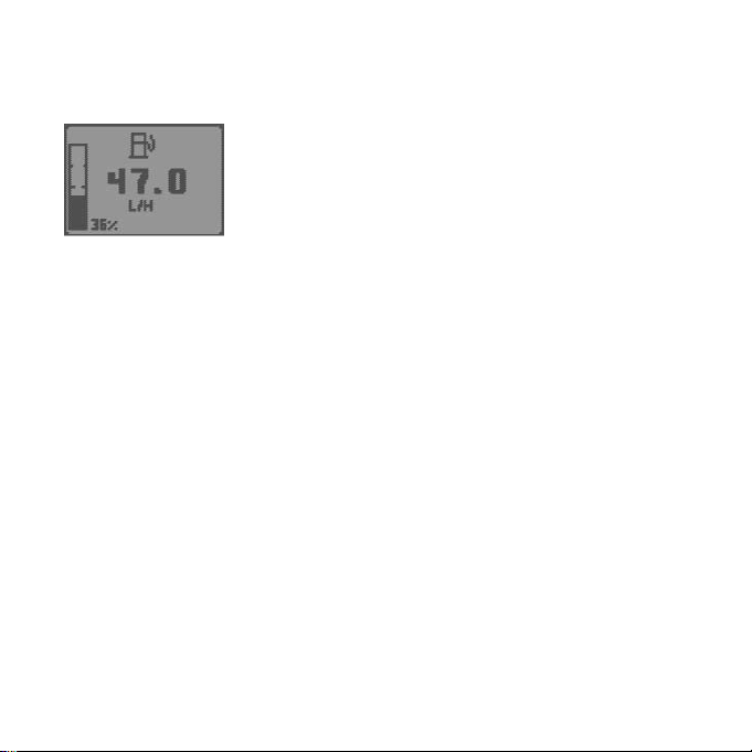
7.TheUniDisplay
Figure 5. Example graph display plotting battery
potential switched.
Note. If a parameter is not available from the
engine/transmission, it will not be possible
to select it. If the parameter becomes
unavailable while in view, ‘- - -’ is displayed.
page12
The Engine Monitor’s Uni Display mode
plots data history in one large window - in
anX-Ygraphformatsimilartoapenplotter.
This mode is selected by pressing any of
therst4keystoshowthetoplevelbutton
barandthenkey3.
Dataisshowningraphform,withthemost
recentdatascrollingfromrighttoleft.The
viewedtimerangemaybeadjustedinthe
Congurationmenufrom2minutesto8
hoursinsixsteps.Maximumandminimum
valuesoftheYaxis(thereadingspan)are
adjustedautomaticallytogiveanoptimum
viewofdata.Theparameterdisplayedis
selectablebyrepeatedlypressingkey3
whileintheUniDisplaymode.
The parameters that may be displayed are
listedinsection8.

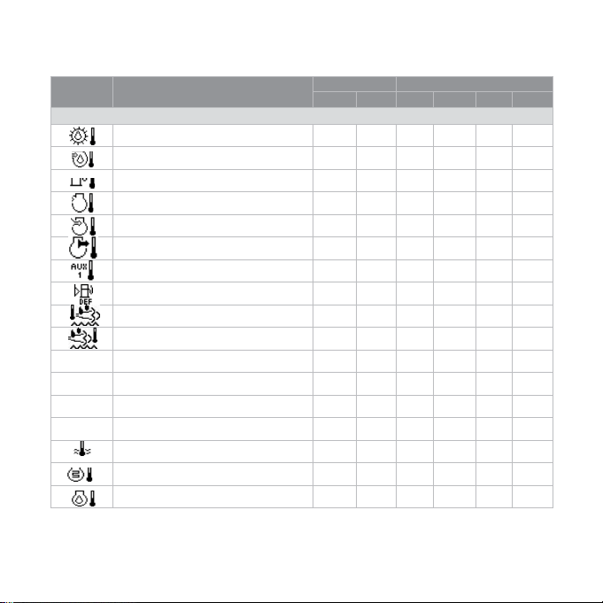
8.DataParametersMonitored
ThistableliststheengineandtransmissionparametersthataremonitoredviatheJ1939and/or
theJ1587datalinks.TheparameterscanbedisplayedbytheEngineMonitorinuser-congurable
TriDisplay,QuadDisplayorUniDisplaymodes(√ indicatestheparametermaybeselected).DB
isanabbreviationfortheEngineMonitor’sinternaldatabase,whichstoresalldatatransmitted
fromtheengine/transmission.Thecompletedatabaselistcanbeaccessedonthedisplayviathe
Congurationmenu.
Abbreviations:Theunits‘MPG’and‘Gal’denoteUSgallons.Fornon-USImperialgallons
(UK,Canada,etc)theunitsaredenotedas‘IMPG’or‘IGal’.N=nautical.KTS=knots
Note.Ifaparameterisnotavailable,itwillnotbepossibletoselectit.Iftheparameterbecomes
unavailablewhileinview,‘---‘isdisplayed.
Icon Parameter Datalinks Screens
J1939 J1587 Tri Quad Uni DB
ELECTRICAL(VoltsorAmps)
ElectricalPotential √ √ √ √ √ √
BatteryPotentialSwitched √ √ √ √ √ √
NetBatteryCurrent √ √ √ √ √ √
AlternatorPotential √ √ √ √ √ √
AlternatorCurrent √ √ √ √ √ √
page13

page14
Icon Parameter Datalinks Screens
J1939 J1587 Tri Quad Uni DB
FUEL(L,Gal,lGal)or(L/h,Gal/hIGal/h)or(km/L,MPGorIMPG)
FuelRemaining √ √ √ √
FuelRate √ √ √ √ √ √
InstantaneousFuelEconomy √ √ √ √
TripFuelEconomy √ √ √ √
TripFuel √ √ √ √
TripFuelRate √ √ √ √ √
None TotalFuelUsed √ √ √
None FuelLeakage1 √ √
None FuelLeakage2 √ √
DISTANCE(km,MilesorNmiles)
Distance Remaining √ √ √ √
Trip Distance √ √ √ √
TotalVehicleDistance √ √ √ √
SPEED(RPM,km/h,MPHorKTS)
None Input Shaft Speed √ √ √
None Output Shaft Speed √ √ √
Engine Speed √ √ √ √ √ √
None Turbo1Speed √ √ √
None Engine Desired Operating Speed √ √
NavigationWheelBasedVehicleSpeed √ √ √ √ √
8.DataParametersMonitored-continued

page15
Icon Parameter Datalinks Screens
J1939 J1587 Tri Quad Uni DB
PRESSURE(kPa,PSIorbar)
FuelDeliveryPressure √ √ √ √ √ √
BarometerPressure √ √ √ √ √
AuxiliaryPressure1 √ √ √ √
BoostPressure √ √ √ √ √ √
AirInletPressure √ √ √ √ √
AirFilter1DifferentialPressure √ √ √ √ √
None InjectorMeteringRail1Pressure √ √ √
None InjectorMeteringRail2Pressure √ √
CoolantPressure √ √ √ √ √ √
EngineOilPressure √ √ √ √ √ √
TransmissionOilPressure √ √ √ √ √ √
None ClutchPressure √ √ √
None AirStartPressure √ √ √
None InjectionControlPressure √ √ √
TIME (h)
TotalEngineHours √ √ √ √
TripEngineHours √ √ √ √ √
None ServiceHours √
8.DataParametersMonitored-continued
page16
Icon Parameter Datalinks Screens
J1939 J1587 Tri Quad Uni DB
TEMPERATURE(ºCorºF)
Transmission Oil Temperature √ √ √ √ √ √
Turbo Oil Temperature √ √ √ √ √
FuelTemperature √ √ √ √ √
IntakeManifold1Temperature √ √ √ √ √ √
AirInletTemperature √ √ √ √ √
ExhaustGasTemperature √ √ √ √ √ √
AuxiliaryTemperature1 √ √ √ √ √
CatalystTankTemperature √ √ √ √
Upstream Gas Temperature √ √ √ √
Downstream Gas Temperature √ √ √ √
None EngineECUTemperature √ √
None ExhaustGasPort1Temperature √ √
None ExhaustGasPort2Temperature √ √
None Turbo1CompressorInletTemperature √ √
EngineCoolantTemperature √ √ √ √ √ √
Engine Intercooler Temperature √ √ √ √ √
EngineOilTemperature1 √ √ √ √ √ √
8.DataParametersMonitored-continued
*
*
*
* IndicatesGEM4Tier4Updgrades

Icon Parameter Datalinks Screens
J1939 J1587 Tri Quad Uni DB
PERCENTAGE(%)
CoolantLevel √ √ √ √ √
EstimatedPercentFanSpeed √ √ √ √
DriversDemandPercentTorque √ √
ActualEnginePercentTorque √ √ √ √
TorqueUseatRPM √ √ √ √ √
SootLoadPercent √ √ √ √
AshLoadPercent √ √ √ √
CatalystTankLevel √ √ √ √
FuelLevel √ √ √ √
AccelerationPosition √ √ √ √ √
None ThrottlePosition √ √ √
EngineOilLevel √ √ √ √ √
MISCELLANEOUS
None TorqueConverterLock-UpEngaged √ √
CurrentGear √ √ √ √
Selected Gear √ √ √ √
None CANTXDisable √ √
* IndicatesGEM4Tier4Updgrades
Note.Thislistiscurrentatthetimeofgoingtopress,newparametersarecontinuallybeingadded
-thelatestlistmaybefoundinthelatestdatasheet(availableviawww.kongsbergautomotive.com).
page17
8.DataParametersMonitored-continued
*
*
*
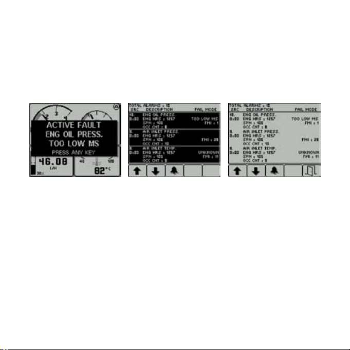
9.ActiveandStoredAlarmLists
Activealarms.Whenanactive/currentalarmisreceived,aashingpop-upwindowappears
overlaidonthecurrentscreeninuse,showingdetailsofthecurrentalarm.Whenanactivealarm
isreceived,theEngineMonitoractivatesitsinternalsounder,andtheexternalalarmoutputon
Pin11(ifavailableontheKAntrak™youhavechosen).
Figure 6. Example alarm message, plus alarm list screens showing unacknowledged conditions (black
background) and acknowledged alarms (grey background). After acknowledgement, the exit key (open
door icon) becomes active. J1939-standard abbreviations are used wherever possible, Note. “MS” = Most
Severe, “MOD”= Moderately Severe and “LS” = Least Severe.
Thealarmlistisaccessedbypressinganykeywhileanalarmpop-upisdisplayed,orby
pressinganyoftherst4keystoshowthebuttonbar,andthenkey4.Thisscreendisplays
allcurrentactivealarms;whenentered,Pin11ExternalAlarmOutputisdeactivated(ifthe
functionisavailable).Alarmsnotyetacknowledgedareshowningreyonblack.Alarmsalready
acknowledgedareshowninblackongrey.Ifenginehoursdataisavailable,thelistindicates
whenthealarmwasinitiated.
page18
9.ActiveandStoredAlarmLists-continued
Whenrstenteringthescreen,thelistautomaticallydisplaysthemostrecentalarm.Thelist
canbescrolledusingkeys1and2.Thisscreencannotbeexiteduntilallalarmshavebeen
acknowledgedbypressingkey3.Alarmmessagesareautomaticallyclearedfromthelistwhen
nolongerreceivedbytheEngineMonitor.
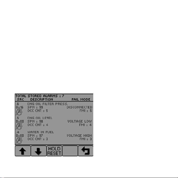
Storedalarms.Alarmsstoredbyengine/transmissionECU’s(i.e.notactiveorcurrentbutold/
historicalalarms)maybeviewedbypressingandholdingkey4whiletheactivealarmlist
screenisvisible.Onentrytothispage,theEngineMonitorsendsadatarequesttotheengine/
transmission.Theengine/transmissionsendsthestoredalarmdatatotheEngineMonitor,which
isdecodedanddisplayedinasimilarfashiontoactivealarms.TheEngineMonitordisplaysan
errormessageifthereisnoresponsefromtheengine/transmission.Iftheengine/transmission
supportstheerasureofstoredalarms,theymaynowbeerasedbyholdingkey3.
Figure 7. An example Stored Alarm List
screen.
page19
Table of contents
Other Kongsberg Monitor manuals


