Konig VID-TRANS10SKN User manual
VID-TRANS10SKN
2.4GHZ WIRELESS AUDIO/VIDEO SYSTEM
OWNER’S MANUAL

■Important-Safety Precautions
This device of which operation is subject to the following two conditions
(1) This device may not cause harmful interference, and
(2) This device must accept any interference received, including interference
that may cause undesired operation.
• To prevent fire or shock hazard, do not expose this device to rain or
moisture.
• Do not use near a bathtub, washbowl, kitchen sink, or laundry tub, in a wet
basement, or near a swimming pool.
• To avoid electrical shock, do not open this device.
• This device should be operated to use only the power supply included with it
or provided as an accessory.
• Do not overload wall outlets and extension cords as this can result in the
risk of fire or electrical shock.
• Do not attempt to service this device yourself. Refer servicing to qualified
personnel only.
Caution: Changes or modifications not expressly approved by the Party
responsible for compliance could void the user’s authority to operate the
equipment.
Note:
This equipment has been tested and found to comply with the limits for a
class B digital device, pursuant to Part 15 of the FCC Rules, or BZT and
CE EMC directive. These limits are designed to provide reasonable
protection against harmful interference in a residential installation. This
equipment generates, uses and can radiate radio frequency energy, if not
installed and used in accordance with the instruction, it may cause harmful
interference to radio communications. However, there is no guarantee that
interference will not occur in a particular installation. If this equipment does
cause harmful interference to radio or television reception, which can be
determined by turning the equipment off and on, the user is encouraged to
try to correct the interference by one or more of the following measures:
o Reorient or relocate the receiving antenna.
o Increase the separation between the equipment and receiver.
o Connect the equipment into an outlet on a circuit different from
-1-
o that to which the receiver is connected.
o Consult the dealer or an experienced radio/TV technician for help.
A. Checking Contents of Box
Checks to make sure that all of the items shown as below are included with
your 2.4 GHz Wireless Video Sender System. If something is missing, please
contact your dealer as soon as possible.
1. Transmitter 2283T ×1
2.Receiver 2283R X1
3. Power adapter
(230VAC to 9VDC) or (120VAC to
9VDC) DC in Jack 9V 400mA
X2
4.Cable (optional)
RCA to RCA connector A/V cable or
RCA to SCART connector. (One for
transmitter, one for receiver)
×2
5. IR extender to connect to
(optional)
transmitter's rear panel
X1
6.Owner’smanual ×1
-2-

B. Introduction to 2.4GHz Wireless AV Link
This sender system is a wireless audio/video sender that uses advanced
wireless communication technology to deliver consistently sharp audio and
video up to 100 meters away. By transmitting at a very high frequency (2.4
GHz), it avoids the crowded 900 MHz band used by many cordless telephones
and other wireless audio/video transmitters. It’s superior quality is due to wide-
band FM rather than AM signal modulation. Circular polarized high-gain
directional transmitting and receiving antennas are used to minimize
interference from unwanted signals and maximize the signal range.
It also integrates an UHF remote control extender to allow you to control the
audio or video source from another room using your existing remote controller.
Using sender system, you can enjoy greater convenience and security in many
ways:
General Application
• Watch the movie you rent on any TV in house without moving your VCR,
laser disc player or running messy cables.
• Watch cable or satellite programs on any TV in house.
• Listen to stereo-quality music from your receiver on any powered speakers
inside or outside the house.
• Uses multi-receivers for broadcasting to numerous TV sets in other rooms.
• Show computer images on a remote TV. (Additional equipment required)
Safety & Security Application:
• Applies as a wireless security system.
• Monitor your sleeping baby, playing children, the elderly, or the disabled on
TV using your existing camcorder.
• See who is outside the door on TV through your camera or miniature CCD
camera.
• Monitors and records meeting from another room.
• And many more uses!
-3-
■ The Using Attention
1. The outlet of the power supply must have the same voltage as the local
area.
2. Be sure the transmitter and the receiver were connected to the equipment
correctly (e.g. Connect the transmitter to the VCR, and the receiver to the
TV).
3. When switch is off from transmitter or receiver, it needs to wait for a few
seconds in order to restart again.
4. Adjust antenna plate for least interference. (Adjustment cannot rotate
more than ±180°).
5. In most situations, one set of equipment has a better feature within 100
meter. When two equipment or more is used at the same time, used
different channels. But a transmitter can be used with several receivers at
the same time.
6. The channel selectors allow you to choose the channel for best feature
and least interference.
7. When the equipment is operating, please do not use a microwave oven
near by.
8. The remote control should face to the receiver (e.g. 2283R) IR remote
control window, and the transmitter (e.g.2283T) IR remote control window
(or IR extender) should face to the source A/V equipment. The IR remote
has to be within the standard distance.
-4-

C. Panel Controls and Features of Duplex Function
Type
The following illustrations show the names of each component,
button and switch connectors on the transmitter and receiver.
(e.g.2283T/R)
FRONT VIEW FOR TRANSMITTER AND RECEIVER
UHF antenna sends and Directional 2.4GHz
receives remote control antenna sends and
signal receives audio and
video signals
Channel indicator
lights must be set to
same number on both
transmitter and ceiver
(4 CH or 2 CH)
Power on/off switch
Channel selection button
use to find optimum Remote control window
reception, most select infrared passes through
same channel on both this to remotely control
transmitter and receiver audio/ video source
-5-
REAR VIEW FOR TRANSMITTER
REAR VIEW FOR RECEIVER
Channel select CH3
or CH4 (NTSC only)
RF output to TV
(e.g.2058R)
DC power input, connect
to power adapter (9VDC)
-6-
DC power input, connect
To power adapter (9VDC)
IR extender output port
Audio L in (white)
Audio R in (red)
Video in (yellow)
Audio L out (white)
Audio R out (red)
Video out (yellow)

D. Setting Up 2.4GHz wireless AV Link
To enjoy wireless video and audio, just connect the transmitter (2283T and all
the others) to whatever audio/video source you want to enjoy from another
location, and connect the receiver (2283R and all the others) to the TV, monitor
or powered speakers in that other location.
A/V link system is suggested to connect to following A/V equipment use:
-7-
Make sure the ON/OFF switch is in the cOFF fposition before connection.
■How To Transmit Audio/Video from Your VCR
1. Connect one set of audio/video (A/V) cables (RCA or SCART cable) to the
A/V jack of the transmitter (2283T) and to the A/V output jacks (RCA or
SCART connector) on the back of your VCR. If you use 2283T/R, Be sure
the yellow, red and white plugs match the yellow, red and white jacks on
both the VCR and the transmitter. If the VCR has only one output for audio
(mono sound only), connect the white plug to that single audio output and to
transmitter's AUDIO LEFT jack.
2. Plug one end of the power adapter into the back of the transmitter and the
other end into any 230-volt wall outlet (or 120-volt). Use only the adapter
provided.
3. If your VCR has only one set of A/V output jacks and you want to use it with
a nearby TV, connect 75ohm RF coaxial cable from the modulator signal
OUT port on your VCR to the RF IN port on your TV. (Note: In order to also
view cable programs on that TV, connect your incoming cable TV source to
the IN port of the VCR.)
4. Locate and orient the transmitter according to the section of this manual
titled "Orienting Units for Optimum Performance"for best performance of
transmitter.
-8-
Video sources:Audio sources:
VCR Compact Disk player or Changer
Set-top box (with A/V output) Stereo Receiver
Satellite Receiver Cassette Deck
Camcorder or Miniature CCD Camera Laser Disc Player
Cable
Digital decoder
DVD
Recommended TV
connection for
dual-output VCR’s
75 OHM COAXIAL CABLE
(must be purchased)
TV
RCA TO SCART CONNECTOR A/V CABLE
TO POWER OUTLET
LINE
IN
LINE
OUT1
LINE
OUT2
VCR
IN
OUT
TV ANT IN
TRANSMITTER
A/V IN
RF IN
+
12VDC IN
AUDIO
LEFT VIDEO
-
AUDIO
RIGHT
IR

■How To Transmit Audio/Video from Your Satellite Receiver
You can transmit audio/video either directly from your satellite receiver, or by
connecting them to your VCR. To transmit directly from your satellite receiver,
follow the instructions below.
1. Connect one set of audio/video (A/V) cables (RCA or SCART cable) to the
A/V jacks of the transmitter (2283T) and to the audio/video OUT jacks (RCA
or SCART connector) of the satellite receiver or laser disc player. If you use
2283T/R, Be sure the yellow, red and white plugs match the yellow, red and
white jacks on both the satellite receiver/laser disc player and the transmitter.
2. Plug one end of the power adapter into the back of the transmitter and the
other end into any 230-volt wall outlet (or 120-volt). Use only the adapter
provided.
3. If your satellite receiver or laser disc player has only one set of A/V output
(RCA or SCART connector) jacks, in this case, please connect 75ohm RF
coaxial cable from satellite receiver's modulator output port to TV RF input
terminal.
4. Locate and orient the transmitter according to the section of this manual
titled "Orienting Units for Optimum Performance" for best performance of
transmitter.
-9-
■How To Receive Wireless Audio/Video Signals on Your TV
There are two ways to receiver wireless audio/video signals on your remote
TV (TV in another location such as in bedroom, kitchen).
• Connect the receiver directly to the remote TV.
• Connect the receiver to a VCR, which is then connected to the TV.
If your TV has picture-in-picture capabilities, you can view any image
transmitted by sender, such as your sleeping baby, in a small inset picture
while enjoying other programming on the rest of the screen. Consult the
owner's manual of your TV for instructions on using these capabilities.
Connecting Receiver Directly to Remote TV
If your TV has A/V jacks, connect one set of A/V cables (RCA or SCART
cable) to the TV's A/V jacks and to the A/V output jacks on the receiver
(2283R). If you use 2283T/R, Be sure the yellow, red and white plugs match
the yellow, red and white jacks on both the TV and the receiver.
If the TV has only a single jack for audio input, connect the white plug to that
jack.
-10-
TRANSMITTER
RCA TO SCART CONNECTOR A/V CABLE
TO POWER OUTLET
SATELLITE RECEIVER
950-2050 MHz CABLE
75 OHM COAXIAL CABLE
(must be purchased)
A/V IN
RF IN
SCART TO SCART CONNECTOR A/V CABLE
IN
RF
OUT
SATELLITE
IN
12VDC IN
AUDIO
LEFT VIDEO
AUDIO
RIGHT
IR
TRANSMITTER
+
-
TEL
A
C POWER
TV
RECEIVER
A/V IN
RF IN
RCA TO SCART CONNECTOR A/V CABLE
AUDIO
LEFT +
VIDEO
-
AUDIO
RIGHT
TV
12VDC IN
■Connecting Receiver to Remote TV through VCR
This setup enables you to record transmitted audio and video on your remote VCR
and also enjoy the picture and sound on a remote TV at the same time.
1.Connect one set of audio/video (A/V) cables to the A/V output jacks of the
receiver (2283R) and to the A/V input jacks on your VCR
If you use 2283T/R, Be sure the yellow, red and white plugs match the yellow, red
and white jacks on both the receiver and the VCR. If the VCR has only a single
jack for audio input, connect the white plug to it.
2.If your TV has A/V input jacks, connect another set of A/V cables to the
TV's A/V input jacks and to the A/V output jacks on your VCR.
3.If your TV does not have any A/V input jacks, please connect a 75ohm coaxial
cable from the TV's antenna in (or RF in) to VCR's modulator output.
This feature is optional
4. Plug one end of the sender power adapter into the back of the receiver and the
other end into any 230-volt (or 120 volt) wall outlet. Use only the adapter
provided.
5. Locate and orient the receiver to best video and sound quality please according
to the section of this manual titled "Orienting Units for optimum Performance".
11
E. Orienting Units for Optimum Performance
This sender system should be placed on a flat, stable surface to prevent
damage to it from falling.
For optimum performance, both the audio/video and remote control antennas
should be carefully oriented as described below. In addition, to use the remote
extension feature, the transmitter itself must be specially oriented so it can relay
the converted remote control signal back to the audio/video source (see following
section titled "Using The Remote Control extension Feature"). For maximum
operating range, try to minimize the number of obstacles (e.g. your TV or other
electronics, large furniture) where between the transmitter and receiver units.
Orienting the Audio/Video Antennas
Sender broadcast their high-quality audio and video using directional antennas,
which must be oriented in certain configurations for best results. The antennas
have been designed to pivot and rotate in-almost any direction.
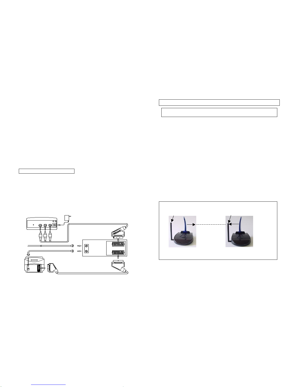
In most situations, the flat-pitted face of the antennas on both the transmitter and
receiver should be facing one another and perpendicular (at a right angle) to an
imaginary line drawn between the two units. Three examples are shown Fig-l, Fig-
2 and Fig-3. Since all homes are different, for optimum reception, additional slight
pivots or rotations may be necessary. If the transmitter and receiver are less than
10 feet apart, suggest keeping the antennas flat in their casings since the distance is
so short.
REMOTE ANTENNA REMOTE ANTENNA
CONTROL PITTED CONTROL PITTED
ANTENNA SIDE ANTENNA SIDE
TRANSMITTER RECEIVER
( Front View ) (Front View )
Fig-1: How to orienting the 2.4GHz audio and video antennas.
12
RECEIVER
RECEIVER
SCART TO SCART CONNECTOR A/V CABLE
TV ANT IN
75 OHM COAXIAL CABLE
(must be purchased)
TO POWER OUTLET
VCR
IN
OUT
LINE
IN
LINE
OUT
TV
A/V IN
RF IN
AUDIO
LEFT VIDEO
AUDIO
RIGHT
IR -
12VDC IN
+ RCA TO SCART CONNECTOR A/V CABLE
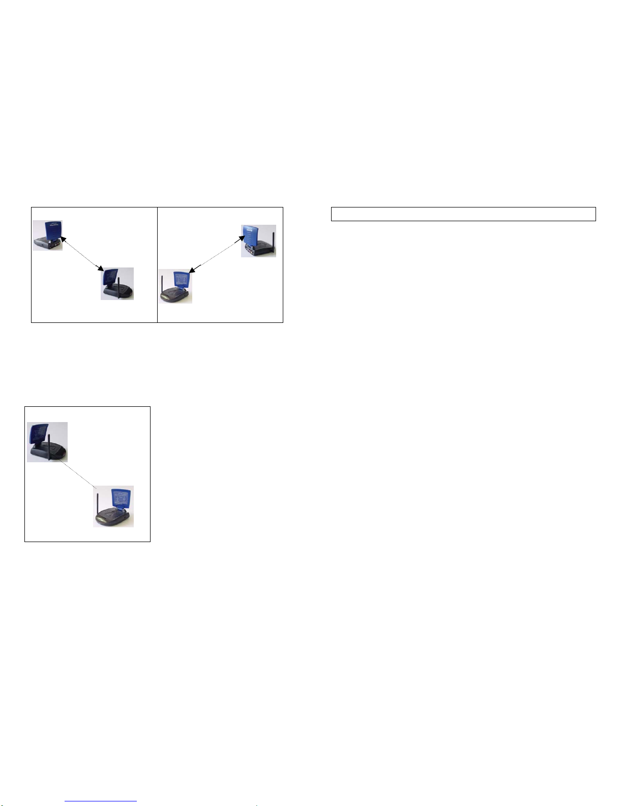
ANTENNA
PITTED
SIDE
ANTENNA
PITTED
TRANSMITTER SIDE
(Side View)
RECEIVER
(Side View)
ANTENNA
PITTED
SIDE
ANTENNA
PITTED RECEIVER
SIDE (Side View)
TRANSMITTER
(Side View)
Fig-2 Fig-3
Orienting the Remote Control Antennas
In order to obtain optimum performance of the remote control extender, the
remote control antennas should also be oriented at a right angle to an
imaginary line drawn between the transmitter and receiver units.
Fig-4: How to orienting the remote control antenna
-13-
F. Using the Remote Control Feature
This sender system not only allows you to send crisp audio/video from one
area to another, it also gives you the ability to control the source using your
existing remote control device. It converts the infrared (IR) signal emitted by
your remote control to a radio frequency (RF) signal in UHF band at the
receiver (e.g.2283R) and sends it back to the transmitter (e.g.2283T) where
the RF signal is converted back to the original IR signal and beamed to the
audio/video source.
There are two ways to get your source A/V equipment to be controlled by using
existing remote control through remote control feature:
1.To orient the transmitter unit, face to face the source A/V equipment, this
would allow the converted IR signal, which from transmitter IR remote control
window be able to send to the source A/V equipment(s) front panel.
2. Simply connect an IR extender from transmitter and locate this IR extender
near the source A/V equipment from panel.
Sometimes, it may be difficult or even impossible to orient the transmitter unit
such that it can be "seen" (means face-to-face) by the A/V equipment you
wish to control. Perhaps there is no good surface that allows for this or
perhaps you wish to control. Or perhaps you wish to remotely control A/V
equipment in different locations without re-orienting the transmitter. So, in
this case, to use in extender will be more convenient.
-14-
TRANSMITTER
REMOTE
CONTROL
ANTENNA
REMOTE
CONTROL
ANTENNA
A
NTENNA
If your remote control extende
r
is not working satisfactorily,
rotating the remote control so
that it is still perpendicular to
the path between the units
(
see Fi
g
-4
)
If you notice improved
performance, keep this
orientation. Rotating the
antenna on both units should
have no effect.
RECEIVER
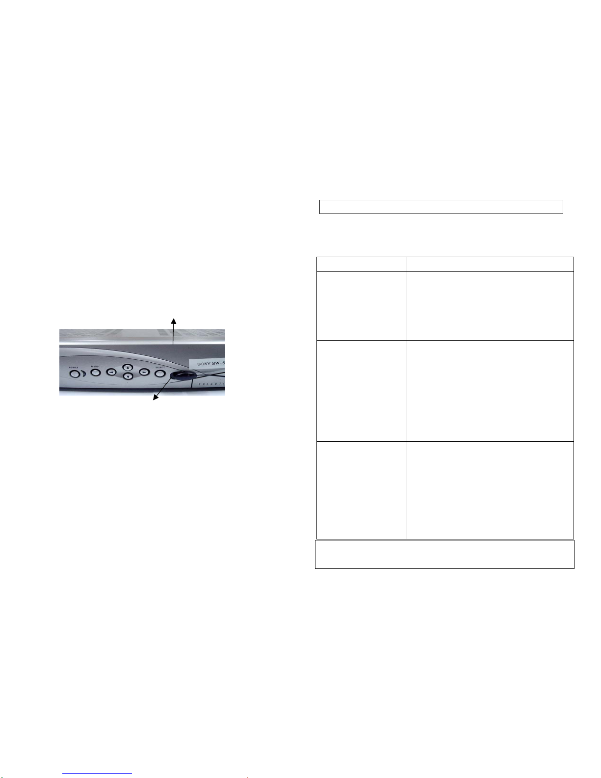
■How to Use the IR Extender Accessory
The IR extender connects to the transmitter through its own special connector
plug. The extender emits an IR signal can control your A/V equipment with
the remote signal. To use the IR extender, follow the instructions below:
(1) Plug the IR extender into the 2.5mm phone jack of transmitter’s rear
panel.
(2) Connect the infrared cable at the left of the transmitter and put one of the
LED on the infrared receiver of the A/V source. You have 3 more LED’s
at you disposal to control 3 additional A/V appliances. More the LED in
order to find the most appropriate spot.
DVD/VCR/SAT
Infrared receiver
Fig-5
(3) Position the receiver so that your remote control signal can strike the IR
window on the bottom front of the unit. To use your remote control, point
it at the front of the receiver.
-15-
G. Troubleshooting, Care and maintenance
Please read this owner's manual carefully and follow the steps described in it.
If you still have difficulties, consult the following table. It will guide you though
the most common problems and their solutions.
Note: Clean the outside plastic packaging with a soft cloth lightly moistened
with mild soap and water. Never use any abrasive scouring powder
or solvent.
-16-
Problem Possible solutions
No picture or sound •Check all cable connections.
•Make sure power plugs are pushed all the way
in.
•Check power switches on the remote TV and
Video source. (VCR, laser disc player, satellite
receiver, ect. )
•Check the power on/off switches on the
transmitter and receiver.
Interference:
Noisy picture or audio
•Adjust receiver and transmitter antenna
orientation. ( see
section on "Orienting Units for Optimum
Performance"
in this manual )
•Select a different channel by pushing the
channel
selector button on both transmitter and receiver
so that the channels match.
•If using a microwave oven, turn it off.
•Remove microwave oven from path between
transmitter and receiver.
Remote control
extender does
not work
•Check the path between the transmitter and the
audio/video source and clear any obstructions.
•Check to see if the IR window on the bottom
front of the transmitter is blocked.
•Make sure IR extender is properly rotated in the
A/V equipment you wish to control. (see section
on "Using the Remote Control Feature" in this
manual)
•Adjust remote control antennas. (see section on
"Orienting Units for Optimum Performance" in
this manual )

H. Specifications
Transmitter:
Operating Frequency Band 2.400GHz~2.4835GHz
Output Level 90 dBµV/m at 3 meters
Modulation FM (video and audio)
Channel PLL frequency synthesizer
Video Input Level 1V p-p @75 ohm
Audio Input Level 1V p-p @600 ohm (STEREO)
Input Port A/V jack-RCA line jack, SCART socket
(OPTIONAL)
Antenna Directional flat antenna
IR–remote IR output 940nm with ON/OFF keying
Power consumption 9VDC, 230mA
Dimension 120mm×88mm×34mm
Weight 180g
Receiver:
Operating Frequency Band 2.400GHz~2.4835GHz
Noise Figure 3.5dB
Channel PLL frequency synthesizer
Video Output Level 1V p-p @75 ohm
Audio Output Level 1V p-p @600 ohm (STEREO)
Output Port A/V jack-RCA line jack, SCART socket
(OPTIONAL)
Antenna Directional flat antenna
IR-remote Relay
Transmit Frequency 433.92 MHz
Infrared freq. Input 35KHz~41 KHz
Power consumption 9 VDC, 230mA
Dimension 120mm×88mm×34mm
Weight 210g
System:
Operational range up to 100 meter (line of sight)
Remote control range up to 50 meter (line of sight)
●All specification subject to change without notice
-17-
GENERAL INFORMATION:
MANUFACTURER/IMPORTER
Nedis B.V.
De Tweeling 28
5215MC ‘s-Hertogenbosch
The Netherlands
Tel.: 0031 73 5991055
Fax.: 0031 73 5999699
Email: [email protected]
WWW: www.nedis.com
-18-

ET91R-12-050
(report No.)
DECLARATION OF CONFORMITY
We, Nedis B.V.
(manufacturer’s name)
De Tweeling 28, 5215MC, ‘s-Hertogenbosch, The Netherlands
(manufacturer’s address)
Declare under our responsibility that the radio product:
KONIG VID-TRANS10SKN
(name) (type or model)
2.4Ghz Transmission / Reception System
(product description)
to which this declaration relates is in confirmity with the following standards:
Radio: EN 300 220-3 (2000-09); EN 300-440 (1999-04)
EMC: EN 301 489
Safety: EN 60065: 1998
(title, number and date of issue of the standards)
following the provisions of 1999/5/EC (R&TTE Directive).
‘s-Hertogenbosch, 13-07-2003 T. Boer
General Director
(place and date) (signature, name and function)
-19-
Table of contents


