hc-cargo SUPER 7 User manual

1Vedpak 120_Version 3_01.2018
160783
1
SUPER 7" 3+1 REAR VIEW CAMERA AND MULTIMEDIA KIT
2 USER MANUAL
Vedpak 120_Version 3_01.2018
SUPER 7” 3+1 RÜCKFAHR - KAMERA MIT MULTIMEDIA SATZ
17 BEDIENUNGSANLEITUNG
SUPER 7" 3+1 BAKKAMERA OG MULTIMEDIASÆT
28 BETJENINGSVEJLEDNING
42 MANUEL D’UTILISATION
SYSTÈME D’OBSERVATION 7” 3+1 ET KIT MULTIMEDIA
SUPER 7” 3+1 TELECAMERA PER VISIONE POSTERIORE E KIT MULTIMEDIALE
55 MANUALE D’ USO
SYSTEM OBSERWACJI PRZESTRZENI Z TYŁU POJAZDU
69 INSTRUKCJA OBSŁUGI
160783

2Vedpak 120_Version 3_01.2018
160783
CONTENT:
Features ................................................................................ 3
Installation of monitor................................................................ 3
Signal cable description .............................................................. 3
Control cable description ............................................................ 4
Front panel control ................................................................... 5
OSD menu............................................................................... 6
Display .................................................................................. 7
Installation for colour camera...................................................... 10
Vehicle installation................................................................... 11
Monitorspecications ............................................................... 12
Cameraspecications ............................................................... 13
Accessories ............................................................................ 15
PACKAGE CONTENTS:
1. 7" LED monitor 16:9.
2. Sun-hood.
3. Mounting brackets.
4. Mounting parts.
5. Control cable.
6. Camera w/ infrared LED’s and built-in microphone.
7. 20 mtr. camera cable.
8. User manual.
CAUTION:
Do not add any parts or use any accessories which are not
provided from the manufacturer.
Donotadjustsystemsettingswhendrivingtopreventtracaccidents.
Do not add pressure to the screen.
Do not sprinkle any liquid to clean the monitor. If you need to
clean it, please use a LCD cleaning cloth.

2 3 Vedpak 120_Version 3_01.2018
160783
FEATURES:
Supports up to 3 CCD Camera inputs (Mini DIN Connector).
Extra RCA input for multimedia (VCD, DVD, Game device).
Provide 1 Video / 1 Audio signal output.
Auto detection for NTSC / PAL System.
Signal Trigger for Cam A / Cam B / Cam R / AV View.
Auto brightness adjustment by CDS.
Back mirror status selection via OSD.
Video output select via OSD (Back / Door / AV).
Power latching.
Switch timer (2-100 sec.) Step selection via OSD (Cam A / Cam B / Cam R / AV View).
INSTALLATION OF MONITOR:
1. Check the package and make sure all parts are included.
2. Clip the sun-hood on to the monitor and make sure it is installed properly.
3. Install the monitor on to the bracket.
4. Adjust the monitor to an appropriate / comfortable viewing angle before tightening the screws.
5. Connect the control cable to the power socket which is located at the rear side of the monitor.
6. Monitor installation is now completed. Each control cable wire is attached with a sticker to indicate its signal
function.
SIGNAL CABLE DESCRIPTION:
1. CAM A (Mini din)
Fixed for Direction Light (Left Turn Light) vision camera
2. CAM B (Mini din)
Fixed for Direction Light (Right Turn Light) vision camera
3. CAM R (Mini din)
Fixed for rear vision camera
4. LIVE VIDEO OUT (RCA - White wire).
On screen audio loop out (for recording, second monitor or other device).
5. LIVE AUDIO OUT (RCA - Black wire).
On screen audio loop out (for recording, second monitor or other device).
6. AV VIDEO IN (RCA - Yellow wire).
Connection for any Video signal (such as DVD, VCD, Game)
7. AV AUDIO IN (RCA - Red wire).
Connection for any Audio signal (such as DVD, VCD, Game)

4Vedpak 120_Version 3_01.2018
160783
CONTROL CABLE DESCRIPTION:
Cableconguration
Don’t connect the red wire (power
wire) of this product directly to the
battery. Connect the red wire of this
product to the ACC of the ignition
key switch. Failure to do so may
result in permanent damage of the
product.
WIRE COLOUR
Red
Black
White
Yellow
Orange
Blue
FUNCTION
Acc power
(DC 9.6-DC 32 V)
GND
Parking Control
Cam A
Cam B
Reverse Control
Cam R
REMARKS
Active GND
Allows AV or extra camera
Active Power Level.
Connect to Direction
Light (Left turn Light)
Active Power Level.
Connect to Direction
Light (Right Turn Light)
Active Power Level
Connect to Reverse
ON SCREEN VIEW

4 5 Vedpak 120_Version 3_01.2018
160783
FRONT PANEL CONTROL:
POWER: Press the POWER button to activate the monitor or to keep the monitor under stand by mode.
SOURCE: Press this button to select image between
CAM A CAM B CAM R CAM A……..
With activated hand break, press this button to select image sequence
AV CAM A CAM B CAM R AV………..
JUMP: Press this button, it can switch CAM A, CAM B, CAM R recurrently.
With activated hand break and check the Jump AV option is ON, press
this button to select image sequence
AV CAM A CAM B CAM R AV………..
MENU: This encoder switch provides the following function:
1. Activate OSD menu.
Press the switch to activate the OSD menu.
2. Enter-function:
Press the encode switch to act as "Enter": Functions under the OSD menu.
3. Volume value:
Exit the OSD menu: user can turn this switch left or right to adjust the volume value.
6Vedpak 120_Version 3_01.2018
160783
OSD MENU:
1. Press the MENU button to enter the OSD Menu.
2. Turn the MENU button left or right to select the setting you wish to proceed.
The colour of the content will turn yellow to identify your selection.
3. Press the MENU button again until the colour of the value turns yellow.
Turn the MENU button left or right to adjust your setting value.
4. Press menu button again to return to OSD MENU.
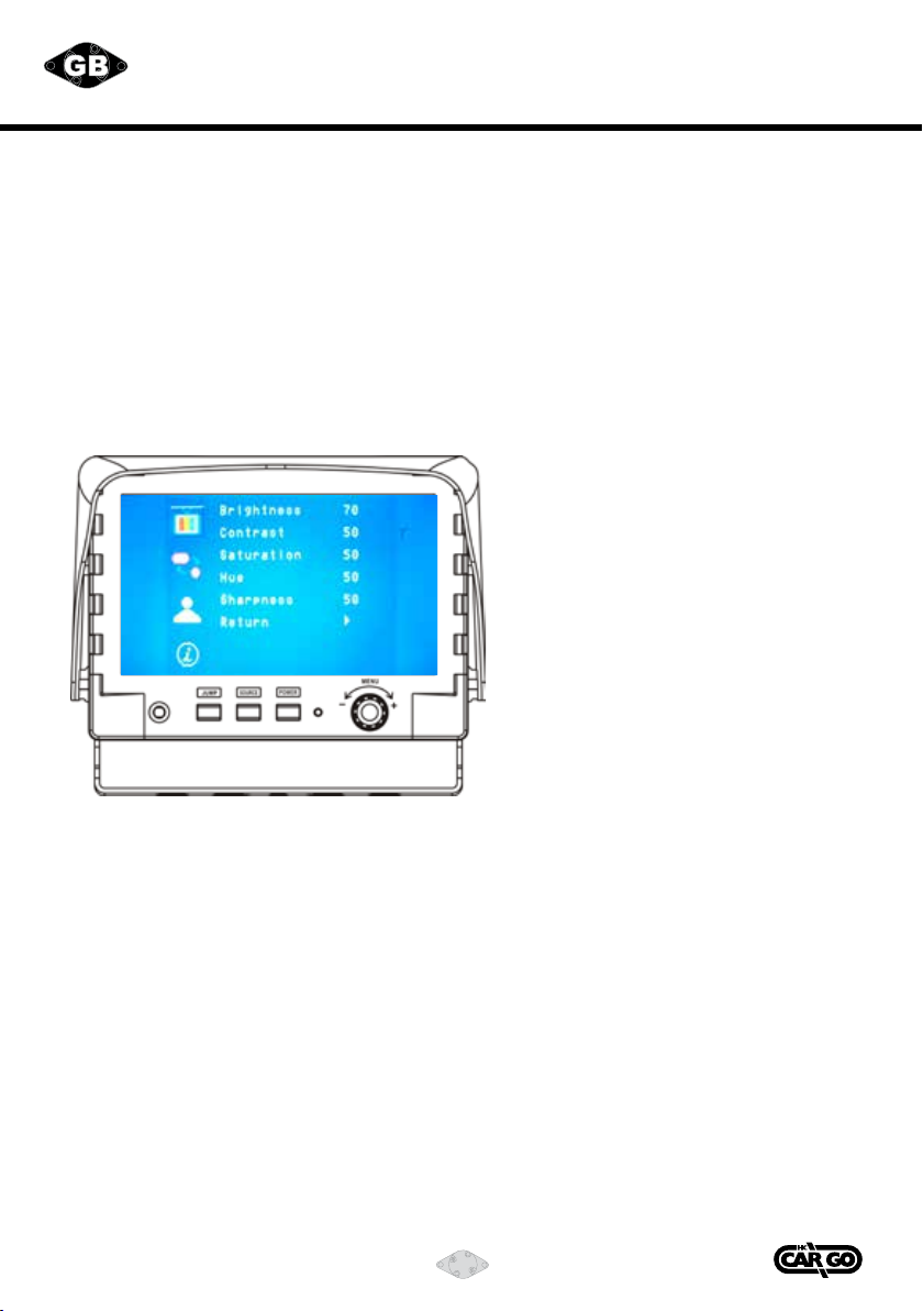
Enter to main menu:
6 7 Vedpak 120_Version 3_01.2018
160783
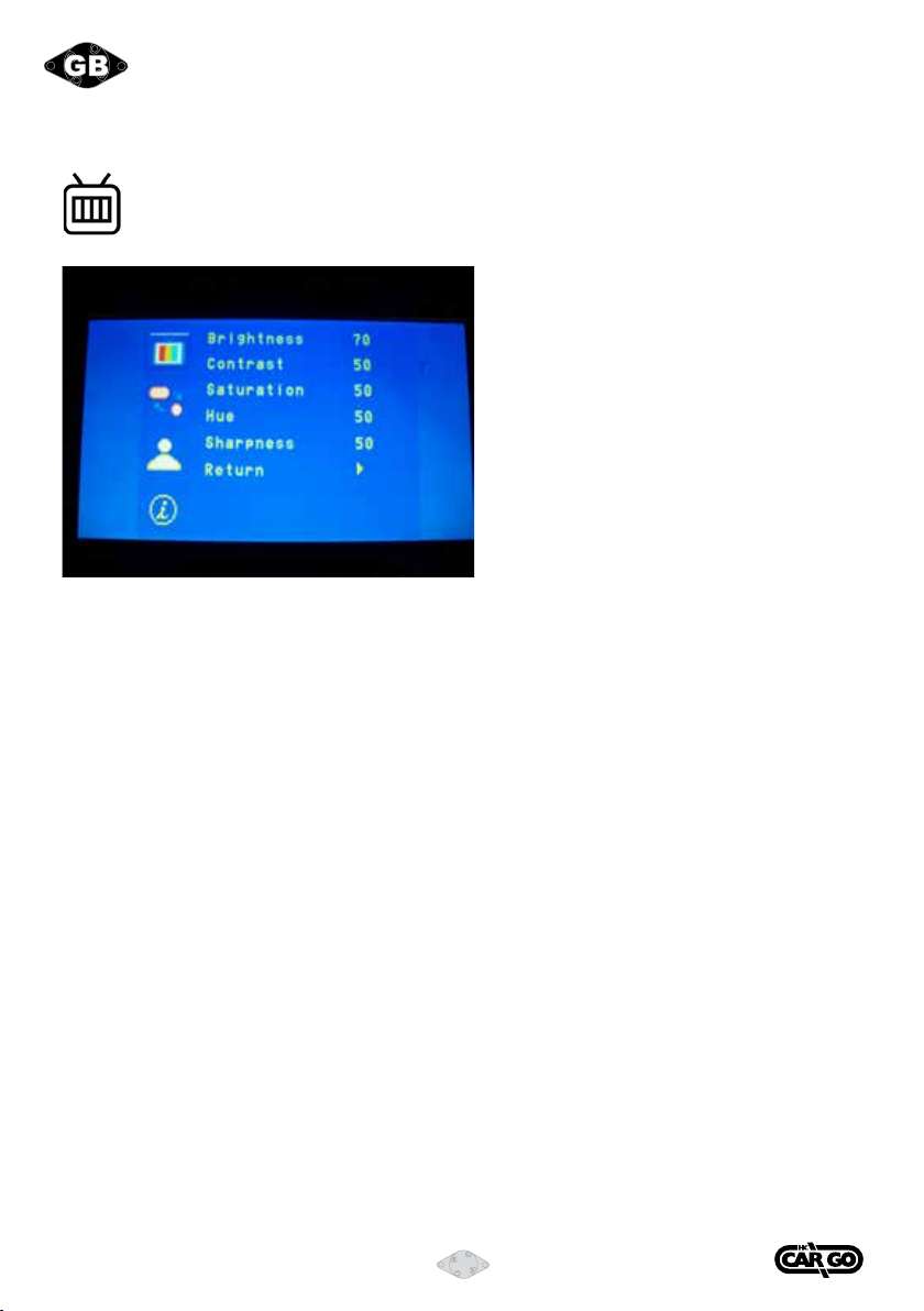
SCREEN MENU:
ThismenusetupcontainsdierentsettingfortheTFTLCD.
Brightness:
Provide adjustment for the overall picture shade and brightness of the TFT display.
Setting value from 0 ~ 100. Default value 70.
Contrast:
Provide adjustment for the contrast level of the TFT display between the light and dark area.
Setting value from 0 ~ 100. Default value 50.
Saturation:
Provide adjustment for the colour of the TFT display between the light and dark area.
Setting value from 0 ~ 100. Default value 50.
Hue:
Provide adjustment for the picture TINT between light and dark area.
Setting value from 0 ~ 100. Default value 50. (Only in NTSC system available).
Sharpness:
Provide adjustment for the edge contrast (acutance) level of TFT display.
Setting value from 0 ~ 100. Default value is 50.
Return:
Return to OSD menu selection screen.

8Vedpak 120_Version 3_01.2018
160783
DISPLAY Menu
Thismenusetupcontainstheonscreenidentication
and the activation of the distance gauge.
Cam Name
Select “ON” to show the source of video input title on screen or “OFF” to keep it invisible.
Default value is ON.
Distance Gauge
Set the distance gauge “ON” to show the distance gauge on screen while reversing
or “OFF” to deactivate. Default value is ON.
(This “DISTANCE GAUGE” is for user’s reference only)
Auto Day&Night
Select “ON” to activate the auto day & night function or “OFF” to
deactivate it. Default value is OFF.
OSD Lock
This function provides protection when an unauthorized person tries to access the OSD settings.
Press JUMP and Source key simultaneously for over 5 seconds to unlock. Default value is OFF.
Users must turn on LCD in order to run unlock process. All function buttons are still
working during OSD Menu lock up period.
Return
Return to OSD menu selection screen.

8 9 Vedpak 120_Version 3_01.2018
160783
CAMERA Menu
This menu set up contains the Camera and Jump setting.
CAM A MIRROR
Select “ON” to activate the mirror function for CAM A “OFF” for a normal image.
Default value is OFF.
CAM B MIRROR
Select “ON” to activate the mirror function for CAM B or “OFF” for a normal image.
Default value is OFF.
CAM R MIRROR
Select “ON” to activate the mirror function for CAM R or “OFF” for a normal image.
Default value is ON.
Jump Dwell
Setting Jump dwell value from 2~100.
Default value is “3”.
Jump AV
Jump function included AV channel or not. If setting is ON but system does not work, you should
check the PARK trigger status. Default value is “ON”.
RECALL
Recall factory default.
Return
Return to OSD menu selection screen.
Information
This menu set up contains the Exit
functionandshowsthermwareversion.

10 Vedpak 120_Version 3_01.2018
160783
INSTALLATION FOR COLOUR CAMERA
INSTALLATION
With standard mounting bracket and fasteners included in the package, the camera can be mounted rmly
at the required position of the vehicle.
1. Install the camera on the mounted camera bracket using proper fasteners (included in the package).
Decide direction for the camera to view when installing the camera on the bracket.
2. Run the built-in camera cable connection (1.5 mtr.) to monitor with camera extension cable
(20 mtr. standard length included in the package) into the vehicle body (make a 13 mm. (½") hole on
thevehiclebodyifnecessary).Connectthecableconnectorsrmlyinsidethevehiclewithaidofa
cable-tie, and use weather sealer strip to help protect the cable connection.
Seal the hole properly with weather sealant where the cable runs through vehicle body
3. For maximum weather protection, the cable connection is always recommended NOT to be left
outside the vehicle.
4. This device has the function of night viewing. In the dark, the IR will be enabled and the image is more clearly.
CONNECTION OF CAMERA 4
Connection of camera 4 is done using the adapter Cargo 160603.
Yellow RCA jack to VIDEO IN.
White RCA jack to AUDIO IN.
Furthermore 12 V / GND is connected to the camera via the red and black leads of the adapter.
CAUTION
1. Adjust the camera angle so that the rear bumper or the rear end of the vehicle is visible on the
monitor (at the bottom brim of the view).
2. To prevent vibration, be sure to install the camera in a position at which it can be installed securely.
Take the necessary measures for reinforcement if there is no place the camera can be installed securely.
3. Note that there will be blind spots if the camera is installed on the rear bumper, step, or in other low
position.
Avoid installing the camera in places where the lens can be easily get dirty from mud, exhaust gases, etc.
4. Be sure to waterproof the holes used to install the camera mounting bracket on the car,
the bolts, and the cable holes.

10 11 Vedpak 120_Version 3_01.2018
160783
VEHICLE INSTALLATION:
1. Install camera R (for rear view).
2. Use a measuring tool to mark out the distance behind the vehicle.
3. Adjust the viewing angle of the camera so that the distance gauge shown from the TFT
match to the distance behind the vehicle.
Switch to Rear view with source button, the screen always display on 16:9
While rear viewing, the screen always display on 4:3 to correct size percentage
SOURCE button: Rear viewing:
9
4
3
16

12 Vedpak 120_Version 3_01.2018
160783
MONITOR SPECIFICATIONS:
Screen size 7" (Diagonal) 16:9.
Active area 154.08 x 86.58 mm.
Pixelconguration 0.107x0.370.
Resolution 2400 x 480.
Viewing angle 60°.
Power source DC 9.6 V. ~ DC 32 V.
Contrast ratio 500:1.*
Brightness 400 cd/cm².*
Input Interface
Composite connector RCA.
Input signal 1 Vpp.
Impedance 75 Ω.
Camera
Connector 6 pin mini din.
Input video signal level 1 Vpp.
Impedance 75 Ω.
Input audio signal level 1 Vpp.
Power output DC 12 V. 350 mAmp.
AV Audio In
Connector RCA.
Input signal level 1Vpp.
Impedance 75 Ω.
Output Interface
Composite Life video out.
Connector RCA.
Input signal level 1Vpp.
Composite Video Cam out.
Connector RCA.
Input signal level 1Vpp.
Impedance 75 Ω.
Audio Live Out
Connector RCA.
Input signal level 1Vpp.
Impedance 1 KΩ.
Weight Nt. 1.79 kg. Br. 2.2 kg.
Dimension L: 191 mm. H: 140 mm. D: 51 mm.
Environmental
Operation temp. -10C°~70C°.
Storage temperatur -30C°~80C°.
Humidity 20%~80%.
*Thebrightnessandcontrastratioarefrompanelspecication.
DesignandspecicationaresubjecttochangewithoutnoticeVH1.0.

12 13 Vedpak 120_Version 3_01.2018
160783
Camera Harness:
Pin No.
1
2
3
4
5
6
7
Part description
GND
Video output
Power DC 12
Audio output
Normal / mirror
GND
GND
14 15 Vedpak 120DE_Version 2_160909
160783
D
Kamera Steckerbelegung: Stecker-Nr.
1
2
3
4
5
6
7
Bezeichnung
GND
Videoausgang
Spannung 12V Gleichstrom
Audioausgang
Normal / Spiegelansicht
GND
GND
Kamera Spiegel (M) / Normal (N) Einstellung
Für Spiegelfunktion -
Pfeil drehen auf M.
Für normale Funktion -
Pfeil drehen auf N.
Camera Mirror (M) / Normal (N) adjustment
For mirror function -
Turn arrow to M.
For normal function -
Turn arrow to N.

14 Vedpak 120_Version 3_01.2018
160783
CAMERA SPECIFICATIONS
Pick-up Device 1/3" image sensor interline transfer CCD
Image Size 4.82 x 3.64 mm.
Elements NTSC / EIA: 510 (H) x 492(V)
PAL / CCIR: 500 (H) x 582(V)
Horizontal Resolution More than 380 TV lines
Shutter Control NTSC 1/60-1/100.000 sec.
PAL 1/50-1/100.000 sec.
Scanning System 2:1 Interlace
Synchronization Internal
S/N Ratio More than 48dB (AGC OFF)
Gain Control AUTO
Sensitivity 0.5 lux / F2.0
Video Output Composite 1.0 Vp-p / 75 ohm
Power Consumption 2 W. (max.)
Dimensions 62 mm.(D) x 104.6 mm.(W) x 62 mm.(H)
Weight (per unit) 650 g.
Synchro NTSC / EIA: H: 15.750 KHZ V: 60 Hz
PAL / CCIR: H: 15.625 KHZ V: 50 Hz
DC Power Source DC 12 V.
Board Lens Mount 2.5 mm. / F 2.0
IR IR LED 850 nm Auto Control by CDS
Operation Temperature -20 to 50° C.
Storage Temperature -20 to 70° C.

14 15 Vedpak 120_Version 3_01.2018
160783
ACCESSORIES:
160796
Camera w/ infrared LED’s for night vision.
Wide view angle, 112° horizontal, 91° vertical, 156° diagonal.
170942
Magnet w/ metalbase for cameras.
160663
Trailer cable Kit. W/ 3.5 mtr. coiled cable.
Switch w/ location and function light. ON/OFF.
180206 12 V.
180207 24 V.
160610
Camera, O.D. 30 mm. L. 70 mm.
Wide view angle, 130° diagonal.
160790
Camera, O.D. 21 mm. L. 40 mm.
Wide view angle, 170° diagonal.
Extension cables.
160672 6 mtr.
160613 10 mtr.
160612 15 mtr.
160611 20 mtr.
160603
Connection cable from 6 PIN MINI DIN to RCA.
Symbolplates for Cargo 180206 and 180207.
181462 Green.
181463 Red.
181464 Camera.

16 Vedpak 120_Version 3_01.2018
160783
INHALT:
Besonderheiten ....................................................................... 17
Einbau des Monitors.................................................................. 17
Signalkabelbeschreibung ............................................................ 17
Kontrollkabelbeschreibung.......................................................... 18
Schalter und Bedienung………………………………... .................................. 19
OSD-Menü – Anzeige.................................................................. 20
Screen menu .......................................................................... 21
Display menu.......................................................................... 22
Camera menu ......................................................................... 23
Installation der Farb-Kamera....................................................... 24
Fahrzeugeinbau....................................................................... 25
Monitoreigenschaften................................................................ 26
Kameraeigenschaften................................................................ 28
Zubehör ................................................................................ 29
PACKUNGSINHALT:
1. 7" LED Monitor 16:9
2. Sonnenblende
3. Einbauhalterungen
4. Einbauzubehör
5. Steuerungskabel
6. Kamera mit Infrarot LED´s und eingebautem Mikrofon.
7. 20 mtr. Kamerakabel
8. Bedienungsleitung
ACHTUNG:
Fügen Sie keine Teile hinzu oder verwenden Sie irgendwelches Zubehör,
das vom Hersteller nicht im Lieferangebot steht.
Fahren Sie nie weiter, als es Ihnen die Systemanzeige vorgibt,
um Verkehrsunfälle zu vermeiden.
Üben Sie nie Druck auf den Bildschirm aus.
SprühenSienieirgendwelcheüssigeReinigungsmittelaufden
Bildschirm. Benutzen Sie zur Reinigung nur ein LCD-Reinigungstuch.

16 17
Vedpak 120_Version 3_01.2018
160783
BESONDERHEITEN:
Unterstützt bis zu 3 CCD Kamerasignale (Mini-DIN-Stecker)
Extra RCA-Eingang für Multimedia (VCD, DVD, Spielekonsole).
Stellt 1Video / 1Audio Signalausgang zur Verfügung
Automatische Erkennung für NTSC / PAL-System
Signalschalter für Bild von CAM A / CAM B / CAM R / AV
Automatische Tag/Nacht Kontrolle mit CDS
Rückseitiger Spiegelstatusvorwähler über OSD
Video Ausgangswähler über OSD (Hinten / Tür / AV)
Leistungskontrolle
Zeitschalter (2-100 Sekunden) Schrittauswahl über OSD (CAM-A / B CAM / CAM-R / AV)
INSTALLATION DES MONITORS:
1. Überprüfen sie den Packungsinhalt und stellen Sie sicher, das alle Teile enthalten sind.
2. Klipsen Sie die Sonnenblende auf den Monitor und stellen Sie sicher, das sie ordnungsgemäß befestigt ist.
3. Installieren Sie den Monitor auf die Halterung.
4. Richten Sie den Monitor vor dem festziehen der Schrauben in einen passenden und bequemen
Betrachtungswinkel aus.
5. Schließen Sie das beigelegte Anschlusskabel an der Rückseite des Monitors an.
6. Die Monitorinstallation ist jetzt abgeschlossen. Die Steuerleitungen sind mit einem Aufkleber markiert,
um die Signalfunktionen anzuzeigen.
SIGNALKABELBESCHREIBUNG:
4Vedpak 120DE_Version 2_160909
160783
D
5
Besonderheiten:
Unterstützt bis zu 3 CCD Kamerasignale (Mini-DIN-Stecker)
Extra RCA-Eingang für Multimedia (VCD, DVD, Spielekonsole).
Stellt 1Video / 1Audio Signalausgang zur Verfügung
Automatische Erkennung für NTSC / PAL-System
Signalschalter für Bild von CAM A / CAM B / CAM R / AV
Automatische Tag/Nacht Kontrolle mit CDS
Rückseitiger Spiegelstatusvorwähler über OSD
Video Ausgangswähler über OSD (Hinten / Tür / AV)
Leistungskontrolle
Zeitschalter (2-100 Sekunden) Schrittauswahl über OSD (CAM-A / B CAM / CAM-R / AV)
installation des Monitors:
1. Überprüfen sie den Packungsinhalt und stellen Sie sicher, das alle Teile enthalten sind.
2. Klipsen Sie die Sonnenblende auf den Monitor und stellen Sie sicher, das sie ordnungsgemäß befestigt ist.
3. Installieren Sie den Monitor auf die Halterung.
4. Richten Sie den Monitor vor dem festziehen der Schrauben in einen passenden und bequemen
Betrachtungswinkel aus.
5. Schließen Sie das beigelegte Anschlusskabel an der Rückseite des Monitors an.
6. Die Monitorinstallation ist jetzt abgeschlossen. Die Steuerleitungen sind mit einem Aufkleber markiert,
um die Signalfunktionen anzuzeigen.
signalkaBelBeschreiBung:
1. CAM A (Mini DIN)
Fixiert für Kamerasicht nach links (linker Fahrtrichtungsanzeiger)
2. CAM B (Mini DIN)
Fixiert für Kamerasicht nach rechts (rechter Fahrtrichtungsanzeiger)
3. CAM R (Mini DIN)
Fixiert für Rücksichtkamera
4. LIVE VIDEO AUS (RCA – Weißes Kabel)
Videoschleife auf dem Bildschirm (zum Aufzeichnen, zweiten Monitor oder andere Geräte)
5. LIVE AUDIO AUS (RCA – Schwarz Kabel)
Audioschleife auf dem Bildschirm (zum Aufzeichnen, zweiten Monitor oder andere Geräte)
6. AV VIDEO EIN (RCA – Gelbes Kabel)
Verbindung für beliebiges Videosignal (wie DVD, VCD, Spielkonsole)
6. AV AUDIO EIN (RCA – Rotes Kabel)
Verbindung für beliebiges Audiosignal (wie DVD, VCD, Spielkonsole)

18 Vedpak 120_Version 3_01.2018
160783
KONTROLLKABELBESCHREIBUNG:
Kabelkonguration
Schließen Sie das rote Kabel
(Spannungsversorgung) der
Kontrolleinheit nicht direkt
an die Fahrzeugbatterie an.
Schließen Sie das rote Kabel an die
Radiostellung des Zündstartschalters
an. Nichtbeachtung kann einen
dauerhaften Schaden des Produktes
hervorrufen.
WIRE COLOUR
ROT
SCHWARZ
WEISS
GELB
ORANGE
BLAU
FUNCTION
ACC Strom
MASSE
Einparken
Links abbiegen
Rechts abbiegen
Rückwärts
REMARKS
Masse aktiv
Aktiver Anschluss
für Ansteuerung
Kamera links (Linker
Fahrtrichtungsanzeiger)
Aktiver Anschluss für
AnsteuerungKamera
rechts (Rechter
Fahrtrichtungsanzeiger)
Aktiver Anschluss an
Rückfahrscheinwerfer
ON SCREEN VIEW
18 19 Vedpak 120_Version 3_01.2018
160783
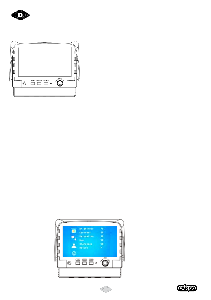
BILDSCHIRMBEDIENUNG:
POWER: POWER Schalter zum aktivieren des Monitors oder um
in Stand-By Modus zu schalten.
SOURCE: Auswahlschalter zum Auswählen der Bildsequenz
CAM-A / CAM-B / CAM R / CAM A.............
Bei gezogener Handbremse, press this button to
select image sequence
AV CAM A CAM B CAM R AV………..
JUMP: Dieser Knopf schaltet nacheinander CAM A, CAM B und CAM R ein.
Bei gezogener Handbremse und nach Kontrolle, dass die Jump-AV-Option AN ist,
diesen Knopf zur Wahl der Bildsequenz drücken.
AV CAM A CAM B CAM R AV………..
MENU: Der MENÜ Schalter unterstützt folgende Funktionen:
1. Aktivieren des OSD-Menüs. Drücken Sie den Drehschalter zum aktivieren des OSD-Menüs.
Nachdem das OSD-Menü aktiviert ist, wird im Falle, dass der Benutzer im Menü nicht
weitergeht, das OSD-Menü innerhalb von ein paar Sekunden automatisch abgeschaltet.
2. Eingabefunktion: Benutzen Sie die Menü-Taste als „Enter“ Taste zur Funktionsauslösung im
OSD-Menü.
3. Lautstärkeregelung: Verlassen Sie das OSD-Menü. Um die Lautstärke einzustellen, drehen
Sie links oder rechts am Menü-Drehschalter.
OSD MENU:
1. Drücken Sie den MENÜ-Schalter um das OSD Menü aufzurufen.
2. Drehen Sie den MENÜ-Schalter links oder rechts um die Einstellungen auszuwählen die Sie benötigen.
UmdasIdentiziereneinfacherzugestalten,wirdderjeweiligeMenü-Punktmiteinemgelben
Streifen hinterlegt.
3. Den Knopf MENU wieder drücken, bis die Farbe des Wertes auf gelb wechselt.
Den Knopf MENU nach links oder rechts drehen, um den eingestellten Wert zu ändern.
4. Den Knopf MENU wieder drücken, um zum OSD MENÜ zurückzukehren.
Eingabe zum Hauptmenü:
20 Vedpak 120_Version 3_01.2018
160783
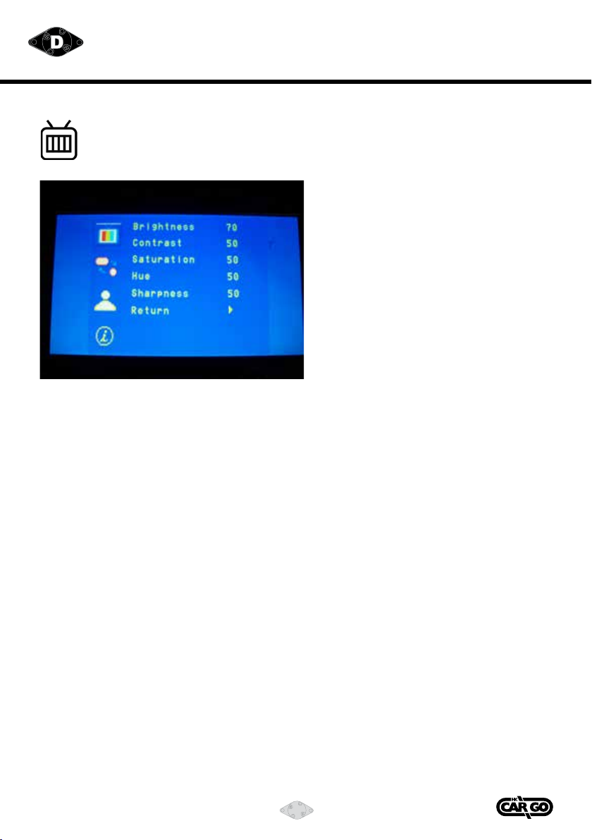
SCREEN MENU:
Dieses Menü enthält verscheidene Einstellungsmöglichkeiten für
das TFT LCD.
Brightness:
Mit dieser Einstellung passen Sie für die gesamte TFT-Anzeige den Helligkeitsbereich an.
Der voreingestellte Wert ist 70. Der einstellbare Wert geht von 0-100.
Contrast:
Mit dieser Einstellung passen Sie das Kontrastniveau der TFT-Anzeige zwischen dem hellen und dem
dunklen Bereich an. Der voreingestellte Wert ist 50. Der einstellbare Wert geht von 0-100.
Saturation (Farbe):
Mit dieser Einstellung passen Sie das Farbniveau der TFT-Anzeige zwischen dem hellen und dem
dunklen Bereich an. Der voreingestellte Wert ist 50. Der einstellbare Wert geht von 0-100.
Hue:
Mit dieser Einstellung passen Sie die Farbtonabweichung der TFT-Anzeige zwischen dem hellen und dem dunklen
Bereich an. Der voreingestellte Wert ist 50. Der einstellbare Wert geht von 0-100.
(Nur bei NTSC-System verfügbar.)
Sharpness:
Ermöglicht Anpassung des Kantenkontrasts (Kantenschärfe) des TFT-Displays.
Setting value from 0 ~ 100. Default value is 50.
Return:
Zurück zur vorhergehenden Seite.
Table of contents
Languages:


