Kontron JFLEX-DUALDVI User manual

JFLEX-DUALDVIUser’s Guide
Document Revision 0.1
PRELIMINARY


Kontron
JFLEX-DUALDVI User’s Guide
1
CONTENTS
1. USERINFORMATION...........................................................................................2
1.1 About This Manual........................................................................................2
1.2 Copyright Notice..........................................................................................2
1.3 Trademarks ................................................................................................2
1.4 Standards..................................................................................................3
1.5 Warranty ...................................................................................................3
1.6 Technical Support ........................................................................................4
2. INTRODUCTIONS...............................................................................................5
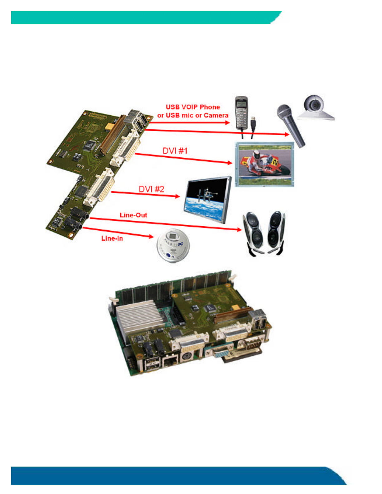
2.1 JFLEX-DUALDVI...........................................................................................5
3. SPECIFICATION.................................................................................................7
3.1 JFLEX-DUALDVI with Silicon Image SIL164 and Texas Instruments TFP410.....................7
3.2 Mechanical Specifications ..............................................................................7
3.2.1. Dimensions...........................................................................................7
3.3 Electrical Specifications.................................................................................8
3.3.1. Supply Voltage ......................................................................................8
3.3.2. Supply Voltage Ripple..............................................................................8
3.3.3. Supply Current.......................................................................................9
3.4 Environmental Specifications..........................................................................9
3.4.1. Temperature.........................................................................................9
3.4.2. Humidity..............................................................................................9
4. MODULEFUNCTIONS........................................................................................10
4.1 AC ’97 Sound Controller............................................................................... 10
Line-In Connector X2........................................................................................ 10
Line-Out Connector X1 ...................................................................................... 10
CD-ROM Input X8 ............................................................................................. 11
4.2 DVI (Digital Video Interface)......................................................................... 11
4.3 DVI Connector X3 Pinout on JFLEX-DUALDVI...................................................... 12
4.4 DVI Connector X4 Pinout on JFLEX-DUALDVI...................................................... 13
5. APPENDIXA:BLOCKDIAGRAM............................................................................14
6. APPENDIXB:CONNECTORLAYOUT.......................................................................15
6.1 Connector Locations................................................................................... 15
7. APPENDIXC:LITERATUREANDSTANDARDS ...........................................................16
7.1 Buses and General PC Architetcure.................................................................. 16
7.1.1. USB.................................................................................................. 16
7.1.2. AC ’97 ............................................................................................... 16
APPENDIX D: DOCUMENT-REVISIONHISTORY...............................................................17

Kontron
2JFLEX-DUALDVI User’s Guide
1. USER INFORMATION
1.1 About This Manual
This document provides information about products from Kontron Embedded Computers AG
and/or its subsidiaries. No warranty of suitability, purpose, or fitness is implied. While
every attempt has been made to ensure that the information in this document is accurate,
the information contained within is supplied “as-is” and is subject to change without
notice.
For the circuits, descriptions and tables indicated, Kontron assumes no responsibility as far
as patents or other rights of third parties are concerned.
1.2 Copyright Notice
Copyright © 2005 Kontron Embedded Computers AG.
All rights reserved. No part of this manual may be reproduced, transmitted, transcribed,
stored in a retrieval system, or translated into any language or computer language, in any
form or by any means (electronic, mechanical, photocopying, recording, or otherwise),
without the express written permission of Kontron.
JUMPtec Industrielle Computertechnik AG and Kontron Embedded Computers AG merged in
July 2002. JUMPtec is now known as Kontron Embedded Modules GmbH. Products labeled
and sold under the Kontron Embedded Modules name (formerly JUMPtec) are now
considered Kontron products for all practical purposes, including warranty and support.
DIMM-PC®, PISA®, ETX Components SBC, JUMPtec®, and Kontron Embedded Modules are
registered trademarks of Kontron Embedded Modules GmbH©.
1.3 Trademarks
The following lists the trademarks of components used in this board.
†IBM,XT,AT,PS/2andPersonalSystem/2 aretrademarksofInternationalBusiness
MachinesCorp.
†MicrosoftisaregisteredtrademarkofMicrosoftCorp.
†IntelisaregisteredtrademarkofIntelCorp.
†Allotherproductsandtrademarksmentionedinthismanualaretrademarksoftheir
respectiveowners.

Kontron
JFLEX-DUALDVI User’s Guide
3
1.4 Standards
Kontron Embedded Modules is certified to ISO 9000 standards.
1.5 Warranty
This Kontron Embedded Modules product is warranted against defects in material and
workmanship for the warranty period from the date of shipment. During the warranty
period, Kontron Embedded Modules will at its discretion decide to repair or replace
defective products.
Within the warranty period, the repair of products is free of charge as long as warranty
conditions are observed.
The warranty does not apply to defects resulting from improper or inadequate maintenance
or handling by the buyer, unauthorized modification or misuse, operation outside of the
product’s environmental specifications or improper installation or maintenance.
Kontron Embedded Modules will not be responsible for any defects or damages to other
products not supplied by Kontron Embedded Modules that are caused by a faulty Kontron
Embedded Modules product.

Kontron
4JFLEX-DUALDVI User’s Guide
1.6 Technical Support
Technicians and engineers from Kontron Embedded Modules and/or its subsidiaries are
available for technical support. We are committed to making our product easy to use and
will help you use our products in your systems.
Before contacting Kontron Embedded Modules technical support, please consult our Web
site at http://www.kontron-em.com/index-en.html for the latest product documentation,
utilities, and drivers. If the information does not help solve the problem, contact us by
telephone.
Kontron EUROPE
Kontron Embedded Modules
Brunnwiesenstr. 16
94469 Deggendorf –Germany
Tel: +49 (0) 991-37024-0
Fax: +49 (0) 991-37024-109
Kontron AMERICA
14118 Stowe Dr
Poway, CA 92064-7147
Tel: (888)-294-4558
Fax: (858) 677-0898
Customer Service/Technical
Support:
(800) 480-0044 (US Only)
Email:
Website:
www.kontron.com
Kontron ASIA
HeiHu Office HanKang Office
4F, No. 415 Far East Science Park
Ti-Ding Blvd. Sec. 2 2nd Floor No. 2, Lane 50,
NeiHu District Nan Kang Road Section 3,
Nan Kang District
Taipei 114, Taiwan Taipei 115, Taiwan
Tel: +886-2-2799-2789 Tel: +886-2-2782-0201
Fax: +886-2-2799-7399 Fax: +886-2-2782-7486
Email: sales-asia@kontron.com.tw
Website: www.kontron.com.tw

Kontron
JFLEX-DUALDVI User’s Guide
5
2. INTRODUCTIONS
2.1 JFLEX-DUALDVI
The JFLEX-DUALDVIis an extension for Kontrons JRex 3,5’’ SBC family.
Following features are provided by theJFLEX-DUALDVI:
•One Realtek ALC650 sound controller compatible to IntelAudio Codec
´97 Rev. 2.2
Input connectors: Line, CD-ROM (internal)
Output connectors: Line
•DVI digital
•USB connector
TheJFLEX-DUALDVIissupportedbythefollowingBoard:
JRex–PM,a3.5”sizedSingleBoard ComputerwithIntelPentiumMprocessors.
http://emea.kontron.com/index.php?id=226&cat=58&productid=241

Kontron
6JFLEX-DUALDVI User’s Guide
The assembled JRex-PM and JFLEX-DUALDVI module looks like this and allows these connections:

Kontron
JFLEX-DUALDVI User’s Guide
7
3. SPECIFICATION
3.1 JFLEX-DUALDVIwith Silicon Image SIL164 and Texas
Instruments TFP410
-TheJFLEX-DUALDVIsupportsDVIresolutions from VGA toSXGA@60Hz
-ProgrammablebyUsingtheI2CSerialInterface
-ToactivatetheJFLEX-DUALDVIplease enable in the Phoenix Bios Setup:
->Advanced ->Display Control: EFP Only or CRT+EFP
3.2 Mechanical Specifications
3.2.1. Dimensions
†82.5mmx140.7mm
†Height(total)approx.15mm

Kontron
8JFLEX-DUALDVI User’s Guide
140,6
15,00
5,00 10,00
3.3 Electrical Specifications
3.3.1. Supply Voltage
†5VDC+/-5%
†3,3VDC+/-5%
3.3.2. SupplyVoltageRipple
†Maximum100mVpeaktopeak0–20MHz

Kontron
JFLEX-DUALDVI User’s Guide
9
3.3.3. Supply Current
Power-consumption tests were executed during different applications conducted.
3.4 Environmental Specifications
3.4.1. Temperature
†Operating:
•Ambient temperature: 0 to +60°C
†Non-operating:-10to+85°C
3.4.2. Humidity
†Operating:10%to90%(noncondensing)
†Nonoperating:5%to95%(noncondensing)

Kontron
10 JFLEX-DUALDVI User’s Guide
4. MODULE FUNCTIONS
4.1 AC ’97 Sound Controller
The JFLEX-DualDVI uses a Realtek ALC650 sound codec. The ALC650 is an
18-bit, full duplex AC’97 2.2 compatible stereo audio CODEC designed for PC
multimedia systems, including host/soft audio and AMR/CNR based designs. The
ALC650 incorporates proprietary converter technology to achieve a high SNR,
greater than 90 dB.
The ALC650 also supports an AC’97 2.2 compliant S/PDIF out function which
allows easy connection from the PC to consumer electronic products, such as
AC3 decoder/speaker and mini disk.
All major operating systems support the interface.
The ALC650 provides:
•High performance CODEC with high S/N ratio (>90 dB)
•18-bit ADC and 20-bit DAC resolution
•Compliant with AC’97 2.2 specifications
•18-bit stereo full-duplex CODEC with independent and variable sampling rate
•1 analog line-level stereo input with 5-bit volume control: LINE_IN, (CD_IN is
possible)
•Power management capabilities
Line-In Connector X2
Line-Out Connector X1
Pin Signalname
1GND
2L_IN Left
3L_IN Right
Pin Signalname
1GND
2L_OUT Left
3L_OUT Right

Kontron
JFLEX-DUALDVI User’s Guide
11
CD-ROMInputX8
Pin 1
4.2 DVI (Digital Video Interface)
The JFLEX-DualDVIis equipped with a standard Digital Video Interface. DVI has
the potential to unify the digital display industry. The DVI 1.0 specification was
endorsed in April 1999 by the Digital Display Working Group (DDWG), an
industry organization established by Intel. Membership consists of major PC and
display manufacturers. TI is a DDWG participant.
DVI is based on Transition-Minimized Differential Signaling (T.M.D.S.), a
technology that offers advantages in video data transmission. DVI adds a specific
hardware interface that is compatible with older T.M.D.S.-based interfaces such
as the Plug & Display (P&D) and Digital Flat Panel (DFP) standards endorsed by
the Video Electronics Standards Association(VESA). DVI technology is non-
proprietary to encourage the most widespread adoption.
Pin
Signalname
Function
1CD_IN Right Audio Input Right Channel
2NC
3CD_IN Left Audio Input Left Channel
4GND Signal Ground

Kontron
12 JFLEX-DUALDVI User’s Guide
4.3 DVI Connector X3Pinout on JFLEX-DUALDVI
Pin Name Pin Name
1TMDS Data2-13 Not connected
2TMDS Data2+ 14 +5 V Power
3GND 15 GND
4Not connected 16 Hot Plug Detect
5Not connected 17 TMDS Data0-
6DDC Clock [SCL] 18 TMDSData0+
7DDC Data [SDA] 19 GND
8Not connected 20 Not connected
9TMDS Data1-21 Not connected
10 TMDS Data1+ 22 GND
11 GND 23 TMDS Clock +
12 Not connected 24 TMDS Clock -
C1 Not connected
C2 Not connected
C3 Not connected
C4 Not connected
C5 GND
Legend:
DDC = Display Data Channel
T.M.D.S. = Transition Minimized Differential Signal
Please refer to following link for detailed information about DVI specification:
http://www.ddwg.org
On VCC pins: To protect the external powerlines of peripheral devices the customer has to take care about:
that the wires have the right diameter to withstand the maximum available current
that the enclosure of the peripheral device fulfils the fire protecting requirements of IEC/EN 60950.

Kontron
JFLEX-DUALDVI User’s Guide
13
4.4 DVI Connector X4Pinout on JFLEX-DUALDVI
Pin Name Pin Name
1TMDS Data2-13 Not connected
2TMDS Data2+ 14 +5 V Power
3GND 15 GND
4Not connected 16 Hot Plug Detect
5Not connected 17 TMDS Data0-
6DDC Clock [SCL] 18 TMDSData0+
7DDC Data [SDA] 19 GND
8Not connected 20 Not connected
9TMDS Data1-21 Not connected
10 TMDS Data1+ 22 GND
11 GND 23 TMDS Clock +
12 Not connected24 TMDS Clock -
C1 Not connected
C2 Not connected
C3 Not connected
C4 Not connected
C5 GND
Legend:
DDC= DisplayData Channel
T.M.D.S.=TransitionMinimizedDifferentialSignal
PleaserefertofollowinglinkfordetailedinformationaboutDVI specification:
http://www.ddwg.org
On VCC pins: To protect the external powerlines of peripheral devices the customer has to take care about:
that the wires have the right diameter to withstand the maximum available current
that the enclosure of the peripheral device fulfils the fire protecting requirements of IEC/EN 60950.

Kontron
14 JFLEX-DUALDVI User’s Guide
5. APPENDIX A: BLOCK DIAGRAM
+5V
+3.3V
AC ‘97
Realtek
ALC650
3,5 mm female
connector
X1
3,5 mm female
connector
X2
USB
USB
connector
X
10
TI
TFP410
DVI
connector
X
4
SIL
SIL164
DVI
Connector
X
3
Digital Panel Signals
CD
-
Sound
Connector
X8
USB
connector
X9

Kontron
JFLEX-DUALDVI User’s Guide 15
6. APPENDIX B: CONNECTOR LAYOUT
6.1 Connector Locations
X1 X2 X4 X3
X9 X10
X7
X8

Kontron
16 JFLEX-DUALDVI User’s Guide
7. APPENDIX C: LITERATURE AND STANDARDS
Below is a list of information sources to help you to further understand PC architecture.
7.1 Buses and General PC Architetcure
7.1.1. USB
USB specification
USB Implementers Forum, Inc. is a non-profit corporation founded by the
group of companies that developed the Universal Serial Bus specification.
The USB-IF was formed to provide a support organization and forum for
the advancement and adoption of Universal Serial Bus technology.
7.1.2. AC ’97
AC ’97 specification
The specification defines the Audio Codec ’97 (AC ’97) Architecture and
Digital Interface (AC-link) specifically designed for implementing audio and
modem I/O functionality in PC systems. This specification does not explicitly
define the companion AC ’97 Digital Controller component (sometimes
referred to or abbreviated as DC ’97), which typically varies in features and
implementation, but is AC ’97 compliant with this specification.

Kontron
JFLEX-DUALDVI User’s Guide 17
APPENDIX D: DOCUMENT-REVISION HISTORY
Revision Date Edited by Changes
0.1 30.05.06STC Created preliminary manual.
0.2 08.01.2007 BOM Updated support contact data and added product images
This manual suits for next models
1
Table of contents