manuals.online logo
Brands
  1. Home
  2. •
  3. Brands
  4. •
  5. Koolance
  6. •
  7. Computer Hardware
  8. •
  9. Koolance VID-AR597 User manual

Koolance VID-AR597 User manual

The heat sink and fan can now be
carefully removed. Original thermal
pastemaypresentadditionalresistance
while removing the heat sink.
Unplugtheheatsinkfanwire.Remove
the original RAM thermal transfer
material,and wipeanyresidualthermal
material from the main GPU chipset.
(Side L-Bracket)
NOTE: The video card should be removed from the computer chassis in order to
install this cooling device.
CAUTION: Removal of the original heat sink may void your manufac-
turer’s hardware warranty. Please consult the manufacturer if unsure,
and keep all original parts in case of a return/RMA.
!
VID-AR597 Installation Guide v 1.0
Most cards using the VID-series blocks are disassembled the same way, although
heat sink assemblies of any given model can vary.
The screws on the bottom side
should be removed first. There
should be about 18 of these on the
video card, plus 2 on the side of the
L-bracket.
1
Example: HD 5970 Disassembly Screws
Two G1/4 “caps” are included
with the VID coolers which can
beplaced opposite the desired
nozzle locations.
Connecting VID Coolers in SLI or CrossFire
WhenconnectingmultipleVIDcoolers in series, Koolance offersanoptional direct-
connectnozzle.Thisminimizesliquidrouting while avoiding potential conflictswith
hardware in between the video cards.
4
Optional Two Slot Dual Video Connector
(Koolance CNT-VDA2)
Optional Three-Four Slot Dual Video Connector
(Koolance CNT-VDA34)
KoolanceVIDcoolersincluderedundant
G1/4 threading on both sides. This
meansthe input/output nozzles canbe
placed on either side of the cooler.
Place the cut heat transfer pads on each area cooled by
the Koolance liquid block, as determined by the thermal
pad diagram.
3
Place the Koolance water block onto the
video card.
Use the Koolance or original screws
(whicheverfits best) on the reverseside
of the card. Utilize the original video
card screws for the rear GPU “cross
bracket”.
2 thumb nuts are
supplied to take the
placeofempty screw
hole positions on
the top of the video
card.
Thermal Paste Area
Gray thermal pads have plastic film on both sides that must
beremovedbefore application. White/Pink thermalpadsonly
have plastic film on one side (white) that must be removed.
Do this after cutting the proper shapes.
A separate thermal pad diagram (like the
one shown below) is included with this video
block. Use that diagram to determine the
proper sizes, type (color), and location of thermal padding
needed for this product. Shapes need to be cut to the
approximate size.
2Thermalpasteis only required on the main GPU(s). The
other areas will utilize the included heat transfer pads.
SpreadthermalcompoundontheGPUthinlyand evenly
usingtheincludedpastepacket,or a piece of thick paper
(suchas a business card).Thermalpasteshould not be
placed on the surrounding metal support frame or small
surface soldered components.

Other Koolance Computer Hardware manuals

Koolance PC3-700 Series User manual

Koolance

Koolance PC3-700 Series User manual

Koolance RP-985 User manual

Koolance

Koolance RP-985 User manual

Koolance EX2-755 User manual

Koolance

Koolance EX2-755 User manual

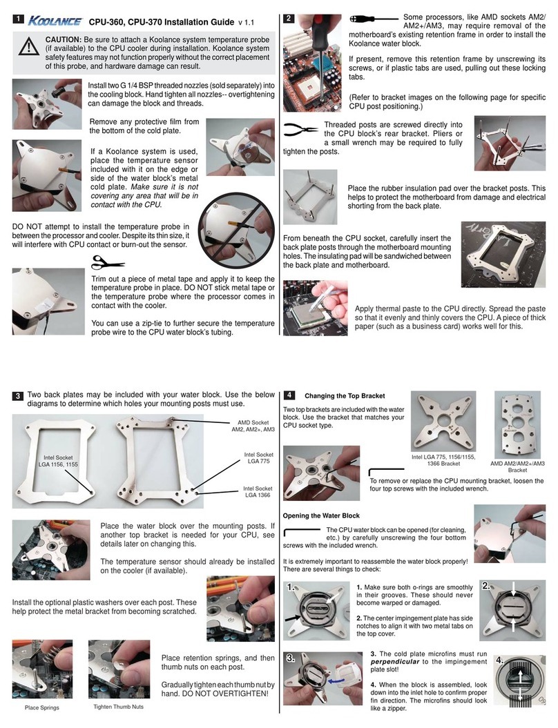
Koolance CPU-360 User manual

Koolance

Koolance CPU-360 User manual

Koolance ERM-3K4U User manual

Koolance

Koolance ERM-3K4U User manual

Koolance TMS-100K User manual

Koolance

Koolance TMS-100K User manual

Koolance Exos-2 User manual

Koolance

Koolance Exos-2 User manual

Koolance EXC-900 User manual

Koolance

Koolance EXC-900 User manual

Koolance ALX Series User manual

Koolance

Koolance ALX Series User manual

Koolance RP-1250 User manual

Koolance

Koolance RP-1250 User manual

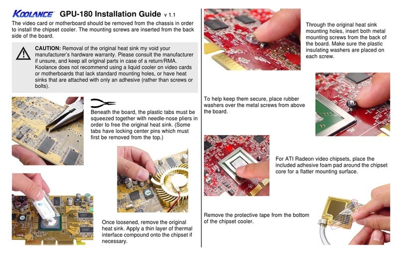
Koolance GPU-180 User manual

Koolance

Koolance GPU-180 User manual

Koolance PC4-1000 User manual

Koolance

Koolance PC4-1000 User manual

Koolance EXC-800 User manual

Koolance

Koolance EXC-800 User manual

Popular Computer Hardware manuals by other brands

Vitek VTQ-B04 Specifications

Vitek

Vitek VTQ-B04 Specifications

National Semiconductor CP3BT26 user manual

National Semiconductor

National Semiconductor CP3BT26 user manual

Cross Technologies 1200-04 instruction manual

Cross Technologies

Cross Technologies 1200-04 instruction manual

Adeunis RF ARF8020AA user guide

Adeunis RF

Adeunis RF ARF8020AA user guide

Texas Instruments OMAP35 Series user guide

Texas Instruments

Texas Instruments OMAP35 Series user guide

Avenview DVI-SPLITPRO-4X user guide

Avenview

Avenview DVI-SPLITPRO-4X user guide

LOVATO ELECTRIC EXP10 12 instruction manual

LOVATO ELECTRIC

LOVATO ELECTRIC EXP10 12 instruction manual

ekwb EK-FB ASUS R5-E10 Installation and mounting manuals

ekwb

ekwb EK-FB ASUS R5-E10 Installation and mounting manuals

Areca ARC-12 6 Series Quick installation guide

Areca

Areca ARC-12 6 Series Quick installation guide

Texas Instruments TVP5158 user guide

Texas Instruments

Texas Instruments TVP5158 user guide

IEI Technology KINO-AH611 Quick installation guide

IEI Technology

IEI Technology KINO-AH611 Quick installation guide

ActionTec 54 Mbps Wireless PC Card user guide

ActionTec

ActionTec 54 Mbps Wireless PC Card user guide

Alto Verb user manual

Alto

Alto Verb user manual

Nvidia Quadro M6000 Sync user guide

Nvidia

Nvidia Quadro M6000 Sync user guide

Intel SASUC8I - RAID Controller Hardware user's guide

Intel

Intel SASUC8I - RAID Controller Hardware user's guide

Disc Makers Reflex10 user guide

Disc Makers

Disc Makers Reflex10 user guide

swiftech MCX370-A installation guide

swiftech

swiftech MCX370-A installation guide

Premier Farnell Embest SBC-PH8700 user manual

Premier Farnell

Premier Farnell Embest SBC-PH8700 user manual

manuals.online logo
manuals.online logoBrands
  • About & Mission
  • Contact us
  • Privacy Policy
  • Terms and Conditions

Copyright 2025 Manuals.Online. All Rights Reserved.