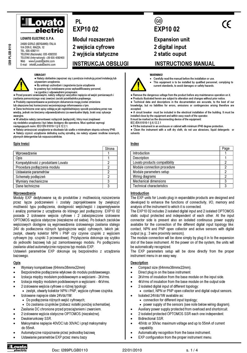
LOVATO ELECTRIC EXP10 12 User manual

стр. 1 / 3
EXP10 12 EXP10 12
Модуль расширения Expansion unit
интерфейс RS485 изолированный Isolated RS485 interface
ИНСТРУКЦИЯ ПО ЭКСПЛУАТУЦИИ INSTRUCTIONS MANUAL
● При проведение обслуживания устройства, отключите все напряжения
измерения и питания а такжже закоротите входы трансформаторов тока.
● Прибор может быть модифицирован производителем без предварительного
уведомления.
● Технические данные иописания представленные вданной инструкции
служат для пояснения ине дают гарантия от ошибок, случайностей и
непредвиденных обстоятельств.
● Очистка прибора производиться сухой мягкой тканью без использования
абразива иагрессивных жидкостей.
● Remove the dangerous voltage from the product before any maintenance
operation on it.
●Products illustrated herein are subject to alteration and changes without prior
notice.
● Technical data and descriptions in the documentation are accurate, to the best
of our knowledge, but no liabilities for errors, omissions or contingencies arising
therefrom are accepted.
● Clean the instrument with a soft dry cloth, do not use abrasives, liquid
detergents or solvents
Оглавление
Стр.
Введение
1
Описание
1
Совместимость продуктов Lovato
1
Процедура присодинения модуля
2
Установка параметров
2
Схемы присоединения
2
Размеры
3
Технические характеристики
3
Index
Page
Introduction
1
Description
1
Lovato products compatibility
1
Module connection procedure
2
Module parameters setup
2
Wiring diagrams
2
Mechanical dimensions
3
Technical characteristics
3
Введение
Модули расширения серии EXP разработаны для увеличения функций
связи, I/O, памяти ианализа приборов измерения.
Модуль EXP10 12 снабжен изолированным серийным интерфейсом
RS 485 и может присоединяться к базовому прибору путем установки
в разъем. При подаче напряжения питания на систему, база
автоматически опознает модуль, настройка модуля EXP
производиться из меню базового прибора простым путем.
Introduction
The EXP units for Lovato plug in expandable products are designed and
developed to enhance the functions of connectivity, I/O, memory and
analysis of the instrument to which it is connected.
The EXP10 12 implements the isolated RS485 serial interface and its
connection will be done simply by plug it in to the expansion slot of the
base instrument. At the power on of the system, the instrument will
automatically recognize the units and the EXP parameters setup will be
done directly from the proper instrument menu in an easy way.
Описание
Компактный размер (64mmx38mmx22mm)
Прямая установка на базовый прибор.
Стойкость изоляции 4KVrms для 1минуты между базой.
RS 485 серийный интерфейс
Программируемая скорость до 38400 Bps
Автоматическое опознание базовым прибором
EMP конфигурация через меню базового прибора
Присоединение к ПК кабелем Lovato. Код 51С2.
Description
Compact size (64mmx38mmx22mm).
Direct plug in on the base instrument.
4KVrms for 1 minute of insulation from the base module.
RS485 communication interface.
Programmable bitrates up to 38400Bps.
Automatically recognition from the instrument to which is
connected.
EXP configuration from the proper instrument menu.
Connection to the PC using the Lovato cable Cod. 51C2.
Совместимость продуктов Lovato
Модули расширения EXP10 12 может присоединяться кдругим
продуктам Lovato снабженными EXP разъемом. Проверьте
совместимость с устройствами Lovato согласно инструкции по
эксплуатации.
Lovato products compatibility
EXP10 12 expansion unit can be connected to a Lovato product fitted by
EXP plug in receptacle slot. Verify the compatibility with the base product
from its manual.
Процедура присоединения модулей
Module connection procedure
I295 RU GB 1109
ВНИМАНИЕ!!
●Внимательно прочтите инструкцию преред применением и
установкой .
●Данное оборудование должно устанавливаться
квалифицированным персоналом, согласно стандартам во
избежание несчастных случаев и аварий.
WARNING!
Carefully read the manual before the installation or use.
This equipment is to be installed by qualified personnel,
complying to current standards, to avoid damages or safety
hazards.

стр. 2 / 3
1. Отключите напряжение.
2. Удалите крышки и блокировки разъемов.
3. Удалите заглушку разъема ирасположите модуль сразъемом
так, чтобы его можно было вставить в разъем.
4. Вставьте верхнюю защелку модуля EXP10 12 вотверстие базы
находящееся на верху корпуса и совместите разъемы, не
допуская выхода защелки из отверстия базы.
5. Небольшим круговым движение, завершите установку модуля
EXP до появления щелчка.
6. Установите на место крышки иблокировки разъемов.
7. Подайте напряжение на систему (прибор автоматически опознает
модуль).
8. Сконфигурируйте модуль, следуя описанию программирования в
инструкции по эксплуатации прибора.
ПРИМЕЧАНИЕ: при извлечении модуля EXP (напряжение отключено
ивынуты все возможные блокировки икрышки разъемов, которые
могут препятствовать извлечению), нажмите на точку, обозначенную *
и выньте модуль.
1. Remove any dangerous voltage.
2. Remove the terminal covers and the terminal block.
3. Remove the expansion slot cover of the Lovato product at the
position in which the EXP will be plug in.
4. Insert the EXP10 12 so that its upper hook enters into the
hole present above the expansion slot playing in this way the
function of pivot during insertion.
5. Bring the EXP at the complete insertion by a little circular
motion.
6. Re-position the terminal block and the terminal cover.
7. Power up the system (the base product will automatically
recognize the expansion unit).
8. Configure the module by following the programming indication
presents on the instrument manual.
NOTE: in order to pull out the EXP (having removed the dangerous
voltage and possible terminal blocks which hinder the removal) press the
point indicated by the * and extract the module.
Установка параметров
Для установки параметров конфигурации, смотрите инструкцию по
эксплуатации базового прибора.
Module parameters setup
For the EXP parameters configuration, see the manual of the main
instrument to which it intends to connect.
Схемы присоединений
Wiring diagrams
EXP10 12 n°1EXP10 12 n°31
SGTR BA
RS485
TR BA SG
RS485
PX1
ATR BSG
PC
CLAC!
1
2
3
*
ВНИМАНИЕ!
●Когда модуль EXP установлен на прибор серии
DMG, обязательно установите опечатываемые крышки
разъмов, поставляемые смультиметром.
WARNING!
When the EXP.. module is installed on a DMG series
multimeter, it is mandatory to install the sealable
terminal block covers supplied with the multimeter.

стр. 3 / 3
Размеры[mm]
Mechanical dimensions [mm]
Скорость
Программируемая1200 - 38400
bps
Baud-rate
Programmable 1200…38400 bps
Напряжение изоляции
Insulation voltage
Импульсное напряжение изоляции Uimp
7,3kV
Rated impulse withstand voltage Uimp
7,3kV
Частотное напряжение изоляции
4kV
Power frequency withstand voltage
4kV
Рабочие условия
Ambient operating conditions
Рабочая температура
-20 - +60°C
Operating temperature
-20 - +60°C
Температура хранения
-30 - +80°C
Storage temperature
-30 - +80°C
Влажность
90%
Relative humidity
90%
Степень загрязнения
Класс 2
Maximum pollution degree
Degree 2
Категория перенапряжения
3
Overvoltage category
3
Высота над уровнем моря
≤2000m
Altitude
≤2000m
Размеры
64,5mmx38,2mmx22mm
Dimensions
64.5mmx38.2mmx22mm
Крепление
Для установки в разъем EXP
Mounting
For inclusion in the EXP plug in
expansion slot
Материал
Полиамид RAL 7035
Material
Polyamide RAL7035
Степень защиты
IP20
Degree of protection
IP20
Вес
55g
Weight
55g
Технические характеристики
Technical characteristics
Интерфейс RS485
RS485 Serial interface
Присоединение порта RS485
RS485 port connection
Присоединение
Втычное
Connection
Plug in/Removable termina type
Количество клемм
4
Number of terminals
4
Сечение кабеля (min иmax)
0,2...1,5 mmq (2814 AWG)
Cable cross section (min… max)
0.2…1.5 mm² (24…12 AWG)
Усилие затяжки
0,18 Nm (1,7 LBin)
Tightening torque
0.18 Nm (1.7 lbin)
Присоединение к базе
Base product connection
Тип присоединения
Втычное
Terminal type
Plug-in connector
Корпус
Housing
Сертификация и соответствие
Certifications and compliance
Стандарты
IEC/EN 61010-1:2001, IEC/EN 61000-6-2:2005,
EN 61000-4-3:2006, EN 61000-6-3:2001,
IEC/EN 60068-2-61:1993, IEC/EN 60068-2-78,
IEC/EN 60068-2-6, IEC 60068-2-27.
Reference standards
IEC/EN 61010-1:2001, IEC/EN 61000-6-2:2005,
EN 61000-4-3:2006, EN 61000-6-3:2001,
IEC/EN 60068-2-61:1993, IEC/EN 60068-2-78,
IEC/EN 60068-2-6, IEC 60068-2-27
Repeat this wiring diagram
Set as repeater
B
up to 255 devices
PX1
BTR ASG TR A
Device addresses n° 31-60
SG
EXM10 12
B
RS485
TR ASG
Set as repeater
PX1
TR ASGBTR ASGBB
EXM10 12
Device addresses n° 1-30
B
RS485
TR ASG TR A
PX1
SG
PC
Table of contents
Other LOVATO ELECTRIC Computer Hardware manuals
Popular Computer Hardware manuals by other brands

Raidon
Raidon SafeTANK GR3680-SB3 user manual

Vreo Innovation
Vreo Innovation Vreo Unity Technical manual

Disc Makers
Disc Makers Reflex4 quick start guide

IEI Technology
IEI Technology HPE-8S0 Quick installation guide

Texas Instruments
Texas Instruments SimpleLink Wi-Fi CC3 20 Series user guide

Asus
Asus ROG RYUJIN II Series quick start guide