Premier Farnell Embest SBC-PH8700 User manual

SBC-PH8700 User Manual
Embest Technology Co. Ltd | http://www.embest-tech.com 1
User Manual
[SBC-PH8800]

SBC-PH8700 User Manual
Embest Technology Co. Ltd | http://www.embest-tech.com 2
Revision History
Rev.
Note
Author
20160902
Initial
Sandy

SBC-PH8700 User Manual
Embest Technology Co. Ltd | http://www.embest-tech.com 3
Catalog
Revision History ........................................................................................................................................................... 2
Catalog ......................................................................................................................................................................... 3
Release Note................................................................................................................................................................ 5
1. Images Version............................................................................................................................................. 5
2. Feature List .................................................................................................................................................. 5
3. Known Issues ............................................................................................................................................... 6
Chapter 1 Quick Start ............................................................................................................................................... 7
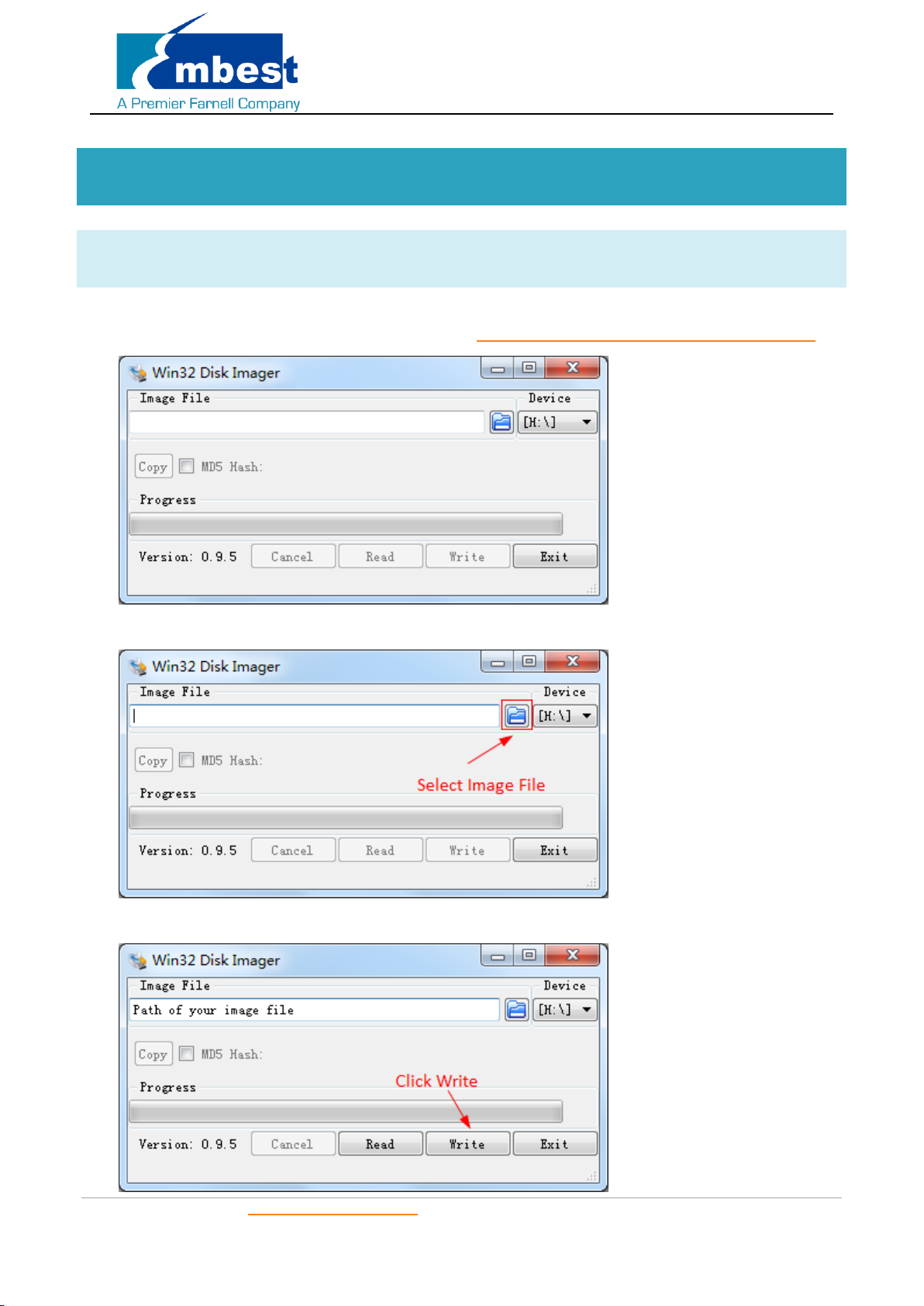
1.1 Burn the System Images to the SD Card .................................................................................................. 7
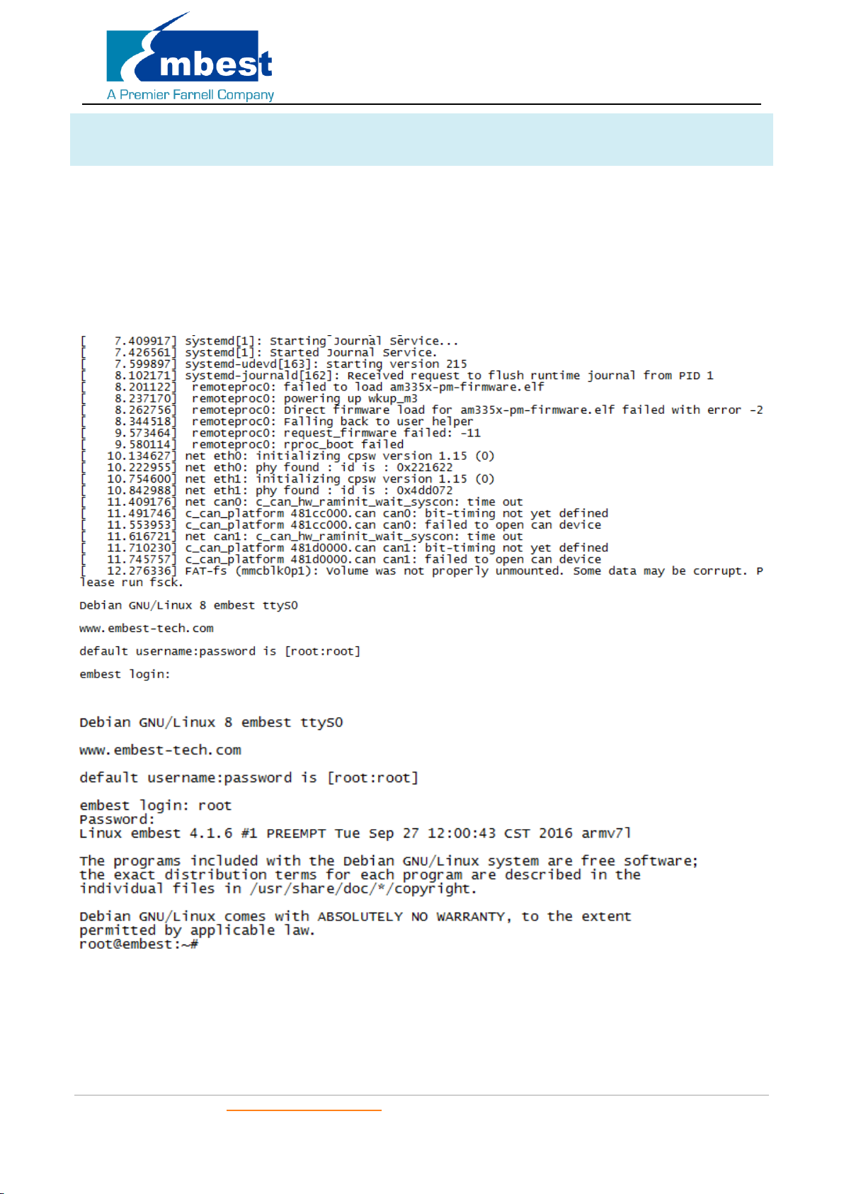
1.2 System Boot from SD Card....................................................................................................................... 8
1.3 System Boot from SPI Flash ..................................................................................................................... 9
Chapter 2 Function test .......................................................................................................................................... 11
2.1 LED ......................................................................................................................................................... 11
2.2 RTC ......................................................................................................................................................... 11
2.3 EEPROM ................................................................................................................................................. 12
2.4 EMMC .................................................................................................................................................... 13
2.5 ADC ........................................................................................................................................................ 13
2.6 HDMI...................................................................................................................................................... 14
2.7 HDMI Audio ........................................................................................................................................... 14
2.8 LCD......................................................................................................................................................... 14
2.9 Backlight................................................................................................................................................. 14
2.10 Touchscreen........................................................................................................................................... 14
2.11 Serial ...................................................................................................................................................... 15
2.11.1 UART1 ........................................................................................................................................ 15
2.11.2 UART2 ........................................................................................................................................ 15
2.11.3 UART4 ........................................................................................................................................ 16
2.12 RS485 ..................................................................................................................................................... 17
2.12.1 RS485-2 and RS485-3................................................................................................................. 17
2.13 CAN ........................................................................................................................................................ 17
2.14 Network ................................................................................................................................................. 18
2.15 USB......................................................................................................................................................... 19
2.15.1 USB Host .................................................................................................................................... 19
2.15.2 OTG Test ..................................................................................................................................... 19

SBC-PH8700 User Manual
Embest Technology Co. Ltd | http://www.embest-tech.com 4
2.16 Camera................................................................................................................................................... 21
2.16.1 Video.......................................................................................................................................... 21
2.16.2 Photo.......................................................................................................................................... 21
Chapter 3 System Compilation ............................................................................................................................... 22
3.1 Building Development Environment...................................................................................................... 22
3.2 Compiling U-Boot................................................................................................................................... 22
3.2.1 Get the U-Boot Source Code...................................................................................................... 22
3.2.2 Compile and Burn the Images to SD Card.................................................................................. 22
3.2.3 Compile and Burn the Images to SPI Flash ................................................................................ 22
3.3 Compiling Kernel.................................................................................................................................... 23
3.3.1 Get Kernel Source Code ............................................................................................................. 23
3.3.2 Compile and Burn the Images to SD Card.................................................................................. 23

SBC-PH8700 User Manual
Embest Technology Co. Ltd | http://www.embest-tech.com 5
Release Note
1. Images Version
SBC-PH8800_Shipment_Image_SDCard_Rev01.img
SBC-PH8800_Shipment_Image_EMMC_Rev01.img
2. Feature List
Feature List
SBC-PH8800
Schematic
Page#
On-Chip
Peripherals
On-Board
Peripherals
Detail Functions(existing)
u-boot version
2015.09
Supports kernel boot
kernel version
4.1.6
Supports all below functionality
Filesystem
Debian
Default root file system used by
debian
CPU
PH8800-U11
AM437X_ZDN
Null
DDRAM
PH8800-p7-u12/u7
DDR
MT41K256M16HA-125
Can access read write and run
code
PMIC
PH8800-p3-u13
I2C0
TPS65218
Null
MicroSD_(TF)
SPH1800-P6-TF1
MMC0
Null
Can access read write and boot
External-RTC
SPH1800-P9-U55
I2C0
RX-8025TUB
can read write and keep time off
power
Integrited-RTC
PH8800-u11
RTC
Null
can read write and keep time off
power
LEDs
PH8800-p10-D3/D
4
gpio
Null
System can control LED to light or
not
Power-Button
PH1800-P14-S2
I2C0
TPS65218
Can get key value
LCD
SPH1800-P9-J9
RGB
Null
Can show picture on the screen
Backlight
SPH1800-P9-J9
PWM
Null
System can control the LCD
backlight
TouchScreen
SPH1800-P9-J9
ADC-TSC
Null
System use touchscreen
eMMC
PH8800-p8-u14
MMC1
MTFC4GACAAAM-4M
IT
Can access read write
EEPROM
PH8800-p8-u6
I2C0
CAT24C256W
Can access read write
SPI-FLASH
PH8800-p8-u3
QSPI
N25Q256A13EF840
1. Boot from SPI-Flash

SBC-PH8700 User Manual
Embest Technology Co. Ltd | http://www.embest-tech.com 6
CAN-1
SPH1800-p8-J61
CAN1
MC33901WEF
System can send and receive data
between two board
CAN-2
SPH1800-p8-J61
CAN0
MC33901WEF
System can send and receive data
between two board
UART-0
SPH1800-p7-CN4
UART0
NUll
System can send and receive data
in loopback mode
UART-1
SPH1800-p7-J4
UART5
MAX3232CUE+
System can send and receive data
in loopback mode
UART-2
SPH1800-p13-J58
UART3
Null
System can send and receive data
in loopback mode
UART-4
SPH1800-p13-J58
UART1
MAX3232CUE+
System can send and receive data
in loopback mode
RS485-2
SPH1800-p8-u5
SPI0
SC16IS752IPW
System can send and receive data
between two board
RS485-3
SPH1800-p8-u5
SPI0
SC16IS752IPW
System can send and receive data
between two board
USB-Host
SPH1800-p11-p3
USB1
Null
Can recognize U disk by USB host
CAMERA
SPH1800-p9j8
CSI&I2C1
Null
Could preview, take picture and
record video
USB-OTG
SPH1800-p11-j13
USB0
Null
Can recognize U disk in host
mode, and can work as usb
ethernet in device mode
Ethernet-1
PH8800-P9-U9
RGMII1
KSZ9031RNXIA
Can ping the server
Ethernet-2
SPH1800-P12-J17
RGMII2
AR8035
Can ping the server
HDMI
SPH1800-P10-U34
I2C0
TDA19988BHN/C1,551
Can show picture on the screen
Audio
SPH1800-P10-U34
I2C0
TDA19988BHN/C1,551
can play wav
3. Known Issues
Known issue List
Detail
SPI-FLASH
Not Support: SPI-Flash access in kernel
Ethernet-1 & Ethernet
-2
Bug: Board to board connect under high or low temperature environment could not working
normally
LCD
Bug:4.3 inch Screen turn white for a while in boot
HDMI Audio
Not support Sony HDMI displayer

SBC-PH8700 User Manual
Embest Technology Co. Ltd | http://www.embest-tech.com 7
Chapter 1 Quick Start
1.1 Burn the System Images to the SD Card
Firstly, you should prepare a SD card, which is no less than 2GB.
Then, download and install “Win32 Disk Imager”from https://sourceforge.net/projects/win32diskimager/.
Select the system image: SBC-PH8800_Shipment_Image_SDCard_Rev01.img:
Click “Write”button to burn the images:

SBC-PH8700 User Manual
Embest Technology Co. Ltd | http://www.embest-tech.com 8
1.2 System Boot from SD Card
Install the Serial Communication software (e.g. SecureCRT), select the corresponding port number, baudrate
as 115200, data bits as 8, stop bits as 1, parity as none.
Connect the DEBUG interface (CN4) to the serial interface of PC with a USB to TTL module.
Insert the MicroSD card into the card slot (TF1).
Press S3 button, then powered the board with a 5V, 2A power. Release S3 after the power reset.
Wait for the system boot up, then the serial output will show the following information:
Enter username and password as “root”to login;

SBC-PH8700 User Manual
Embest Technology Co. Ltd | http://www.embest-tech.com 9
1.3 System Boot from SPI Flash
Refer to 1.2, boot the system from SD Card, press “Enter”when the serial terminal prints the following info:
U-Boot SPL 2015.07 (Sep 27 2016 - 11:42:48)
SPL: Please implement spl_start_uboot() for your board
SPL: Direct Linux boot not active!
reading u-boot.img
reading u-boot.img
U-Boot 2015.07 (Sep 27 2016 - 11:42:48 +0800)
I2C: ready
DRAM: 1 GiB
PMIC: TPS65218
MMC: OMAP SD/MMC: 0, OMAP SD/MMC: 1
reading uboot.env
** Unable to read "uboot.env" from mmc0:1 **
Using default environment
Net: <ethaddr> not set. Validating first E-fuse MAC
cpsw, usb_ether
Hit any key to stop autoboot: 0
U-Boot# (Press Enter now.)
Execute the following instructions on the serial terminal:
U-Boot# run update_qspi_flash
switch to partitions #0, OK
mmc0 is current device
SD/MMC found on device
reading u-boot-spl.bin
56904 bytes read in 6 ms (9 MiB/s)
SF: Detected N25Q256 with page size 256 Bytes, erase size 4 KiB, total 32 MiB, mapped at 30000000
SF: 589824 bytes @ 0x0 Erased: OK
device 0 offset 0x0, size 0xde48
SF: 56904 bytes @ 0x0 Written: OK
reading u-boot.bin

SBC-PH8700 User Manual
Embest Technology Co. Ltd | http://www.embest-tech.com 10
288632 bytes read in 17 ms (16.2 MiB/s)
device 0 offset 0x20000, size 0x46778
SF: 288632 bytes @ 0x20000 Written: OK
U-Boot#
Enter following instruction to boot from SD Card first:
U-Boot# boot
Copy the SBC-PH8800_Shipment_Image_EMMC_Rev01.img to a U-disk, then plug the U-disk to P3;
Execute the following instructions on the serial terminal:
root@ SOM-PH8800:~# ls /dev/sd*
/dev/sda /dev/sda1
root@ SOM-PH8800:~# mount /dev/sda1 /mnt/
root@ SOM-PH8800:~# dd if=/mnt/SBC-PH8800_Shipment_Image_EMMC_Rev01.img of=/dev/mmcblk1
Note: Burn the EMMC takes a long time, please wait patiently.
Then power reset the board to boot from EMMC (Don’t press S3 anymore).

SBC-PH8700 User Manual
Embest Technology Co. Ltd | http://www.embest-tech.com 11
Chapter 2 Function test
First of all, please refer to Chapter 1.1 and boot up the system. Then test the functions according to the following
guidance.
2.1 LED
User can control LED (D3, D4) indicators on SOM-PH8800 Board. After the system boot up, please execute the
following instructions in serial terminal to implement the test; (D3 is attached to user_leds_d3, D4 to
user_leds_d4)
Light out LED:
root@embest:~# echo 0 > /sys/class/leds/user_leds_d3/brightness
root@embest:~# echo 0 > /sys/class/leds/user_leds_d4/brightness
Light up LED:
root@embest:~# echo 1 > /sys/class/leds/user_leds_d3/brightness
root@embest:~# echo 1 > /sys/class/leds/user_leds_d4/brightness
2.2 RTC
Execute the following instructions on the serial terminal:
Check the current system time:
root@embest:~# date
Sat Jan 1 00:02:07 UTC 2000
Set current time as 10:46, March 9, 2016
root@embest: # date 030910462016
Wed Mar 9 10:46:00 UTC 2016
Write system clock into RTC:
root@embest: # hwclock –w
Read RTC value:
root@embest: # hwclock
Wed 09 Mar 2016 10:46:23 AM UTC -0.432561 seconds
The above information indicates that the hardware clock-RTC-has been set to March 9, 2016, so the system clock
is saved in the hardware clock.
Reboot the system and check the current system time:
root@embest:~# date
Wed Mar 9 10:46:45 UTC 2016

SBC-PH8700 User Manual
Embest Technology Co. Ltd | http://www.embest-tech.com 12
2.3 EEPROM
Execute the following instructions on the serial terminal:
root@embest:~# ./eeprom_test
data will write to EEPROM at 0x400
00 01 02 03 04 05 06 07 08 09 0a 0b 0c 0d 0e 0f
10 11 12 13 14 15 16 17 18 19 1a 1b 1c 1d 1e 1f
20 21 22 23 24 25 26 27 28 29 2a 2b 2c 2d 2e 2f
30 31 32 33 34 35 36 37 38 39 3a 3b 3c 3d 3e 3f
40 41 42 43 44 45 46 47 48 49 4a 4b 4c 4d 4e 4f
50 51 52 53 54 55 56 57 58 59 5a 5b 5c 5d 5e 5f
60 61 62 63 64 65 66 67 68 69 6a 6b 6c 6d 6e 6f
70 71 72 73 74 75 76 77 78 79 7a 7b 7c 7d 7e 7f
80 81 82 83 84 85 86 87 88 89 8a 8b 8c 8d 8e 8f
90 91 92 93 94 95 96 97 98 99 9a 9b 9c 9d 9e 9f
a0 a1 a2 a3 a4 a5 a6 a7 a8 a9 aa ab ac ad ae af
b0 b1 b2 b3 b4 b5 b6 b7 b8 b9 ba bb bc bd be bf
c0 c1 c2 c3 c4 c5 c6 c7 c8 c9 ca cb cc cd ce cf
d0 d1 d2 d3 d4 d5 d6 d7 d8 d9 da db dc dd de df
e0 e1 e2 e3 e4 e5 e6 e7 e8 e9 ea eb ec ed ee ef
f0 f1 f2 f3 f4 f5 f6 f7 f8 f9 fa fb fc fd fe ff
data read from EEPROM at 0x400
00 01 02 03 04 05 06 07 08 09 0a 0b 0c 0d 0e 0f
10 11 12 13 14 15 16 17 18 19 1a 1b 1c 1d 1e 1f
20 21 22 23 24 25 26 27 28 29 2a 2b 2c 2d 2e 2f
30 31 32 33 34 35 36 37 38 39 3a 3b 3c 3d 3e 3f
40 41 42 43 44 45 46 47 48 49 4a 4b 4c 4d 4e 4f
50 51 52 53 54 55 56 57 58 59 5a 5b 5c 5d 5e 5f
60 61 62 63 64 65 66 67 68 69 6a 6b 6c 6d 6e 6f
70 71 72 73 74 75 76 77 78 79 7a 7b 7c 7d 7e 7f
80 81 82 83 84 85 86 87 88 89 8a 8b 8c 8d 8e 8f
90 91 92 93 94 95 96 97 98 99 9a 9b 9c 9d 9e 9f
a0 a1 a2 a3 a4 a5 a6 a7 a8 a9 aa ab ac ad ae af
b0 b1 b2 b3 b4 b5 b6 b7 b8 b9 ba bb bc bd be bf
c0 c1 c2 c3 c4 c5 c6 c7 c8 c9 ca cb cc cd ce cf
d0 d1 d2 d3 d4 d5 d6 d7 d8 d9 da db dc dd de df
e0 e1 e2 e3 e4 e5 e6 e7 e8 e9 ea eb ec ed ee ef

SBC-PH8700 User Manual
Embest Technology Co. Ltd | http://www.embest-tech.com 13
f0 f1 f2 f3 f4 f5 f6 f7 f8 f9 fa fb fc fd fe ff
If write and read data are the same, the test passes.
2.4 EMMC
Execute the following instructions on the serial terminal:
root@embest:~# touch emmc_read emmc_write
Modify emmc_write value:
root@embest:~# vi emmc_write
E.g. Write “emmc write test”into the system
Write emmc instructions:
root@embest:~# dd if=emmc_write of=/dev/mmcblk1
[ 929.393325] mmcblk1: p1 p2
0+1 records in
0+1 records out
17 bytes (17 B) copied, 0.135215 s, 0.1 kB/s
Read emmc instructions:
root@embest:~# dd if=/dev/mmcblk1 of=emmc_read bs=1K count=10
10+0 records in
10+0 records out
10240 bytes (10 kB) copied, 0.00446492 s, 2.3 MB/s
Check emmc_read value:
root@embest:~# cat emmc_read
emmc write test
Test passes;
2.5 ADC
Execute the following instructions on the serial terminal to get the sampling values returned:
root@embest:~# cat /sys/bus/platform/devices/TI-am335x-adc/iio\:device0/in_voltage4_raw
603
root@embest:~# cat /sys/bus/platform/devices/TI-am335x-adc/iio\:device0/in_voltage5_raw
599
root@embest:~# cat /sys/bus/platform/devices/TI-am335x-adc/iio\:device0/in_voltage6_raw
767
root@embest:~# cat /sys/bus/platform/devices/TI-am335x-adc/iio\:device0/in_voltage7_raw
847

SBC-PH8700 User Manual
Embest Technology Co. Ltd | http://www.embest-tech.com 14
2.6 HDMI
Open the uEnv.txt file from SD card, modify fdtfile=embest-SOM_PH8800-BB_SPH1800-HDMI.dtb
Connect the display with HDMI cable, then reboot the system;
2.7 HDMI Audio
Connect the HDMI device, execute the following instruction to play the default audio file:
root@embest:~# aplay /boot/firmware/audio_sample.wav
Playing WAVE '/boot/firmware/audio_sample.wav' : Signed 16 bit Little Endian, Rate 22050 Hz, Stereo
2.8 LCD
4.3” LCD:
Open the uEnv.txt file from SD card, modify fdtfile= embest-SOM_PH8800-BB_SPH1800-4.3inch_LCD.dtb
Connect the screen module to J9, then reboot the system.
7” LCD:
Open the uEnv.txt file from SD card, modify fdtfile= embest-SOM_PH8800-BB_SPH1800-7inch_LCD.dtb
Connect the screen module to J9, then reboot the system.
2.9 Backlight
The backlight brightness has a range from 1 to 8, in which 8 means highest brightness, 1 means lowest.
Execute the following instructions on the serial terminal to implement the backlight test:
The darkest:
root@embest:~# echo 1 > /sys/class/backlight/backlight/brightness
The brightest:
root@embest:~# echo 8 > /sys/class/backlight/backlight/brightness
2.10 Touchscreen
Connect the screen module to J9, execute the following instructions on the serial terminal to implement the touch
screen calibration program:
root@embest:~# ts_calibrate
Following the notes on LCD, click the “+”icon for five times to complete the calibration.

SBC-PH8700 User Manual
Embest Technology Co. Ltd | http://www.embest-tech.com 15
2.11 Serial
The board has 4 serial interfaces, while the UART0 (CN4) is the debug interface. Execute the following instructions
on the serial terminal to test UART 1, UART2 and UART4:
2.11.1UART1
Short Pin 2 and 3 in J4:
root@embest:~# ./uart_test -d /dev/ttyS5 -b 115200
/dev/ttyS5 SEND: 1234567890
/dev/ttyS5 RECV 1 total
/dev/ttyS5 RECV: 1
/dev/ttyS5 RECV 1 total
/dev/ttyS5 RECV: 2
/dev/ttyS5 RECV 1 total
/dev/ttyS5 RECV: 3
/dev/ttyS5 RECV 1 total
/dev/ttyS5 RECV: 4
/dev/ttyS5 RECV 1 total
/dev/ttyS5 RECV: 5
/dev/ttyS5 RECV 1 total
/dev/ttyS5 RECV: 6
/dev/ttyS5 RECV 1 total
/dev/ttyS5 RECV: 7
/dev/ttyS5 RECV 1 total
/dev/ttyS5 RECV: 8
/dev/ttyS5 RECV 1 total
/dev/ttyS5 RECV: 9
/dev/ttyS5 RECV 1 total
/dev/ttyS5 RECV: 0
2.11.2UART2
Short Pin 16 and 17 in J58:
root@embest:~# ./uart_test -d /dev/ttyS3 -b 9600
/dev/ttyS3 SEND: 1234567890
/dev/ttyS3 RECV 1 total
/dev/ttyS3 RECV: 1
/dev/ttyS3 RECV 1 total
/dev/ttyS3 RECV: 2

SBC-PH8700 User Manual
Embest Technology Co. Ltd | http://www.embest-tech.com 16
/dev/ttyS3 RECV 1 total
/dev/ttyS3 RECV: 3
/dev/ttyS3 RECV 1 total
/dev/ttyS3 RECV: 4
/dev/ttyS3 RECV 1 total
/dev/ttyS3 RECV: 5
/dev/ttyS3 RECV 1 total
/dev/ttyS3 RECV: 6
/dev/ttyS3 RECV 1 total
/dev/ttyS3 RECV: 7
/dev/ttyS3 RECV 1 total
/dev/ttyS3 RECV: 8
/dev/ttyS3 RECV 1 total
/dev/ttyS3 RECV: 9
/dev/ttyS3 RECV 1 total
/dev/ttyS3 RECV: 0
2.11.3UART4
Short Pin 14 and 15 in J58:
root@embest:~# ./uart_test -d /dev/ttyS1 -b 9600
/dev/ttyS1 SEND: 1234567890
/dev/ttyS1 RECV 1 total
/dev/ttyS1 RECV: 1
/dev/ttyS1 RECV 1 total
/dev/ttyS1 RECV: 2
/dev/ttyS1 RECV 1 total
/dev/ttyS1 RECV: 3
/dev/ttyS1 RECV 1 total
/dev/ttyS1 RECV: 4
/dev/ttyS1 RECV 1 total
/dev/ttyS1 RECV: 5
/dev/ttyS1 RECV 1 total
/dev/ttyS1 RECV: 6
/dev/ttyS1 RECV 1 total
/dev/ttyS1 RECV: 7
/dev/ttyS1 RECV 1 total
/dev/ttyS1 RECV: 8
/dev/ttyS1 RECV 1 total

SBC-PH8700 User Manual
Embest Technology Co. Ltd | http://www.embest-tech.com 17
/dev/ttyS1 RECV: 9
/dev/ttyS1 RECV 1 total
/dev/ttyS1 RECV: 0
Note: Press “CTRL+C”to exit the serial test.
2.12 RS485
2.12.1RS485-2 and RS485-3
Short connect Pin 7 and 9, Pin 8 and 10 in J62 (That is RS485-A3 to RS485-A2, RS485-B3 to RS485-B2):
Execute the following instructions on the serial terminal (in the background):
root@embest:~# ./uart_test -d /dev/ttySC1 -b 9600 -s "a" &
Then enter the following:
root@embest:~# ./uart_test -d /dev/ttySC0 -b 9600 -s "c"
/dev/ttySC0 SEND: c
/dev/ttySC1 RECV 1 total
/dev/ttySC1 RECV: c
/dev/ttySC1 SEND: a
/dev/ttySC0 RECV 1 total
/dev/ttySC0 RECV: a
TtySC0, ttySC1 will send data separately, receive data correctly;
2.13 CAN
SBC-PH8800 support 2 CAN module, so we can use the on board CAN0 & CAN1 to test. Connect Pin1 and 3, Pin 2
and 4 in J62. Test method as below:
1. Open Can0 & CAN1
root@embest:~# ip link set can0 type can bitrate 50000 triple-sampling on
root@embest:~# ip link set can1 type can bitrate 50000 triple-sampling on
root@embest:~# ip link set can0 up
[ 116.797032] c_can_platform 481cc000.can can0: setting BTR=1c1d BRPE=0000
root@embest:~# ip link set can1 up
[ 116.860898] c_can_platform 481d0000.can can1: setting BTR=1c1d BRPE=0000
2. Transmit and receive data
CAN1 receive, CAN0 send data to CAN1:
root@embest:~# candump can1&
root@embest:~# cansend can0 123#01020304050607
root@embest:~# can1 123 [7] 01 02 03 04 05 06 07

SBC-PH8700 User Manual
Embest Technology Co. Ltd | http://www.embest-tech.com 18
Use ps and kill command to exit the candump program, change to CAN0 receive, CAN1 send data to CAN0:
root@embest:~# candump can0&
root@embest:~# cansend can1 123#11121314151617
root@embest:~# can0 123 [7] 11 12 13 14 15 16 17
3. Shut off the device after test finished.
root@embest:~# ip link set can0 down
read: Network is down
root@embest:~# [ 409.786888] c_can_platform 481cc000.can can0: setting BTR=1c1d BRPE=0000
root@embest:~# ip link set can1 down
[ 415.503272] c_can_platform 481d0000.can can1: setting BTR=1c1d BRPE=0000
[2]+ Exit 1 candump can0
Users can do the transceiving test according to the above instructions, and set different baudrate to communicate.
Note you must shut off the device before set a different baudrate. Effective baudrate contains:
25KBPS (250000)
50KBPS (50000)
125KBPS (125000)
500KBPS (500000)
650KBPS (650000)
1MKBPS (1000000)
The board can communicate at the above baudrate, users can also test with other baudrate to see if the device
work too. The CAN module can also connect a CAN module from other board to test.
2.14 Network
Execute the following instructions on the serial terminal:
Configure the IP address:
root@embest:~# ifconfig eth0 192.168.2.64
Testing network interface:
root@embest:~# ping 192.168.2.1
To test eth1, you need to disconnect the cable with J17, connect the cable with the external ETH module, then use
the above instructions to test. (Change eth0 to eth1).

SBC-PH8700 User Manual
Embest Technology Co. Ltd | http://www.embest-tech.com 19
2.15 USB
2.15.1USB Host
Insert the U disk to the USB Host interface (P3); serial terminal will display the disk information:
[ 937.902749] usb 1-1.2: new high-speed USB device number 4 using xhci-hcd
[ 938.023750] usb 1-1.2: New USB device found, idVendor=058f, idProduct=6366
[ 938.030999] usb 1-1.2: New USB device strings: Mfr=1, Product=2, SerialNumber=3
[ 938.039779] usb 1-1.2: Product: Flash Card Reader/Writer
[ 938.046076] usb 1-1.2: Manufacturer: Generic
[ 938.050558] usb 1-1.2: SerialNumber: 058F63666438
[ 938.059201] usb-storage 1-1.2:1.0: USB Mass Storage device detected
[ 938.069433] scsi host3: usb-storage 1-1.2:1.0
[ 939.073423] scsi 3:0:0:0: Direct-Access Multiple Card Reader 1.00 PQ: 0 ANSI: 0
[ 939.551759] sd 3:0:0:0: [sda] 15515648 512-byte logical blocks: (7.94 GB/7.39 GiB)
[ 939.560184] sd 3:0:0:0: [sda] Write Protect is off
[ 939.568026] sd 3:0:0:0: [sda] No Caching mode page found
[ 939.575739] sd 3:0:0:0: [sda] Assuming drive cache: write through
[ 939.589938] sda: sda1
[ 939.600578] sd 3:0:0:0: [sda] Attached SCSI removable disk
Execute the following instructions on the serial terminal:
root@embest:~# ls /dev/sd*
/dev/sda
Storage nodes locate under /dev;
2.15.2OTG Test
2.15.2.1 1. MASTER DEVICE
Connect U disk to J13 with an OTG cable:
[ 880.127626] xhci-hcd xhci-hcd.0.auto: xHCI Host Controller
[880.134829] xhci-hcd xhci-hcd.0.auto: new USB bus registered, assigned bus number 3
[ 880.148726] xhci-hcd xhci-hcd.0.auto: hcc params 0x0238f06d hci version 0x100 quirks 0x00010010
[ 880.159328] xhci-hcd xhci-hcd.0.auto: irq 194, io mem 0x48390000
[ 880.167206] usb usb3: New USB device found, idVendor=1d6b, idProduct=0002
[ 880.175323] usb usb3: New USB device strings: Mfr=3, Product=2, SerialNumber=1
[ 880.183769] usb usb3: Product: xHCI Host Controller
[ 880.188905] usb usb3: Manufacturer: Linux 4.1.6+ xhci-hcd
[ 880.195618] usb usb3: SerialNumber: xhci-hcd.0.auto

SBC-PH8700 User Manual
Embest Technology Co. Ltd | http://www.embest-tech.com 20
[ 880.207218] hub 3-0:1.0: USB hub found
[ 880.218080] hub 3-0:1.0: 1 port detected
[ 880.222687] xhci-hcd xhci-hcd.0.auto: xHCI Host Controller
[ 880.233442] xhci-hcd xhci-hcd.0.auto: new USB bus registered, assigned bus number 4
[ 880.241707] usb usb4: We don't know the algorithms for LPM for this host, disabling LPM.
[ 880.252038] usb usb4: New USB device found, idVendor=1d6b, idProduct=0003
[ 880.260133] usb usb4: New USB device strings: Mfr=3, Product=2, SerialNumber=1
[ 880.268622] usb usb4: Product: xHCI Host Controller
[ 880.274473] usb usb4: Manufacturer: Linux 4.1.6+ xhci-hcd
[ 880.280171] usb usb4: SerialNumber: xhci-hcd.0.auto
[ 880.292998] hub 4-0:1.0: USB hub found
[ 880.299620] hub 4-0:1.0: 1 port detected
[ 880.532745] usb 3-1: new high-speed USB device number 2 using xhci-hcd
[ 880.673750] usb 3-1: New USB device found, idVendor=058f, idProduct=6366
[ 880.680830] usb 3-1: New USB device strings: Mfr=1, Product=2, SerialNumber=3
[ 880.689456] usb 3-1: Product: Flash Card Reader/Writer
[ 880.695612] usb 3-1: Manufacturer: Generic
[ 880.699948] usb 3-1: SerialNumber: 058F63666438
[ 880.713047] usb-storage 3-1:1.0: USB Mass Storage device detected
[ 880.724837] scsi host2: usb-storage 3-1:1.0
[ 881.733406] scsi 2:0:0:0: Direct-Access Multiple Card Reader 1.00 PQ: 0 ANSI: 0
[ 882.211615] sd 2:0:0:0: [sda] 15515648 512-byte logical blocks: (7.94 GB/7.39 GiB)
[ 882.220103] sd 2:0:0:0: [sda] Write Protect is off
[ 882.227790] sd 2:0:0:0: [sda] No Caching mode page found
[ 882.235398] sd 2:0:0:0: [sda] Assuming drive cache: write through
[ 882.249459] sda: sda1
[ 882.260011] sd 2:0:0:0: [sda] Attached SCSI removable disk.
Execute the following instructions on the serial terminal:
root@embest:~# ls /dev/sd*
/dev/sda
Storage nodes locate under /dev;
2.15.2.2 2. SLAVE DEVICE
Connect J13 to PC, open the device manager, and check if the following device is recognized:
Other manuals for Embest SBC-PH8700
1
Table of contents
Other Premier Farnell Computer Hardware manuals