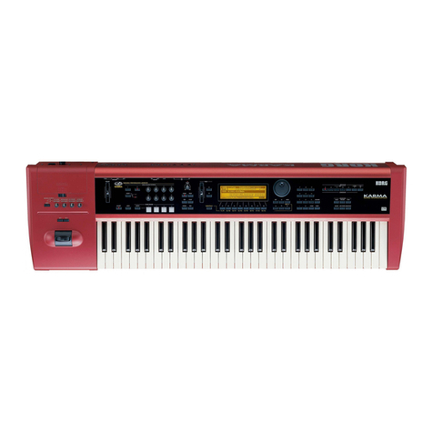
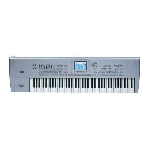
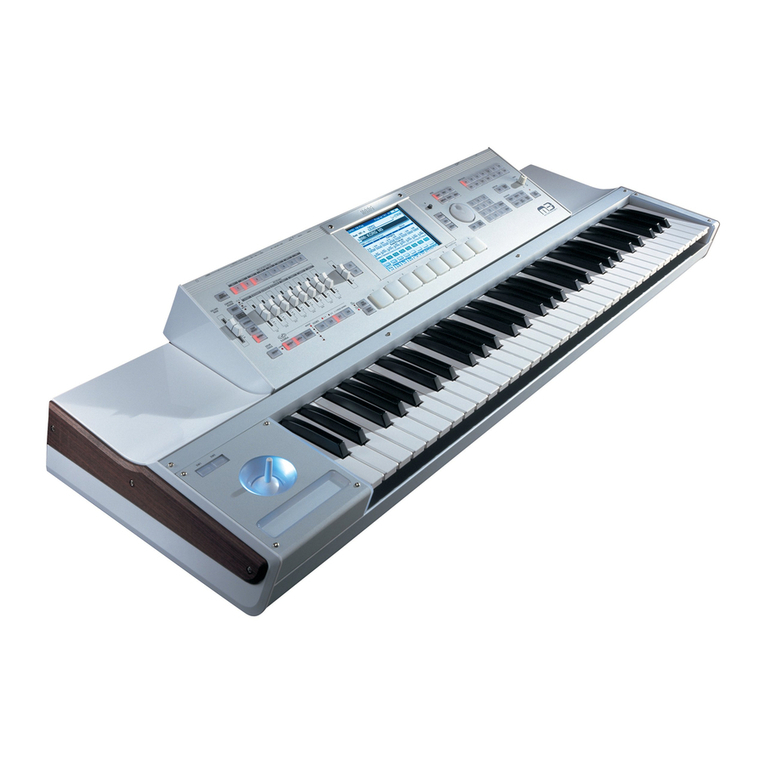
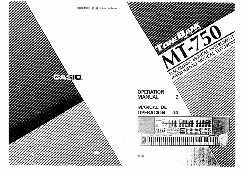
Korg M1R User manual


Congratulations and thank you
for
purchasing the Korg Music Work Station MIR. Please read this manual
carefully
to
obtain optimum performance and help assure long term reliability.
PRECAUTIONS
ENVIRONMENT
Avoid
using
this
unit
in
environments
where
it
will be
exposed
to the
following
conditions
:
*Direct
sunlight
*
High
temperature
or
humidity
*
Dust
or
sand
*Excessive
vibration
POWER
SUPPLY
Use
this
unit
only
with
the
rated
AC
voltage.
If
you
intend
to use this
unit
in
areas
where
the
voltage
is
different
from
the
rated
AC
voltage,
consult
your
KORG
dealer
about
a
suitable
voltage
transformer
unit.
INTERFERENCE
WITH
OTHER
APPLIANCES
This
unit uses
microprocessor
circuitry
that
may
cause
interference
with
nearby
radio
or
TV
receivers
.
If
problems
occur,
use
at
a
greater
distance
from
the
radio
or
TV.
HANDLE
GENTLY
Although
this
unit is
designed
and
constructed
to
KORG's
high
standards,
the
use
of
excessive
force
may
cause
damage
to its
keys
and
knobs.
CLEANING
Use
only
a
soft,
dry
cloth
to
clean
the
exterior
of
this
unit.
Never
use
benzene,
volatile
cleaners
or
solvents,
polish
or
cleaning
compounds.
WARRANTY
PROCEDURE
The
product
warranty
ensures
that
all
repairs
conducted
within
one
year
from
the
day
of
purchase
are
free
of
charge,
but
if
the
necessary
steps
were
not
taken
in
filling
out
the
warranty
card
at
the
time
of
purchase,
portions
or
all
of
the
warranty
may
be
invalid.
Make
certain
to fill
out
the
warranty
card
completely
at the
store
where
the
instrument
was
purchased
and
keep
the
card
in a
safe
place.
OWNER'S
MANUAL
The
MlRis
a
sophisticated
digital
music
device
with
many
functions.
Therefore,
we
suggest
that
you
keep
this
manual
handy
at all
times,
for
reference
.
1

CONTENTS
Precautions.............................................................................................................
...
....................................
.1
Front/Rear Panels..........................................................................................................................................4
BASIC OPERATION..............................................................................................................................................6
Structure
of
the
MIR
AI Synthesis.........................
..
.............................................................................
..
...............
..
....
..
..........
...
.....6
Keys &
controls
........................................................................................................................
..
..
..........
..
.
..
.9
Setting Up ...................................................................................................................................................
11
How to Play Combinations...........................................................
...
....
..
.........
..
..........................................
11
How to Play Programs .
......
.................
...
....................................................................................................
12
How to Operate the Sequencer ..................................................................................................................14
How to Record with the Sequencer...........................................................................................................
14
Sound Making Process ..............................................................................................................................
15
Internal Memory Allocation.......................................................................................................................16
Memory Card Format ................................................................................................................................ 16
MODES & FUNCTIONS......................................................................................................................................17
How to Read the Display Page Chart
1
-PROGRAM
MODE..............................................................................................................................
18
Editing in the Program Mode ...............................................................................................................18
2 - EDIT PROGRAM MODE....................................................................................................................20
Structure
of
the M1
R's
Program Parameters......................................................................................
20
Functions in the Edit Program Mode...................................................................................................
21
Editing in the Edit Program Mode
..
....................................
...
.....................
..
.
..
....................................22
3 - EFFECT PARAMETERS .............................
....
...
............
..
...
....
.....
...
...................................................36
Effect Placement...................................................................................................................................
.36
Names
of
the Effect Types and an Outline of their Parameters..........................................................40
Reverb....
..
.................
..
.................................................
..
.............
..
....................................................40
Early Reflection..............................................................................................................................
41
Delay................................................................................................................................................ 42
Chorus..............................................................................................................................................43
Flanger...............................
..
.............
..
....................
..
...
......................................
..
............................ 44
Phase Shift....................................................................................................................................... 45
Tremolo ..........
..
.......................
...
..
..............................................................
...
..
....
..
..........
..
..
..
......
....
46
Equalizer .....
..
.............
..
..
...
.............................................................................................................. 47
Overdrive......................................................................................................................................... 48
Exciter
..
...
.........
..
...........................................
..
..
.
..
.......
......
................
...
..
....
..
......................
..
.........
..
49
Ensemble ......................................................................................................................................... 49
Rotary Speaker.........
...
......................
...
................................
...
..
..
..........
..
........................................ 50
Combination Type Effects.........................................
..
...
................................................................50
Effect Parameters Default Values Chart ......................................
..
.
..
.............................
...
..
................
56
4 - COMBINATION MODE
..
..
..
..
............
...
.........
..
..............................
..
................................................
....
58
Editing in the Combination Mode........................................................................................................58
5 - EDIT COMBINATION MODE
Combination Types
61
Common Functions
of
Each Combination Type .................................................................................62
Single Type Functions ........................
....
.
..
..........................
...
........
..
.
..
.................
..
....
..
...
.
...
..
..........
..
..
65
Layer Type Functions .................................................................
..
....
..
.....................
....
..........
...
.......
...
. 66
2

Split Type Functions ..........................................................................
..
.......................
..
.
..
.........
..
.......
..
68
Velocity Switch Type Functions................:.....................................
'.
...........:.....................:..............:
..
70
Multi Type Functions.......................
...
........
..
...
...
........
..
..........................
..
........................................
...
72
6 - SEQUENCER MODE.........
..
.................................................
..
....
..
..
...............................................
..
... 79
Structure
of
Songs ................................................................................................................................ 79
Structure
of
Patterns ............................................................................................................................ 80
Editing Sequencer Data ........................................................................................................................80
Functions of Sequencer Mode..........................................................................
..
........
..
...
..
...................
81
Play .......................................................................
..
.........................................................................82
Starting Play from Midway Point
of
Song .
..
.................................................................................
.82
Real Time Recording ......................................................................................................................
83
Punch In Recording .
..
.....................................................................................................................
83
Multi Channel Recording................................................................................................................
85
Step Recording................................................................................................................................ 88
Song Initialize.......................................................................................
..
........................................
91
Track Copy......................................................................................................................................
93
Track Bounce..................................................................................................................................
93
Track Erase......................
...
..
......
...
...............................................
......
......
..
...
..
....
..
.......................... 94
Put/Copy Pattern............................................................................................................................. 94
Measure Copy .
..
...
..........
..
.......................................................................................................
..
......
95
Measure Insert................................................................................................................................. 96
Measure Delete 96
Measure Erase.............
..
...
................
..
...................
..
.....
..
.......
..
....
..
....
..
............................
...
.......
..
..
..
97
Quantize ......................................................................................................................................... 98
Pattern Real Time Recording ......................................................
..
.
..
.
..
......
..
...................................99
Pattern Step Recording
...
..
.............................................................................................................100
Get Pattern...........................................
..
..........
....
.........
..
...............................................................
101
Pattern Copy.............................................................
..
...............................................
..
.................. 102
Pattern Bounce......
..
...................................................................................................................... 102
Editing Event ......................................................
..
..
..................................
..
..
...
.....
..
...................... 103
7 - GLOBAL MODE ..............................................................
..
.....................
..
..............
..
..
..
..................
..
110
Functions in the Global Mode............................................................................................................110
MIDI SYSTEM EXCLUSIVE............................................................................................................................122
ERROR MESSAGES..........................................................................................................................................132
SPECIFICATIONS AND MISCELLANEOUS INFORMATION.................................................................134
Specifications...................................................................................................................................... 134
MIDI Implementation ..................................................................................
..
..........
..
........................ 135
3

FRONT/REAR
PANELS
[FRONT
PANEL[
(See
the KEYS
AND
CONTROLS
section,
p.9 for
explanations
on
each
key
and
control.)
(1) PROG/SEQ DATA slot
CD
®
r:---------
r
--
..
___
_
1PROG/SEQ
DATA:
1PCM
DATA
:
:
n..::n:
:
::
.....
:
I
.I
I
I
I
,,
''LJ
'---------J
~
- - - - J
®
-----~--
- 1
!~AOS~ER
.voL~M
.. !
I I
I•
.I
I I
:. . . . :
I 0
10
:
L---------
iPHONEs-
,
l@
'-----
--
@
®
r-----------------------------------------------------------,
I I
:
COMBI
100
8aseSin9le
Pro9ra~
I:
: I 01 E. 8
.;
:i:=.::;.
Le•.
..ie
l ='39
I - I
~-I
_______
_!
_______I_______
_!
___
----~-
_____
_!
______
_!
____
--~-
_____
1_
j
.--
-
----------
----
------------
---------
--------
1 A B C D E F G
:~
L------
~~~~~~~
[";AGE--_-
-;--PAGE-~
lc;;;!_~J
@ ®
~-oOWN
_f
_;
_
---u;-1
:c:=J~:
..._
______________
...
®
(6) MIDI indicator
Only cards that are stored or will be stored with Program (sound
color) and sequencer data should be inserted here. Remember that
the PCM (Multisound) data card should be inserted in the PCM
data slot on the front panel.
This lights
up
when MIDI signals are being received.
(7) CONTRAST dial
This controls the brightness
of
the display on the front panel.
Turning the dial clockwise darkens the characters on the display
and turning it counterclockwise lightens them.
(2) PCM DATA slot
Only cards that are stored with PCM (Multisound) data should be
inserted here. Do not insert the Program/sequence data cards here.
(3) MASTER VOLUME
(4) PHONES jack
For connection
of
a stereo headphone set. The outputs
of
OUTPUT
l/L
and 2/R can be monitored.
(5) Display
[REAR
-PANEL]
-ACY
D
(8) Cursor keys (A-H)
(9)
PAGE+
I -keys
(10) UP (.&)/DOWN
(T)
keys
(11) VALUE Dial
(12) INT key/CARD key
KORli
MODEL
M1A
SERIAL
NO
.
[
AC
1go,y
5
s~;,sgJ~;
13
wJ
NO
GUA fWITEEISAPPL
IE
OW!iENUSED
OOTSIOEJAPA~
4
(1) MIDI THRU jack
(2) MIDI OUT
jack
(3) MIDI IN
jack
CD
® ®
THRU
OUT
IN
'--MIDI----'

®
(j)
r
-,,---
--,
1MIDll
1CONTRAST1
I
It
I
I
11
• • • I
I
l/•o·•
r O
11
•
·:
L
__
J I 0 0 I
L-~--·-
.J
VALUE
...
0
..
.
. .
' .
' .
. .
.
r-------
------,
l I
NT
CARD
:
I
<==J
c::=2'
~
==-=-====::.---------~
1 COMBI
EDIT
COMBI :
:<==J
c=J:
I I
I
PROG
EDIT
PROG
I
:<==Jc=]:
:
SEQ
GLOBAL :
l<==J
~:
t_
____________
.J
--'----
_:e~~-,
I
START/STOP
: I
REC
I
:<==]::~:
L.;
__
--~'---
---'
~--------------,
: Q 5 I
i<==J
c=J:
: l 6 :
:<==]
c=J:
: 2 7 :
1<==J
c=]:
I J 8 :
i<==J
c=J:
: 4 9 :
:<==J
c=J:
f
~~~~R~.:-~:~-~~-;o~c=:
:<==J:~c=::):
·---
__
11
___
--~
MIR
IMUSIC WORKSTATION
[I]
I
POWER
OWN
--~--·
KORG
(13) Mode Select keys
COMB!=
COMBINATION Mode
EDIT COMB! = EDIT COMBINATION Mode
PROG = PROGRAM Mode
EDIT PROG
=EDIT
PROGRAM Mode
SEQ =SEQUENCER Mode
GLOBAL= GLOBAL Mode
(14) START/STOP keys
(15) REC key
(16) Numeric keypad (0-9)
© @
2 4 3
2/R
l/L
ASS.
PEDAL/SW
L___
OUTPUT
----'
(4) ASS. PEDAL/SW jacks (1,2)
For connection
of
pedal and footswitches. Assigninglarameters
to be controlled
by
the switches is done
in
the GLOB L Mode,
Function F 2-1.
(5) OUTPUT jacks (1/L, 2/R, 3, 4)
These are the
Ml
R's
voice output jacks. The assignment
of
voices to the desired jacks
is
done in each
of
the Effect
Parameters sections
of
the EDIT PROGRAM, EDIT
COMBINATION and SEQUENCER Modes.
5
(17) COMPARE key
(18) BANK HOLD key

BASIC
OPERATION
!STRUCTURE
OF
THE
MIRI
4-Channel Digital Audio Signal (internal routing) 4-Channel Audio Output
SYNTHESIZER A -EFFECT SECTION
SECTION B -Dual system stereo effects
Maximum
of
8 Programs c -
(sound colors), 16 voices D -
t
8-Channel Sequencer Play Data
SEQUENCER SECTION
8tracks
k1
SYNTHESIS
SYSTEM
J
1/L
..___
-
2/RE-
3 -
4 -
The
AI
(Advanced
integrated)
synthesis
system
of
the
MIR
makes
it
possible
to
combine
all various sound types
-- from
conventional
synthesizer
sounds
to
sampled
sounds
and
drum
sounds.
For
sampled
sounds, the
large-capa
city
PCM
data
memory
of
16
bit
x 2
mega-words,
far
greater
than
that
of
conventional
samplers,
has
been
utilized,
and
a
carefully
selected
group
of
Multisounds
(a
sound
whose
original
wave
shape has
been
multi-sampled
1) has
been
installed.
For
its
synthesizer
sounds,
not
only
the D.W.G.S. waveforms2,
which
are
produced
by
a
process
much
the
same
as
that
of
an
analog
synthesizer,
but
also
aperiodic
or
irregu
lar
waveforms
created
by
extraction
of
harmonically
unrelated
frequency
components
3
are
part
of
the
M
lR
's
structure
.As a result,
creation
of
new
and unique
sounds
beyond
the
existing
limitations
of
the
conventional
synthesizer
is possible.
Processing
any
of
the
programs
or
individual
sounds
with
the
use
of
VDFs
(Variable
Digital
Filter)
and VDAs
(Variable
Digital
Amplifier)
is,
of
course,
possible
.
Moreover,
different
effects
can
be
assi
gned
to specific
programs
in a
configuration
of
2 systems
and
2
channels
through
theMlR's
MDE
(Multi Digital Effect) feature
when
playing
Multisounds.
With
the use
of
these
functions,
total
control
over
all aspects
of
sound
creation,
including
effects,
is
possible.
1 Multi Sampling
The
harmonic
structure
and
overtones
present
in high
pitched
sounds
usually
differs
from
that
of
low
pitched
sounds,
even
in
the
same
musical
instrument.
Multi
Sampling
is
a
method
to
recreate
those
characteristics
by
sampling
an
instrument
repeatedly
over
a
range
of
many
octaves.
2 D.W.G.S. (Digital Waveform Generator System) Waveform Data
The
instrument
sound
is
reproduced
by the
following
process
:
Computer
analysis
determines
the frequency
components
of
the
sampled
instrument
sound
and
reproduces
them
by
creating
a harmonic
table
for them as is
done
in
additive
synthesis.
3 Extraction
of
Harmonically Unrelated Frequency Components
Sep
arates
the
aperiodic
and ha
rmonically
unre
lat
ed
components
characteristic
of
such
sounds
as
objects
bein
g
hit
or
scraped
from the
sampled
wave
shapes.
6

MUL
TISOUND---
-
--
(Original Sound Waveforms)
The oscillator (OSC) is selected from
the Multisound (00 to 99).
Multisounds can be selected from
the
PCM
card.
See EDIT PROGRAM mode, F0-2
for more details.
An
original program can be created
by performing various processes to the
Multisound.
The VDF (Variable Digital Filter)
controls the sound color.
The VDA (Variable Digital
Amplifier) controls the sound
volume.
These processes are done in the
EDITPROGRAM Mode.
INSTRUMENT
SETTINGS
DRUM
KIT
Assigns drum sounds to
i.he
keys.
Example:
BASS DRUM 1
2 SNARE 1
3
HITOM
4 CLOSED HI HAT
5 OPENHIHAT
6 CRASH CYMBAL 1
7 RIDE CYMBAL 1
8 HANDCLAPS
9 HI CONGA
(MUTED)
10
LOBONGO
11
BASS DRUM 2
12
SNARE2
13 MIDTOM
14
LOTOM
15
CLOSEDHIHAT
16
PICCOLO SNARE 1
17
PICCOLO SNARE 2
18
CRASH CYMBAL 2
19
RIDECYMBAL 2
20
HI CONGA (OPEN)
21 LOCONGA(MUTED)
22
HIBONGO
Instrument settings, including pan,
are edited in the GLOBAL Mode.
PROGRAM
MODE-
-
--
---
--
-
--------,
The work "Program" as referred to in this manual is synonymous with "sound
color"
or
"preset voice" in other synthesizers.
Program numbers available for selection are from 00 to 99. (Selection from
only 00 to 49 is possible when large sequence allocation is selected.)
Single
osc
Double
OSC1
Drum Kit
ORMS
·.
, .
, .
, .
, .
,'
.
' .
, .
, .
.
.
.
.
.
.
.
.
.
.
.
.
.
.
.
.
.
TheEDIT PROGRAM Mode
can
be
used for making
settings up to this point.
OUTPUT
@[E!]
®
©~
©
Choose from 4 different
instrument settings.
The pan setting
of
the
Drum Kit, which is set
in the GLOBAL Mode,
has priority.
VDF
.
.
.
.
.
COMBINATION
MODE----
•The word "Combination" as referred to
in this manual means two
or
more
programs that have been grouped
together for simultaneous play.
Combination numbers available for selection are from 00 to 99. (Selection
from only 00 to 49 is possible when large sequence allocation is selected.)
Program changes received via MIDI in the COMBINATION Mode change the
Combination.
Layer Split
Timbre
Settings for Layer
or
Split can be made in
the EDIT COMBINATION Mode.
Separate MIDI channels can be assigned
to each Program (or timbre) when Multi
is chosen. In this way, one
MIR
Music
Work station can, with the aid
of
an
external sequencer, output eight different
sound colors at the same time.
When using
theMlR's
built-in sequencer,
'Programs can
be
assigned to each track
of
the sequencer without having to create a
Combination.
7
When Layer
or
Split are used:
OUTPUT
@[E!]
®
©~
©
When Multi is used:
OUTPUT
~
©~
®
©~
@

SEQUENCER MODE (Song 0 to
9)---
When using external sound sources:
1tr
)'>
2tr
JJ
3tr
C>
4tr
MIDI OUT
5tr
6tr w
7tr
J
Bir
®
[§2]
®
©
@
~
Programs are assigned to each song.
The pan setting can be madefor each track.
The effect setting can
be
made for each song.
1 song can
be
made up
of
8 tracks
OUTPUT
Tracks
c~
be
created by combining pattems(OO to 99).
PAN~~~~~~~~~~~~~
CD
-~--
A
A:B
B
+@
..,,,..@ @
®~®+®
© © ©
@ @ @
c D
@ @
® ® ®
•©
..r
....
© ©
@~@•@
L @
<D
The volume difference between the two outputs can be
changed overa range
of
ratios from 1:9 -9:
1.
® Sends signals to C and D
at
the same volume.
8
--EFFECT
El,
E2------------,
When set to parallel operation:
A
EFFECT
B
EFFECT
2
c
...
t
IT
...
D
...
t ...
When set to serial operation:
A
B
c
D
EFFECT
EFFECT
2
1/L
2/R
3
4
1/L
2/R
3
4
Effect
1
and
Effect2
are
set
in
the
effects
pages
of
each mode.

IKEYS
AND
CONTROLS!
Numeric Keypad
,-6----
---
--
---
-
-5-
~
!
c::=::J
~
!
: l 6 i
i
c::=::J
~
i
: 2 7 :
i
c::=::J
~
!
: 3 8 :
i
c::=::J
~
i
: 4 9 :
!c::=::J
~
!
__
__
_ _ ,
__
__
___
________
J
C
OMPARE
BANK
HotD
c::=::J
~
BANK
HOLD
Key
0 5
c::=::J
C:=J
l 6
c::=::J
C:=J
2 7
c::=::J
C:=J
3 8
c::=::J
C:=J
4 9
c::=::J
C:=J
CO
MPARE
BANK HOLD
c::=::J
~
COMPARE Key
0 5
c::=::J
~
l 6
c::=::J
~
2 7
c::=::J
~
3 8
c::=::J
~
4 9
c::=::J
~
CO
MPAR
E BANK HOLD
~~
MODE
SELECT
Keys
INT
CARD
c::=::J
~
r-co
Msl
---
-e
o,r
COMB1-;
ic::=::J
~
:
:
PRO
G
ED
IT PROG i
ic::=::J
~!
: SEQ G
LOBA
L :
~c_
______
_
!__
~
j
r--
sea
----,
STA
RT/STOP
RE
C
c::=::J
~
INT Key
and
CARD Key
IN
T C
ARD
[
(
_
~::
:
.
·:
_
1
j
_
~::::::
)
]
CO
MBI
ED
IT COMBI
c::=::J
c=:>
PR
OG
ED
IT
PR
OG
c::=::J
c=:>
SEQ GLOBAL
c::=::J
c=:>
r--
sea--,
S
TART/
S
TOP
REC
c::=::J
~
These
are
used to:
Select
the
Combination
in
the
COMBINATIO
N
Mode.
*
Select
functions
in
other
modes.
The
tens
digit
of
the
program
or
combination
number
can
be
"held
"
while
changing
program
or
combination
numbers
by using the
BA
NK
HOLD
ke
y.
For
example
, p
ressi
ng
the
BANK
HOLD
key
once
aft
er
numb
er 21 has
been
selected
will allow you to
select
other
numb
ers
in
the
20
-29
range
simply
by
pressing
the
number
that
corresponds
to the
ones
digit
of
the
desired
number
; in
our
example
,
pressing
3 will
change
the
number
to 23,
pressing
to 7
will
change
it
to
27,
and
so on.
The
BANK
HOLD
key
will be lit when the
Bank
Hold
function
is on.
To
turn
the
function off,
pres
s the
BANK
HOLD
key
once
more
.
This
key
temporarily
returns
the
Program
or
Combination
which
is
being
edited
in the
EDIT
COMBINATION
or
EDIT
PROGRAM
Mode
to
the
setting
that
existed
before
editing
.
Pressing
the
COMPARE
key
again
restore
s
the
edited
parameter
values.
However,
data
edited
before
pres
sing the
COMPARE
key
will be lost
if
editing
of
other
parameter
s
or
s
witching
to
other
modes
is
don
e.
The
COMPAR
E
key
also
functions
as
a
MIDI
panic
button;
in
other
words,
when a s
tuck
note
occurs
in
sequencer
play
or
control
through
MIDI
IN,
one
press
of
the
COMP
ARE
key
will
turn
the
note
off. (This
can
be
used
in
any
of
the
modes.)
When
the
COMPARE
key
is
lit
, the
original
sound
can
be
heard
and
it
s
parameters
are
dis
played
;
unlit
,
the
COMPARE
key
indicates
that
the
edited
sound
is
display
ed
.
The
selected
mode will
be
lit.
Press
the
INT
key when u
sing
the
Combination
/
Program
/S
ong
data
of
the
internal
memory
of
the
MIR
.
Press
the
CARD
key to
access
the
ext
erna
l
(card)
data.
9

NOTE: The waveforms of the
PCM
(Multisound) card are selected
in
the Oscillator Assign function of the EDIT
PROGRAM Mode and the Drum Kit functions of the GLOBAL Mode.
In
these exceptions, the INT Key and
CARD Key are not used.
NOTE: Make certain
to
insert the card straight and firmly into the correct slot.
Cursor
Keys
and
VALUE Dial
A 8
CD
EFG
HQ)
Parameter
values can be
changed
by
pressing
the
cursor
key
below
the
parameter
to be
edited
on the
display,
then by
adjusting
the
VALUE
dial.
Cursor
keys used to access
different
function
and
parameters
will
be
indicated
in
squares
( D )
throughout
the
rest
of
this manual.
cc=
=1c=
IC
=~Ii==
=rr
_-_-
_I
l
=~=
n
===
JT_-
_=
Ir
UP/DOWN Keys
DOWN
I I
UP
c=--,
c=)
These
are
used
when
finely
adjusting
the
values
of
parameters
that
are
difficult
to set
only by
using
the
VALUE
dial
or
when
making
fine and
detailed
alterations
in the
sound.
Pressing
UP
increases
the
value by I and
pressing
DOWN
decreases
the value
by
1.
*
Concerning
the
UP/DOWN
keys:
The
cursor
will
appear
under
the
Combination/Program
number
at
the
bottom
left
of
the
screen
when
pressing
the
COMBI
key
or
PROG
key
of
the
MODE
SELECT
keys
(immediately
after
selecting
the
COMBI
or
PROG
Mode)
.
Pressing
the
UP
key
in this
condition
will
advance
the
Combination
or
Program
number
by one
and
pressing
the
DOWN
key
will
decrease
it
by
one
.
*
The
VALUE
dial
cannot
be
used
here
to
change
the
Combination
or
Program
.
*
Pressing
any
of
the
cursor
keys
(
~
through
!HJ
)
will
move
the
cursor
to
the
performance
edit
parameters,
and
editing
can
be
done
by
using
the
UP/DOWN
keys
and
the
VALUE
dial.
To
return
the
UP/DOWN
keys
to
function
as
Program
up and
down
after
selecting
the
performance
edit
mode:
in
PROGRAM
Mode,
press
the
PROG
button; in
COMBINATION
Mode, press the
COMBI
button.
In
each
case,
the
cursor
will
return
to its
position
under
the
Combination
or
Program
number
and the
UP/DOWN
keys
can
be
used
again
to
increment
and
decrement
the
Combination
or
Program
number.
PAGE+/-
Keys
PAGE
+
PAGE
C=-=1 I )
START/STOP Key
INT
CARD
c===i C==>
COMBJ
f DIT COMBI
c===i C==>
PROG
EDIT
PROG
c===i C==>
SEQ GLOBAL
c===i C==>
r-
SEQ
------,
START/STOP
REC
[~_-
I:::
-~::)J
REC Key
INT
CARD
c===i C==>
CO
MBI
EDIT
COMBI
c===i C==>
PROG
EDIT
PROG
c===i C==>
SEQ GLOBAL
c===i C==>
.--
sea
--,
START/STOP
RE
C
[~---~J
Each
function
of
the
MIR
is
organized
in display
pages.
These
keys
allow you to
access
succeeding
and
preceding
display
pages by using the
PAGE
+ and
PAGE
-
keys,
respectively.
·
This
key
is
used
to
start
or to stop the
sequencer.
If
you press this
key
in any
mode
other
than
the
SEQUENCER
Mode, the
MIR
will
automatically
move
to
the
SEQUENCER
Mode
and
play
will start.
When
the
sequencer
is
playing,
the
first
beat
of
the
measure
is
indicated
on
the
key by a flashing red light;
other
beats
are
indicated
by a
flashing
green light.
This
key
is
used
to
begin
recording
when in the SEQ mode.
The
lamp
remains
lit
while the
sequencer
is
running.
I
10

Is
E
TTIN
G--uP
I
I. First, check that the power switch on the
front
panel of the
MIR
is
OFF. Check that the power switches of all
connected equipment (amplifiers, mixers, etc.) are also OFF. For protection
of
all audio equipment (and your ears!)
tum
the volume
of
all equipment completely down.
2.
Insert the power cord (which is included as standard equipment) into the power plug on the rear panel, then insert the
other end
of
the cord into the proper power outlet.
3. Turn the
MIR's
power switch ON.
4.
Tum
the power switches
of
all connected equipment ON.
Then
turn
the
MIR's
volume
and
that
of
the
other
equipment
up
gradually
to the
desired
volume.
The
MIR
will
not
sound,
however,
if
the
MIDI
channels
of
the
MIR
and
the
connected
external
MIDI
devices
are not
matched.
Please
see
the
section
"How to
Match
MIDI
Channels"
below.
*
fAmplifier, mixer,
etc]
11 1
MIDI
IN
1/L
2/R
3 4
MIR
0
MIDI
OUT
All
note
data
from
C-I
to
G9
(note
numbers
O-I27)
are
received
through
MIDI
IN.
(Some
of
the
Programs
may
not
sound
when
played
in
higher
ranges.)
/How
to
M~tchuMIDTChannels
I
(1)
Press
GLOBAL
of
the
Mode
Select
keys.
(2)
Press
"5" on the
numeric
keypad.
(3)
Make
sure
that
the
cursor
is at the
"CH=
"
display.
If
it is not, press
cursor
key
ffi]
.
(4)
Adjust
the
VALUE
dial until
the
desired
MIDI
channel
is
displayed.
*
For
situations
in
which
MIDI
data
is
being
received
over
different
channels,
settings
are
made
using
Multi
functions
the
COMBINATION
Mode
or
SEQUENCER
Mode.
IHOW
TO
PLAY
COMBINATIONS
(SOUND
COLOR
GROUPS)
I
INT
CARO
c=J
[===:>
:--cOMsl--
--eo1T
COM81
-:
i~
c=:>:
:
Fl<OG
EDIT
PROG
i
ic=:J
C===>!
:
SEQ
GLOSAL :
ic=J
C===>i
-T.:_:_.:_:_:_-~.-$.;
1~~"Key
r--sea-,
STARTISTOP
REC
c:::::::::J
[===:>
,-----
Numeric
Keypad
f-6-------
--
-
----5-~
!c=J~i
i l 6 i
!c=J
~!
i 2 7 :
:c=J
~
i
! 3 8 :
ic=J~:
: 4 9 i
l~--~j
COMPARE
BANK HOLD
c=J~
(1)
Press
the
COMBI
key
of
the
mode
select
keys; this
puts
the
MIR
in the
COMBINATION
Mode.
(2)
Select
the
number
of
the
Combination
(00 to 99)
which
you
want
to
play
by using
the
numeric
keypad
.
(3)
Play
the
keyboard
to
hear
the
sound
of
the
combination
selected
in
step
#2.
These
are typical
displays
from the
COMBINATION
mode:
11

Example#!
Combination number
2 Combination name
3 Parameter
of
currently selected cursor position
COMB!
101
Piano+TrP
L~~er
1 Pro9raM
*IQ0
R.Piano
L70
102
TrUMPet
L82
4 Number, name and volume level
of
the program being
used
A 8 C D E F G H
I?\
__..__.__.__.____.__.__.-0
5
Cursorkeys
Example#2
COMB!
-104
MultiCoMbi
IQ1
102
103 Ip5 106
Tl=E.
Bass
109
IIO
I12
A 8 C D E F C H
--------
6
Program
name
of
cursor
position
7
Number
of
the
Program
being used
Example
1
shows
a
display
when
a
Layer
Combination
is
selected.
The
Program
number,
Program
name
and
volume
level
are
indicated
when
the
Combination
is a
Layer
or
Split.
When
replacing
the
Program
of
Layer
1
(Program
number
IOO,
directly
above
cursor
key
[Al
)
with
another
Program,
press
cursor
key
[Al
then
adjust
the
VALUE
dial.
The
display
pages
are
often
laid
out
such
that
one
parameter
description
will
occupy
the
space
over
several
cursor
keys.
The
cursor
keys
just
under
that
parameter
(and
up to the
cursor
key
of
the
next
parameter)
can be
used
to
access
the
parameter.
The
sound
volume
of
Layer
1 can be
changed
by
pressing
cursor
key
[!2]
then
adjusting
the
VALUE
dial
(maximum
= 99,
minimum
=00).
Press
cursor
key
00]
when
you
want
to
replace
the
Program
of
layer
2.
Press
cursor
key
[HJ
when
changing
the
volume
of
layer
2.
Example
2
shows
a
display
when
a
multi
Combination
is
selected.
As in the
first
example,
the
Program
number
shown
directly
above
cursor
key
[gJ
(Program
number
106)
can
be
changed
by
pressing
cursor
key
[g)
then
by
adjusting
the
VALUE
dial.
IHOW
TO
PLAY
PROGRAMS
(ONE
SOUND
COLOR)
]
(1) Press the PROG key
of
the mode select keys; this puts the
Ml
in the PROGRAM Mode.
(2) Select the number
of
the Program (00 to 99) which you want to play by using the numeric keypad or UP/DOWN
keys.
(3) Play the keyboard to hear the sound
of
the Program selected in step #2.
Here
is a
typical
display
from
the
PROGRAM
mode:
INT
CARD
C:=J
c:::::=:J
:--COMsl-
--
-E01T
COMBr-;
!c=::J
c:::::=:Ji
:
PROG
EDIT
PROG
:
!~~!
: SEQ GLOBAL :
iC:=J
~:
--r.:_:__:_:_:_:_-~~~~-.;~
r---sea--,
START/STOP
REC
C:=J~
,_-ModeSelect Key
:--o---
-----
------
5-~
!c=::J
~!
: 1 6 :
!c=::J
~!
! 2 7 :
:c=::J
~:
: 3 8 :
ic=::J
~i
: 4 9 :
:c=::J
~
:
L-------------------
-l
COMPARE
BANK HOLD
c=::J
~
EXAMPLE
~
Cf
.--------------P
~
PROG
100
Universe
OSC
Balance
0+05
F+03
L-02
K+10
U-08
R+01
R-01
E+03
A 8 C D E F G H
--------
1
Program
2
Internal
program
number
3Program
name
4
Parameter
The
display
shown
when
selecting
the
PROGRAM
Mode
is
like
the one above.
While
this
display
is
shown,
the
pressing
of
any
single
cursor
key
and
adjusting
of
the
VALUE
dial will
change
the
value
of
the
parameter,
which
is
indicated
above
the
selected
cursor
key.
In
this way
Programs
may be
easily
edited
without
having
to
enter
the
EDIT
PROGRAM
Mode.
This
is
particularly
convenient
for
making
on-the-spot
sound
changes
during
live
performance.
12

*
The
functions
of
the
parameters
are
as
follows
(see
pp.18
·
-19
in
the
PROGRAM
Mode
for
more
details):
0 =
OSC
Balance
(Oscillator
balance)
This
parameter
controls
the
relative
sound
volume
of
the
two
oscillators
of
programs
having
two
oscillators.
The
larger
the
value,
the
greater
the
volume
of
OSC
1
becomes.
(Range:
-10
to
+10.)
F =VDF
Cutoff
(VDF
cutoff
frequency)
This
parameter
controls
the
frequency
point
from
which
all
lower
frequencies
are
pa
s
sed
and
all
higher
ones
are
cut
off
by the VDF.
The
higher
this
number
is
the
clearer
or
brighter
the
timbre
of
the
sound
becomes,
and
the
smaller
the
number
the
more
muted
or
soft
the
timbre
becomes.
(Range:
-10
to
+10
.)
L'
= VDA
Level
This
parameter
adjusts
the
level
of
the
entire
Program
by VDA.
(Range:
-10
to
+10
.)
K =KBD
Track
(Keyboard
tracking)
Used
in
conjunction
with
VDF
Cutoff,
this
parameter
sets
the
degree
to which
keyboard
pitch
aff
ects
the
amplitude
and
the
cutoff
frequency.
The
larger
the
number
set
with this
parameter,
the
wider
the
variation
in
timbre
becomes,
corresponding
to the
note
played.
(Range:
-10
to
+10
.)
V =Vel.
Sens.
(Velocity
Sensitivity)
This
parameter
sets
the
degree
to
which
key
ve
locity
affects
the
amplitude
and
the
cutoff
frequency.
The
larger
the
value
lis, the
greater
the
change
in
timbre
becomes,
corresponding
to how hard
the
keys
are struck.
(Range
:
-10
to
+10.)
A =
VDF/
A
EG
Attack
Time
(VDF
and
VDA
EG
attack
time)
This
parameter
controls
the
attack
time
of
the
program.
The
larger
the
value
is,
the
longer
the
attack
time
becomes.
(Range: -
10
to
+10.)
R =
VDF/
A
EG
Release
Time
(VDF
and
VDA
EG
release
time)
This
parameter
controls
the
release
time
of
the program.
The
larger
the
number
is,
the
longer
the
release
time
becomes.
(Range
:
-10
to
+10.)
E =
Effect
Balance
This
parameter
controls
the
volume
ba
lance
of
the
effect
and
direct
sounds.
The
larger
the
number
is,
the
greater
the
ratio
of
effect
sound
to
direct
sound
becomes.
(Range:
-10
to +10.)
NOTE: The values of the parameters here will return to their original settings when
you
select other programs.
When moving to other modes, the parameter value (and, hence, the sound) remains at its stored
or
edited
setting. When moving back to the PROGRAM Mode, the display value will be reset
to
zero, but the actual
value remains unchanged.
13

IHOW
TO
OPERATE
THE
SEQUENCER
I
Specially
prepared
sequencer
demonstration
data
has
been
loaded
into the
internal
memory
of
the :MlR
at
the
factory
.
Before
recording
your
own
data,
let's
listen
to the
demonstration
data.
1.
Press
the SEQ
key
of
the mode
select
keys; this puts the
Ml
in the
SEQUENCER
Mode.
2.
Press
cursor
key
ill].
SONG0
Ml
DEMO
31%Free
R/P
Son90
Trl
M001
J=120 *100
U99
c•~l
A B C D E F G H
3.
The
value
above
the
cursor
can
be
changed
by
adjusting
the VALUE dial.
Select
song
number
0 by
4iiiiiiiit
&iiiiiii
4iiiiiiiit
&iiiiiii
4iiiiiiiit
4iiiiiiiit
&iiiiiii
4iiiiiiiit
INT
CARD
c=::::J c=:>
r-co..;s1-
--
-E01T
COM81-:
!c=::::J
c=:>i
: PROG EDIT PROG :
!c=::::J c=:>j
: SEQ
GtOBAL
:
i~
c=:>
i
T~-~~~~-
s;,;~~~ey
r-
SEQ
--,
START/STOP
REC
c=::::J
c=:>
INT
CARD
c=::::J c=:>
COMBI EDIT COMBI
c=::::J c=:>
PROG
EDIT
PROG
c=::::J c=:>
SEQ GLOBAL
c=::::J c=:>
r-
seo
----,
STARTISTOP
REC
[~_-1:::-~::?J
turning
the
VALUE
dial
counterclockwise
as far as
it will go.
4.
The
sequence
can
be
played
by
pressing
the
START/STOP
key.
5.
Play
can
be
stopped
by
pressing
the
START/STOP
key
again.
IHOW
TO
RECORD
WITH
THE
SEQUENCER!
CARO
c=::::J
c=:>
:--coMsl-
---ED1i
COM81-:
!c=::::J
c=:>
i
] PROG EDIT PROG :
ic=::::J
c=:>
j
: SEQ GLOBAL :
:
~
c=:>
i
--r.:..:..:..:.:_-M~~-s~l~~~.v
r-SEO----,
START/STOP
REC
c=::::J
c=:>
SONG9
New
5on9
31%Free
R/P
Son99
Tri
M001
J=120 *100 U99
C•~l
A B C D E F G H
4iiiiiiiit
&iiiiiii
4iiiiiiiit
4iiiiiiiit
4iiiiiiiit4iiiiiiiit
4iiiiiiiit
4iiiiiiiit
CARD
c=::::J
c=:>
COMBI
EDIT
COMBI
c=::::J
c=:>
PROG EDIT PROG
c=::::J
c=:>
SEQ GLOBAL
c=::::J
c=:>
r-
seo
----,
START/STOP
REC
[~_-_-~}
Now
that
you've
heard
the
demo
sequence,
follow
these
steps
to
record
some
sequenced
music
of
your
own.
1.
Press
the
SEQ
key
of
the mode
select
keys; this
puts
the
MIR
in the
SEQUENCER
Mode.
2.
Press
cursor
key
~
.
3.
Select
the song to be
recorded
by
adjusting
the
VALUE
dial.
Select
number
9 here.
4
Select
the
track
to be
recorded
by
pressing
the
cursor
key
[g,
then
adjusting
the
VALUE
dial.
Select
[l]
for now.
5
Make
certain
that
the
MIDI
transmit
channel
of
the
external
keyboard
matches
the
MIDI
channel
of
the track.
6
Press
the
cursor
key
IEJ
,then
select
the
program
to be
used by
adjusting
the
VALUE
dial.
Select
any
Program
you
wish.
7
Press
the REC key.
8
Press
the
START/STOP
key. Begin
playing
after
a
lead-in
of
2 measures.
Recording
starts
at
this point.
9
After
finishing
recording,
press
the ST
ART/STOP
key
once more to stop
recording.
10
Playback
can
be
executed
by
pressing
the
START/STOP
key.
14

[SOUNIJ
--
MAK
I
NG
PROCESS
I
Here
is a
summary
of
the M1
R's
sound
making
process.
1.
Select the sound
to
be edited in the
PROGRAM
Mode.
c==i
c=)
;--cOMsl-
--
-ED1i
COMB
1
-:
:
c==i
c=)
i
: PROG
EDIT
PROG i
!
~c=)
j
:
SEO
GLOM.L :
:
C=:J
c=)
i
--~-
M".;.J~~~;~~
"
Key
r--
SEO---,
START/ST
OP
REC
c==i
c=)
j--------------
-----i
, See the MODES AND '
: FUNCTIONS chapter, :
section
#1
PROGRAM ;
; MODE (p. 18) :
L-- -- ----- -
-------
--l
...
2.
Create the sound color in
the EDIT PROGRAM mode
and write it to memory.
IN
T
CA
RD
c==i~
:-
-coMsl-
---
E01T
COMBI:
!
c=:::J
c=)
i
: PROG EDIT PROG :
i
c=:::J
~
!
: SEQ GLOBAL :
~
~
--
~
j
r-SEO---,
STARTISTO?
REC
c==i~
r--
-------
--
-
------
---,
1 See the MODES AND '
I
' FUNCTIONS chapter,
section #2 EDIT
: PROGRAM MODE(p.20):
L----
-----
----
- -
-----
_J
15
...
...
3. Create the Combination
by combining the Programs
created in step #2 in the
EDIT COMBINATION
Mode.
INT
CA
RD
c==i~
:--COMsl
---
-ED1TCO
M
81-
1
!
c==i~:
: PROG EDIT PROG i
[
c=:J
~
[
: SEQ GLOBAL :
:
c==i
~
:
-----
--
--
----------
-
-"
r-
SEO
---,
START/STOP
REC
c==i~
See the MODES AND
FUNCTIONS chapter,
section #5 EDIT COMBI-
' NATION MODE (p
..
61) I
I - - - - - - - - - - - - - - - - - - - - -
_1
3. Record a song using the
Programs created in step #2
in the SEQUENCER Mode.
I
NT
C
AR
O
c==i
c=)
:--cOMsl
--
-
-eo1T
COM81-:
!c==i
c=)
i
: PR
OO
EDJT
PROG
:
i
c=:J
c=)
j
: SEQ GLOBAL :
i
~
--
-~
j
r--
SEO
---,
STAR
T
/STOP
REC
c==i
c=)
I - - - - - - - - - - - - - - - - - - - - -
-,
See the MODES AND :
' FUNCTIONS chapter, :_·
section #6 SEQUENCER
I
MODE(p
.79)
'------------------
----

!INTERNAL
MEMORY
ALLOCATION
!
Large
Sequence
Allocation
Combination 10 Banks
Memory = 50 100 Patterns
Program Memory =
50
(a total
of
less
(memory numbers
150
than 7700 steps)
-
199
cannot
be
selected)
Large Program Combination Memory 10
Ban1cs
Allocation (set = 100 100Patterns
at the factory Program
Memory=
100 (a total
of
prior to to less than
shipment) 4400 steps)
There
are
two
different
kinds
of
internal
memory
allocation
(the way
available
memory
is
used) in the
MIR.
*
Changing
the
memory
allocation
setting
is
done
in
the
GLOBAL
Mode,
F6 - 4
(p.117)
NOTE:
Be
careful when switching the memory allocation setting, since much of your precious data
cou
ld
be
irretrievably lost.
!MEMOR
Y
CARD
FORMAT!
Program Card 100 Combinations
100 Programs
1Global Parameter
SequencerCard
Program/Sequence
50
Combinations
Card
10 Banks
100 Patterns
(a total
of
less than
7700 steps)
10 Banks
100 Patterns
(a total
of
less than
4200 steps)
The
M 1
has
three
kind
s
of
memory formats.
*
*
PCM
cards
are
not
included
in
this
c
la
ssification
.
Use
KORG
MCR-03
RAM
cards.
Two
RAM
car
ds
are
necce
sary
in
order
to
save
all
the
internal
memory
data.
Ca
rds
for
the
M 1R
and
the
M 1
can
be
used
int
e
rchangably
.
Writing
in and
reading
out
of
data
from
card
s
can
be
done
by using the
following
fun
ct
ions:
Read Out Write In
All
Programs,
Combinations,
;
sequence
data
All Programs, Combinations Global Mode F8 - 1 Global Mode F9 - 1
All sequence data
1 Combination COMBIMode EDIT COMBI Mode F9 - 1
1 Program
PROGMode·
EDIT PROG Mode F9 - 1
1 song SEQ Mode F9 - 2 - - - - -
1pattern SEQ Mode
F9
- 3 -----
16

MODES AND
FUNCTIONS
HOW
TO
READ
THE
DISPLAY
PAGE
CHART
F0-2
OS
Cl
(Oscillator
1)
------------------------------------
CD
~
Multisound Multisound OSC 1Multisound
Select Name (original waveform)
Selection (when the
OSC mode is set to
SINGLE or DOUBLE)
Drum Kit Drum Kit
1-
Drum Kit Selection
Drum
Kit4
(when the OSC mode
is set to DRUMS)
@]
sOscillator
0-99
Volume
of
Level Oscillator 1
00
LOctave
Octave setting
of
Oscillator 1
16'
1octave down
.---
8' standard pitch
4'
~
1octave up
~
!...
~
T T
CD
F 0-2
OSCl
(Oscillator
1)
: Indicates that this is the
second page
of
function 0 and that the function is called
Oscillator 1.
@ The cursor key to be used to access the parameter.
@ The abbreviation
of
the parameter that is shown on the
display.
© Name
of
the parameter.
® The range
of
values and settings
of
the parameter.
® Brief explanation
of
the parameter's function.
17

1
--
PROGRAM
MODE
In
this
mode
Programs
(sound
colors
or
preset
voices)
can
be
selected
and
played.
Programs
are
selected
by
the
numeric
keypad
(0-9),
UP/DOWN
keys,
footswitch
(PROG/COMBI,
UP/DOWN)
or
MIDI
program
change.
* A
Program
within
the
internal
memory
is
selected
when
INT
is
selected
and
a
Program
within
the
card
is
selected
when
CARD
is
selected.
*
Before
selecting
a
Program
by
footswitch
or
MIDI,
the
appropriate
function
has
to
be
set
for
operation
in
the
GLOBAL
Mode.
NOTE: Panpot settings are given a default value of A:B = 5:5 in all Programs except the Drum Kit. (Signals are
not output to Outputs 3 and 4.)
EDITING IN THE PROGRAM MODE
PROG
IOO
Universe
DSC
Balance
0+05 F+03 L-02
K+10
U-08
~+01
R-01
E+03
A B C D E F C H
................
~
............
~o
OSC Balance
-10
-+10 Controls the volume balance
of
OSC 1and OSC 2
of
the Programs when
setto DOUBLE.
[fil F
VDFCutoff
-10-
+10 Controls the cutofffrequency
of
VDF 1and VDF 2 (changes the tonal
quality
of
the sound).
@]
L
VDALevel
-10-
+10 Controls the level (volume)
of
OSC 1 and OSC 2.
@]
K Keyboard Track -
10-
+10 Controls the sensitivity
at
which changes in sound color and volume are
affected by the part
of
the keyboard played.
[ID
v Velocity
-10-
+10 Controls the sensitivity
at
which changes in sound color and volume are
Sensitivity affected by how hard the keyboard
is
played.
[E}A
Attack Time
-10-
+10 Controls theattack time
of
VDFs
1,
2 and
VD
As
1,
2.
@)
R Release Time
-10-
+10 Controls the release time
of
VDFs
1,
2 and VDAs
1,
2.
IBJ
E EffectBalance
-10-
+10 Controls the balance
of
the direct sound and the sound
of
Effects 1 and 2.
When
ed
itin
g
parameters
in the
PROGRAM
Mode
,
corresponding
Program
parameters
in the
same
Programs
of
the
EDIT
PROGRAM
Mode
are
assigned
the
same values.
*
Edited
Programs
should
be
written
to
memory
in
the
EDIT
PROGRAM
Mode
.
18

Program
parameters
change
as shown in the
chart
below when
selecting
positive
parameter
values("+"
settings).
The
reverse
changes
occur
when
negative
values("-"
settings) are used.
PROGRAM Mode Parameters Effect ofa positive value setting on each parameter
OSC Balance OSC 1Level The level
of
OSC I increases, while that ofOSC 2 decreases.*1
OSC
2Level
VDF
Cutoff VDF
1,
2 Cutoff Increases (or assumes a positive value).
*1
VDALevel OSC
1,
2 Level
Keyboard Track VDF
1,
2 KBD TRK Cutoff Increases in proportion to note number
of
key played.*2
EGTime
VDA
1,
2 KBD TRK Amplitude
EGTime
Even when set to a negative value, only the absolute value
Velocity OSC
1,
2 EG Level Vel Sens becomes smaller, but the sign("+"
or"-")
does not change
Sensitivity EG Time Vel Sens
VDF
1,
2 VEL SENS EG Int
EGTime
VDA 1,2 VEL SENS Amplitude Parameters with values set to
"O"
remain as
"O"
and do not
EG Time change.
Attack Time VDF
1,
2 Attack Time Increases (or assumes a positive value).
*3
VDA
1,
2 Attack Time
Release Time VDF
1,
2 Release Time Increases.
*1
Effect Balance EFFECT
1,
2 Balance
*1 Assuming that the original
value=
V, then the changed value
is
increased or decreased
by
5V.
*2 Assuming that the original
value=
V,
then the changed value increases
by
a power
of
1 + (V/10).
*3
Assuming that the original
value=
V,
then
tJie
increase or decrease of the VDF value
is
by
3V, while that of the
VDA value
is
by 5V.
19
Other manuals for M1R
2
Table of contents
Other Korg Musical Instrument manuals

Korg
Korg EASYSTART CX-3 Product information sheet

Korg
Korg Stage Vintage SV-1 User manual

Korg
Korg O1/W FD User manual

Korg
Korg SP 250 User manual

Korg
Korg KRONOS2-61 User manual

Korg
Korg SV-2 User manual

Korg
Korg X3R User manual

Korg
Korg SP-170S User manual

Korg
Korg EXB-RADIAS for M3 User manual

Korg
Korg i30 Operator's manual