Korg 770 User manual

SYNTHESIZER K0RG770
OWNER'S MANUAL
£©gias/>tz+t-i'+f- 3Jl/7770£ Congratulations'on purchasing Synthe-
sizer KORG 770. Please read this
manual carefully to ensure the unit's
fullest performance.
&*» MAJOR FEATURES
3;u^ 770 ii-3/uf 700 S'f K^TflfcKA ') £
&<.!f*I«g ^-4 2IS *#Ki-C, ¥fr 3K•
*rix z.cn&mmt-t :
s>**t l*¥-{mi>ixtz
?tit VVS, gWl-7^7
•Two Built-in Oscillators
Only the KORG 770 and MINI-KORG 700 Sin
this range of synthesizers have two built-in os-
cillators. Two tones can be obtained simulta-
neously not only having different colors but also
having different pitches. In addition, it can pro-
duce sound with colors at intervals of the major
third and perfect fifth and percussion sounds of
bells, gongs, etc. With rich nonintegrated har-
monics by using a RING MODULATOR.
•Accurate Tone Pitch
Most instruments of this type may, in some cases,
give such an image that asynthesizer is too un-
stable to produce good quality and,accurate pitch.
However, the KORG Synthesizer -ian be played
with accurate pitch as soon as? th«j pgwer swi-
tch is turned ON. So far this, essergjal require-
ment has been satisfied by onlyjK&afay models.
•External Input Jack ., ..jjj i\
An input jack is provided fpr cohn'ecjing an eleW
trie guitar, electronic 'piano, voice* of another syn-
thesizer. Variations and changes of tone Jjjplor
can therefore be obtained by passing these sounds
through the circuitry of the VCF, the ENVE-
LOPE GENERATOR and the RING MODULA-
TOR and/or combining them with PINK NOISE,
WHITE NOISE, etc.
•KORG's Unique Traveler Machanism
•TRIGGER/REMOTE Mechanism .
&HWc&£.Mfc BEFORE USE
•»*5**«"C-+<iO**»Lfc»)«*£Jn*fc ») Lfcv»*
Protect the unit from heaters, sunshine, humidity,
dust and vibrations.
Keep neon tube lamps, fluorescent tubes, trans-
formers .and electric motors away from the unit
in order to avoide noises. .
Be careful .not to gijjte it aheavy shockAor a.
... '**
drop since it is aprecise instrument.
,
-I-

^>-fet>ff-co*#ft£l<* FUNDAMENTAL MECHANISM
OF THE SYNTHESIZER
SJPc, i& Wi •*- 3>-?- r<o n$ftj&ij (= §
-1- <fc h#fc«gs ofiijic tt -> x*>> ^-
>-t -y- -r -if- (?) $i- w*nx±fs lx
Mm -Ciii-^^t'l"o
*7-~*m-f —^-W
£->>-b-«f 'f -f
v^ tS-3 Tt
Jti: rtB#j
ti-^t L-4
tl, ^-4-eii
\~r>^x%HX
Listen to a radio or television set, and you will
find that synthesizer music is generally used not
only in music programs but also as background
music for TV and as drama accompaniments. You
could say that we are surrounded by synthesized
sound.
Why are synthesizers used so often ?This is
because synthesizers are capable of imitating the
sounds of other instruments and also creating uni-
que sounds that have never been realized by any
musician. Described below .are the fundamental
components of a synthesizer,, the knowledge of which
is essential in order to use the instrument at its
best.
<*> >-fe If -f If:-<n m*Mf&> <Fundamental Components of a
Synthesizer >
vco VCF
KEYBOARD
VCO Voltage Controlled OscUlator(1gffiiElHB$6ffi&) <r>
*frr\ fi«£fl|;e.*fcVCoa<ssis.L. s.<rMM!
&
mtte ') it,
EG Envelope Generator (aifrSSSMS) <n*&X\ f«
2. *, i& ') ,i&-&%tm £a>i- a->\> Lit,
VCF Voltage Controlled Filter (WWM7 -f is, 9-)
VCA Voltage Controlled Amplifier iMJ£%m*ti%&) ^
VCA
EG
Signal Output
Signal Flow
Controlled Signal
VCO Voltage Controlled Oscillator. Depress a key, and
the VCO produces sound.
EG Envelope Generator. For controlling sound rise
time and damping characteristics.
VCF Voltage Controlled Filter. For determining tone
color.
VCA Voltage Controlled Amplifier. For determining
sound volume.
JiLk**. i/>-fe-tM-f-<sO-«#ltl*-C-r*f,XfR£
lift T-K #tlX v> h-7 -a -, 7ri-V 7=7 f-!-fi<f J: i
t, ^<nm^< <nmmmwtcom&b-tti-£-?'xm
By various combinations of the fundamental compo-
nents described about and by using the many acce-
ssories shown in the block diagram in the latter
part of this manual, an infinite variety of tone
color can be created.
-2-

'**>vm h&^ &fr(D%fo FRONT PANEL AND KNOBS
©LFO SPEED ©PITCH-FINE
©PITCH ©PITCH- COARSE
©OCTAVE ©MODE
©MODE ©PILOT LAMP
©MIXER ©POWER SWITCH &VOLUME
VCF ENVELOPE
GENERATOR VCO
MODULATOR
©HEADPHONE JACK
©PORTAMENTO
©TRAVELER
©BRIGHT
©L.P.
©LFO
©H.P.
©ATTACK TIME
©SINGING LEVEL
©SUSTAIN TIME
©RANGE
©TRIGGER/REMOTE
©MODE
©BEND -DELAY
©BEND- SPEED
©VIBRATO-DEPTH
©VIBRATO-SPEED

JgiBE<9La*fc HOW TO
MAKE CONNECTIONS
T>7°
AMPLIFIER
y^y—^fJUFK-l
TRAVELER
PEDAL
-^>7X3> ha—y-
MOUTH CONTROLLER
try
Sound can be colored wifh afine pianoforte, vibrato
effect, and brightness by means of ones breath.
1- y^y-PJlfm^ti> ill:
rftMT§i\
Use it when operating the TRAVELER by foot.
ELECTRIC
GUITAR COMBO ORGAN
fM-i >"?> ri-'-v-v J'lilVp-pJ-fA 1)*f. K-ttS#it* J:
<-f£fc«6l;:, T"£*/..'ftlVp-p{;:fiv>A*j£ArlTT3i.\,
Xl/3ff7/
ELECTRIC PIANO
External input jack is available up to 1voltage peak to peak.
In order to make better signal ratio set the input as near at
1voltage peak to peak as possible.
When you use lower output voltage input signal such as
microphone or electric guitar, use pre or booster amplifier.
-A—

mk<nmi¥ •im PLAYING PROCEDURE
AND METHOD
li x4-y ?• £Ait H^'B
>*£««**¥ LS -Tilt?* ^tfvfftfcifaasJil-
(Practice playing in accordance with the following.)
•Set the rotary knobs, the slide knobs and the
lever switches on the control panel as shown in
the drawing below.
•Plug the power cord into socket, connect the
synthesizer output and the amplifier using the
connecting cord provided, and turn the power
switch ON.
•Depress akey, and the instrument will emit a
sound similar to that of an electronic organ.
Then, adjust sound volume to the required level.
n'- ^m
an
."0. ~0CM
El ©
VCO 1VCO II
€3
«J1
2S'N
PORTAMENTO
@10
8
Sy'IIIK'**" KOflO
I13IS67t910
II I I I I I f
IIIIIIIII
.8 8
88
ENi/ELOPE OEHEBATOR
88
88
VCO MOD 5
§
0>-~--<IO Bf^ gj^
VltJHATO *
®VCO I
•PITCH -
OCTAVE-
MODE
i.&VtltcWh h'-vfoJAj£
fi-^lllLTT?^ rtnmsiiftiz
mt&Ms, stent ti& <&u
*
w<oo**-c£Kfi*j £1*9281, 7*
*t;
CD VCO I
•PITCH Turn the PITCH knob clockwise and
counterclockwise, depressing akey.
Turning it clockwise will make in-
crease the pitch and counterclock-
wise low reduce it.
Adjust the pitch for tuning with
other instruments.
•OCTAVE- -Turn the OCTAVE knob, depressing
akey. It has five control steps, the
tone varying by one octave for each.
With its F-scale 32 keys, two and a
half octaves combined the synthesizer
actually covers atone range equi-
valent to 92 keys, 7and ahalf oc-
taves.
•MODE Turn the MODE knob and the OC-
TAVE knob simultaneously while
playing asimple melody. You will
then learn the characteristic of
each wave form.
-5-

•mm
/\ BM3&
n_ w&m f$&{§t£ **•£ 4it -c ££s* fc ^.ffliY*
ilS+
affimm flatted* s#*&&*, a**^
tit J to ffi, f, $?£&% *wflfeAJ»
n./<;uxjg[
CHORUS
3—yX2oo*SS |pJli#l-P.ft &Lfc ft i-4-3»*
Tz?><r)\z- HSliLFOxf- K«o-^
i^T'fTi-^ii". T3-fit >4if <7)
EXT.
INPUT
x-9 7,9-
+K<
>,ffcw x > -fe-t.'f t-^ ««& Lxm
m-t &t § fc I* -Wtf S* xa>-l:L TT
$V\, (fflL, VCO I- t'7f, **
>-7i VCO MODULATOR--o K
WAVE FORMS
/\Triangle
[TSquare
ASaw-Tooth
O-Pulse
CHORUS
EXT.INPUT
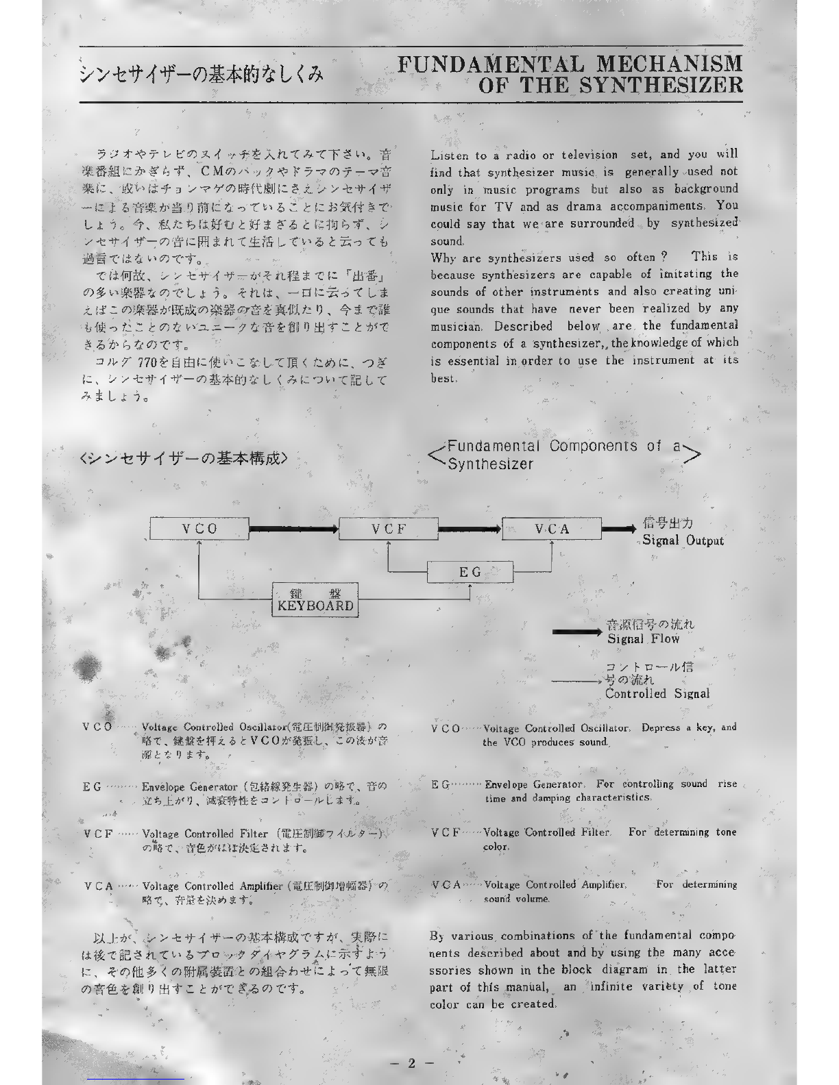
The fundamental component of
harmonics is rich and provide a
pure and clear sound.
Most appropriate for creating
sounds in the flute family or a
clear sound color similar to a
tuning fork.
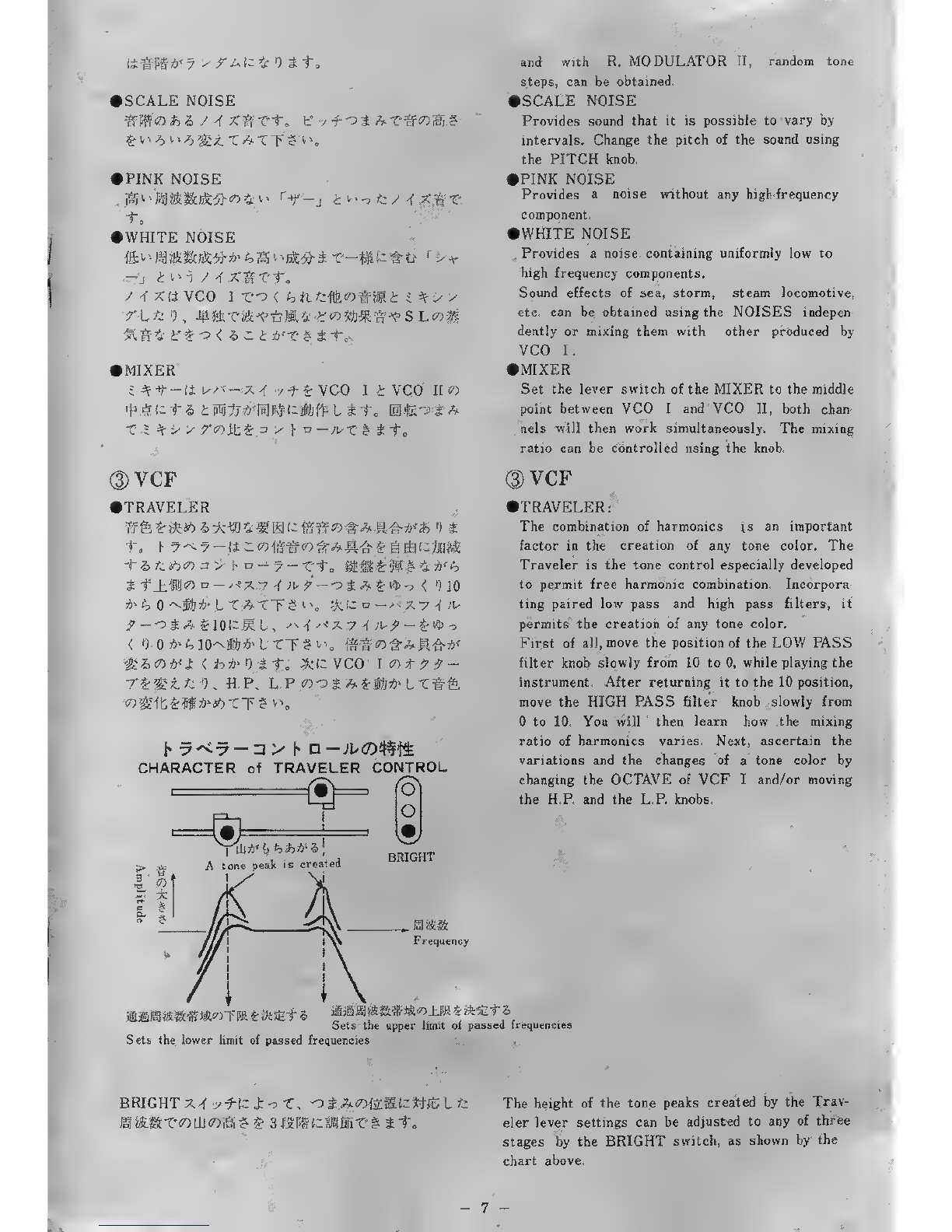
Since there are few harmonics,
the Traveler Control effective
direction is not particularly ex-
treme.
Provides closed-pipe sounds (cla-
rinet, etc.) by removing even-num-
bered harmonics.
Since this basic tone contains
many harmonics and is sufficient-
ly large, it is suitable for creat-
ing awide range of tone colors.
Its versatility can be expanded
by combining the Traveler Cont-
rol to create string, wind, picked
string and human voice effects,
plus many others.
Higher harmonic elements abound
in this waveform, making use of
the Traveler Control highly effec-
tive, especially for creating reed
sounds or all new synthetic tone
colors.
The effect produced when two in-
struments are played simultane-
ously can be obtained. Using the
LFO speed knob adjust the beat
to obtain the difference in pitch
of two tones. Accordion and simi-
lar sounds can then be easily
produced.
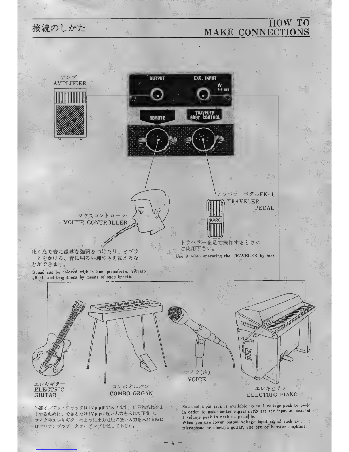
Use this position when an electric
guitar, an electric piano or an-
other synthesizer, etc. is connect-
ed to the external input jack at
the rear.
Dvco n
M**-*> a4»/ +£VCO 1*>(, vco ik-^x.
-CTS^. StSg^ffti VCO n«§4'Lit. %
\z. t'/fp-x (COARSE) oiAfcBIL-CT* £»
e-yf-«ortJli;fc;£ <4*99-~r^i]'<-L fta
fiMHSH±-7T 4>(FINEJoi^-CfToTT^^. ,
>RING MODULATOR I»II
i) ^tfi W--7-IJVC0 ItVCO IKOigf-fc
2o(7) m%i&*)wmxn&*<± #<ant l j i- ^
x
VCO 1«t;;-7ojAtVCO II«f7-fo
>?*r* v-?- iii=gfPtt. ixm+tttu n
2) vco n
IChange the position of the MIXER switch from
VCO Ito VCO II and depress akey. The
sound of VCO II will then be produced. Next,
turn the PITCH COARSE knob, and the synthe-
sizer will cover awide pitch range of 4octaves.
Make fine adjustment with the FINE knob.
IRING MODULATOR Iand II
Device for combining electrically the sounds of
VCO Iand VCO II. Particularly in relation to
two frequencies the variations and changes in
tone color can be demonstrated using the OCTAVE
knob of VCO Iand the PITCH knob of VCO II.
Using R. MODULATOR 1,continuous tone steps,

SCALE NOISE
PINK NOISE
-to
WHITE NOISE
/-f X'(i VCO IT'-o <&nfejfetfHHi i;^fy>
&#Sf if £o<&.1 ltfX' % i t„
MIXER
=^t-li^<-x^ -yf-^VCO It VCO IIO
VCF
<n is &*£• J9W:M
?—o $A %<$>-> <*) io
\,\ friz n—><X7 <f ^
%tc VCO 1<r> t79-
CHARACTER of TRAVELER CONTROL
(8\
TRAVELER
iP6*tfeW*'*SF*RSK;
to F7-<7 —(i-^f&il5
'UCAW^y hD—-7 —
iflflJWD-^xv^i-
*fc 0-~jfttf»lT^TT£
?--o$A£10lzmi, <*
<') O^lO^-tfr^lTT
'$lh<r>-h<Z. <*>*• ») it.
-rzmiK'K H.P. L.P
?)S^«l^tT?^
«o
and with R. MODULATOR II, random tone
steps, can be obtained.
•SCALE NOISE
Provides sound that it is possible to vary by
intervals. Change the pitch of the sound using
the PITCH knob.
•PINK NOISE
Provides anoise without any high-frequency
component.
•WHITE NOISE
Provides anoise containing uniformly low to
high frequency components.
Sound effects of sea, storm, steam locomotive,
etc. can be obtained using the NOISES indepen-
dently or mixing them with other produced by
VCO I.
•MIXER
Set the lever switch of the MIXER to the middle
point between VCO Iand VCO II, both chan-
nels will then work simultaneously. The mixing
ratio can be controlled using the knob.
(DVCF
•TRAVELER:
The combination of harmonics is an important
factor in the creation of any tone color. The
Traveler is the tone control especially developed
to permit free harmonic combination. Incorpora-
ting paired low pass and high pass filters, it
permits the creation of any tone color.
First of all, move the position of the LOW PASS
filter knob slowly from 10 to 0, while playing the
instrument. After returning it to the 10 position,
move the HIGH PASS filter knob slowly from
to 10. You will 'then learn how the mixing
ratio of harmonics varies. Next, ascertain the
variations and the changes of a tone color by
changing the OCTAVE of VCF Iand/or moving
the H.P. and the L.P. knobs.
>
3
a
|lill*' <>*>***&!
Atone peak is created BRIGHT
Frequency
iimm-<s.mmco±m *• feetz
Sets the upper limit of passed frequencies
Sets the lower limit of passed frequencies
mmma&^ai^TiK &ft^t z.
BRIGHT X-f /tic J: of, o£A<ofitit{;:*frSLfc
-7
The height of the tone peaks created by the Trav-
eler lever settings can be adjusted to any of three
stages by the BRIGHT switch, as shown by the
chart above.

*h*> <&«J3R$ u^tn?**. *£<fta» l
TlffS'-jfafe-tirRKfl'ai-^'f 5>?'£-£-*)-£ Tft
BRIGHT
LFO
Low Frequency Oscillator (jBK&^&S&^S) <0»&
Bftfi-H-fT? «*'LFO X-f ••/ f-T-i"o. Y7-<7-
o*AH <7)*T-Eta .LFX-f y-f £1ULT
h. v-<7--5 £*£f=-C-ft*> LfcB$wS»J£ £-fc*
fltf, Sft«Cimt«»*«:fll*4w tU4:«) It.
LFO 2(i ft * t$1 *£<LHtofk C«M3 $.?,\-y
^f-WfaStv^^^SEifc 1), 7^ KLF
Omxt'-F. VCOlnt^^-T-fJii^j
EXPAND
Fi JfJ'.!-X-f /-fT-"t„ (Envelope Generator CO
(D ENVELOPE GENERATOR
•ATTACK TIME
ick*:< &o^-To
•SINGING LEVEL
.-?<') 8*• S> ^ft *' UT?", «p*tt -5
^\Z'P&.i tt 9*1"o 79<•/ 994J*r>
£
Aifl
SUSTAIN TIME
'), xi00li«<«») *+.
When the Traveler is used as apre-set, one
touch will permit the player to find atone color
spontaneously, once he is familiar with the ope-
ration of the two levers. When the Traveler is
used dynamically, afine back and forth movem-
ent will create atremolo. Awider left-right
sweep will give rise to acurved tone which,
when properly timed to the keyboard action,
can create awah or amuting effect.
•BRIGHT
For adding traveler resonance effect. The posi-
tion lprovides stronger resonance effect than
the position 2. Explore the variations and the
changes of tone color by setting the knobs at
various positions.
•LFO
Low Frequency Oscillator. For adding repeat,
howling and other effects in order to change tone.
Set the BRIGHT switch at position 1hold the
upper and the lower TRAVELER knobs together
with the left hand, and, playing the key board,
move them right and left between the 4and 6
positions. The above effects can automatically
be produced using the LFO switch. Set both
TRAVELER knobs at position 5, set the LFO
switch at position 1, and turn to adjust the upper
left LFO knob to the cycle obtained by handling
the TRAVELER knobs manually. Asimilar effect
will then be produced automatically. The LFO 2
provides the same effect as is obtained by irioving
the knob over a large distance. Test the effect,
changing the position of the TRAVELER, the
BRIGHT, the LFO SPEED, the VCO IOCTA-
VE, etc. in various ways.
•EXPAND
Switch for connecting the ENVELOPE GENE-
RATOR to the VCF. (Refer to ^ENVELOPE
GENERATOR".)
®ENVELOPE GENERATOR
•ATTACK TIME
Change the position of the ATTACK TIME knob
slowly from to 8while playing the instrument,
and the rise time will gradually be lengthened.
•SINGING LEVEL
While playing the instrument, move the position
of the SINGING LEVEL slowly from 8to 0,
the sustaining power of sound will then be gra-
dually lessened. Try this out in. various ways
in combination with the ATTACK TIME.
•SUSTAIN TIME
For varying the sound duration after removing a
finger from a key. Sound disappears quickly at
XI position, sustain time is short at X10 and
longer at X100.
-8

MODE
iut:
s>%>ru-< n- t<7>ffl.teb-& x-hui&t & £
tb<X-h±1\
9-X-TA >(3-fev r"f &t # it±£&<?>4 XT-i V?
>MODE
Set the knob at the PERCUSSION position, and
sound will disappear quickly. Sound duration can
be controlled by changing the combination ratio
of SUSTAIN TIME and SINGING LEVEL.
When setting the knob at the SUSTAIN posi-
tion, select aSUSTAIN TIME setting. Set the
knob at the HOLD position, and sound will last
for as long as you want.
PERCUSSION 79~t 99<UX"&ir>h
Varied with the knob set at the ATTACK TIME position.
I
I
*-£fl't
Key press
Varied with the knob set at the SUSTAIN TIME position.
"" .1
Determined by the SINGING LEVEL.
Key release Time
Has no relation with the timing of Key-Off. The thick line indicates the envelope.
SUSTAIN
a<r>
=k
2-«
79-v 994i.X-&hb
Varied with the knob set at the ATTACK TIME position.
Key press
*tXT 4>9-i utHihb
\Varied with the knob set at the SUSTAIN TIME position.
1
>/*:> 9" l- ^<>i--C-ik£&
mmml—mmJL_ Determined by the
SINGING LEVEL.
Key release Time
HOLD 99-iX, X-kh b
dwith the knob set at the ATTACK TIME position.
Key press
I
v>%> '/v<ivx-:
<k£ h
IDetermined by the SINGING LEVEL.
Key release Time
>-fe -f i-f -r-o <feits flgjrg v>§(73 g&$ its 2> "i
J5 $T-T *'bi')IUTXl-L TATT ?*g
j*? Never before provided in electronic organs, the
ENVELOPE GENERATOR constitutes one of
the most important characteristics of synthesi-
zer. It provides awide range of fundamentals
of the sounds produced by the synthesizer, which
can be demonstrated by making trials.

>RANGE
tt< tfc9«*< i»*H Lit,
GRANGE
For lengthening or shortening the volume varying
time of the sound made by the ATTACK TIME,
the SINGING LEVEL, the SUSTAIN TIME
and/or the MODE.
TRIGGER/REMOTE
}• 'J if-/ f*— rX-4 /+£*-!-*/ btht
|^*g £'jf.lt fifi >-<p-7°xi?-u-^- **$& h§
J-t, iHJfJiwWrtf^xa -x T'j>liffl L* t„ LFO
13 -fe /ht&£s's
*>•>' a—,xo*>W. J: -) ©')
h"- h^*£-3fta^£*f-r-#sto tXf^f
UX'f •yf-£$j#'LT^*^ia^£*t*>#>TT£
X3^o-7-f) |-J:i)r/<n--/f3>|.
TRIGGER/REMOTE
Set the TRIGGER/REMOTE switch at the KEY
position and play the instrument. The ENVE-
LOPE GENERATOR will then work. It is usually
played at this position.
Set it the LFO position, and arepeat effect
such as is produced by abanjo or axylophone
can be obtained. Asertain the variation and the
change of the effect by moving the switch. Set
it at the REMOTE position, and the envelope
can be controlled by an external signal (e.g. a
mouth controller on aseparate sale).
EXPAND
it, -t-^XTi-l&b-z. 5R60ny I- a-jv '*%i\,m
t|S] t.-K ?-y aV\~ -te ••/ rLift LTT ?y\ W-t>\
VCFfflScoj.^-x^y KX4 •yf-K&g LTTS<".
3-v -<n --? :
Ji- *v-?-<r>7 9-, 9-9 -{ t-%. %
l:tii, ]£*3±')60i;-?-v>^l3^i) *t„ f-t'
r?-f U^/fSll^U r7-<y-60±T60O
£<*<£ £fc ,4TJ8 £!"]»#*- OA'^51 t*ft ** LTT
#*%, ;w»^gl(itjl:oai:(i %h7-<i7-
60_hT^>**£ S^fiST'Eia, i^^'y^-f
••/ *£NOR. (NORMAL) CLtt. fife, ITSI t
[S]B$|3 r7^7—«0Sia^o &A£10*' fe 5lzW)fr
Ik# tmta&*li REV. (REVERSE) Ti# 6tl
ft.
x.*7.'<v Y'UJL>-^a —-f-J z.^.v —9—"CO <
o^^S60^tt,*-V"-C h7-<7-W'tX-f •/
fb'icii'T'iit. i>-<n-7"xi *w—
-£(3j:oT5ij*li^:$ <**>•) it.
•EXPAND
First of all reset all the knobs in the positions
shown in the drawing of the control panel on
page 5paying attention to the EXPAND switches
of the VCF part.
Set the ATTACK TIME knob of the ENVELOPE
GENERATOR at the 8position, and sound will
rise slowly. Then, set the BRIGHT switch at
position 1, set both the upper and the lower
knobs in the same position and simultaneously
depress akey and move the position of the knobs
from to 5. To produce this effect automatical-
ly, set both the upper and the lower knobs at
the 5 position and set the EXPAND switches
at the NOR. (normal) position. In addition the
effect obtained by depressing akey and moving
the position of the lapped knobs of the TRAVE-
LER from 10 to 5can be produced by setting
the EXPAND switches at the REV. (reverse)
position. The EXPAND switches are for moving
the TRAVELER in accordance with the sound
volume variation curve produced by the ENVE-
LOPE GENERATOR.
The effect can be varied to alarge extent by
changing the combination of the ENVELOPE
GENERATOR, the TRAVELER and the BRI-
GHT in various ways.
10

i)VCO MODULATOR
>VIBRATO
«£!*!#«- fry- M**>:f 9it. T««f-f i'
-f .^v'->3 vli^TSSmL!*"^ <It tr7?- M**
*»•) St. £fUifl£*fr-tffc^#t::a&*a*A ,J4
t*>t\ Xh°-Ks 7""7°X<7)-?i^£I]t'C!
Depress akey
DELAY
VIBRATO
'
YlWlA/
2) VCO MODULATOR
VIBRATO
The middle point of the switch is the OFF posi-
tion of the VIBRATO. VIBRATO effect can be
obtained by depressing akey in the same way
as with an electronic organ, by setting the knob
at the upper NORMAL position.
It will be obtained sotne time after depressing
the key with the knob set at the lower DELAY
position.
The VCO MODULATOR applies this effect to
music melody. Turn the SPEED and the
DEPTH knobs in various ways to understand
the relationship of actual effects.
Time
t-77- r*'» <*/!• 4S*">S.
Vibrato begins to sound strongly.
BEND !
7.4 ;1-codp'kl£'<> KOFF cofeS T't.
±ffilj\*->-d'3 vliJT«&L(ffc <Ltlt?^-
r^**T*« o»Til 't&v=y ay\t l*99-?±
&ni to
74 i-*f, xf-F(0^iAj||]hU ^h^co^h
')#£.£ <5S*^TT?^o
o4A£lttia±>l, **>£&*£ J: <SJSl£_hT\
DPORTAMENTO
v<n ^cofti s£jUggl i;oiH«tt„ -749*
K(FIXED) l±g-w&?f+SI$IW**#1irufi <4-
ErHcirab*^ Htffflt^it, *fcn a>ro
-/i--^/'i/3>!:t4i:, ±.<r>-o£7>-$:mi?tz.
\tz%x.htl£t„
bI- J: 9^pwfMf1" &
£*{
(2) LFO SPEED
•VCO Iso^-KoUJ3-7Xl:-fe7 H, L
FO Xh1-Ko JA^liU ih') «f-? SML
TT?^'o
•VCF>?)LFOx-f -yf-g 1Zli2C-b-/ rUL
LTTS^.
•x>•.<- 7° i-'x *Is— 9-CO I- IJtf—/'j^— r
7,4 7fHFO!:-fev rULFOxf-KoS
A£SI Lf,-v >K') >,'*> S> a—,4" i* co «fc ?
4') f- !-?ft«<7>xe- K^ftftTTS^.
HEADPHONES
|ffe*o -t ••/ h£^*.•& b#(7) t^;-i: rfi'ffl nfe
£
it it.
•BEND
The middle point of the switch is the OFF po-
sition.
Tone lowers by one octave some time after de-
pressing akey with the knob set at the upper \
position and rises by one octave at the lower /
position.
Ascertain the variation of the effect by turning
the DELAY and the SPEED knobs.
^When moving more than two knobs, turn one of
them first and then, after hearing the effect turn
the other.
®PORTAMENTO
For continuously connecting the pitch of one
sound on the key board to another produced next
to it. The sound with avery long transference
time produced with the knob set at the FIXED
position can be used as aspecial sound effect.
Set the knob at the CONTROL position, and
sound transference time is variable.
©LFO SPEED
•Increase or decrease vibrato speed by setting
the MODE knob of the VCO Iat the CHORUS
position and turning the LFO SPEED knob.
•Adjust the TRAVELER effect by setting the
LFO switch at the 1or 2position and turning
the LFO SPEED knob.
•Determine the speed of the repeat effect pro-
duced by amandolin or abanjo by setting the
TRIGGER/REMOTE switch of the ENVELOPE
GENERATOR at the LFO position and turning
the LFO SPEED knob.
®HEADPHONES
Ajack for connecting aheadphone is provided.
Plug in headphones and they can be used for
monitoring sound when changing the tone color
setting positions not only when practicing but
also in concert.
11 -

^7^/(t/7A BLOCK DIAGRAM
Key Board
-4-
1_
<
o
Om
Trigger Detector
~7
I
I
i
1r— i
a
=A
a. V
O-^
o
3=s
r*
-1
re
1
-J
<
o
o
Mi
n-X
re V
•< -V
<n:
si
sii
r* 1
O1
-7-
so V
P. V
oViJ
I
£I
I* 1
Z
2. v
s-^
OH
3$
p. $
o
1
7
1
1
<: n;
H
mi
o1
Ofp
pr •H»
uS5
o
"1 «
T3 ^
os_
-1 r
WVf
y
re V
3V
O
i
_i
Ow
Mixer
I
*
2- 5
«
Ji
S1^
-a
ff >>
-?. a-
r*
I
Si
oS§
3i:4
la 3
Volume
^
nU
i>j
S3 U
to V
o
r*
re a
i
I
V
u
1
Jr.
6
3
>'•
"FT
3
<
o^**
•a W
»$
3*
r*
O
1
Xs
tn \i
=r *.
$
V)
Wsj
-X
?
*1 1
-r« I
Headphones
u
Amplitude Modulator
ra
oi
*/a
si
(A -\
3V
V,
i1
<
o
H
SO
>
r
M
SO
i
S»
1l#
£3 *Oi
3.:.. Will
ofa <^S
oin
oo
3e
m3
"1 a.
O«)
C/5 7a
s3
B>

'W SPECIFICATIONS
•&• £F-Cx-7—;W32S6 (6*??-7MZJ
#(-«t »)!feWWl::92«)
•VCO I(SiSI)
If -y *
*??-? 2' ,4\ 8' ,16' .32', 64'
*-k/\, n_, /k n.
3—7*, x7X^-t'l" 4>-?•; F
•VCO II(#«II)
t* -y *3—X-, 77-f>
*-K/I
'J >7*7*3.1' —9—2
X-7—,/U/>f X. h'>?/-fX
* 7 4M4X
•VCF(^fe)
X*X/*>K L.P, H.P
L F O
•x>'<n-7'-^x*U'-*-(iM-)
\s >>X0.5, XI, X10
K
W'^T'-f V^-f AXI, X10, X100
M#-/•;*-* *-, LFO, U*- r
b'^-K f7"x, xif-F.f-f Ht--/7-K
./—wHf/?—F
•* <n te
LFXt'-F
tf)U9S>t 9<!>., 7<?XF, 3>Fa—;u
$*If -
*S*<f -y *ttff*«#Va. -A
/<<f "J r•7>~7
~5KQ i±i^6Vp-p Max.
•vy K*—> •S***y ^
Aft-f >h"-r>X 10KQ
'J*-r •a*??-
•«S/>8*«2> AC100V, 50/60Hz
15W
•»tt/M ffJ560'%.X^5?195"«nX^T340'%., 9kg
•Pit Sfl» «fca-K
-5»r7X=J >FD—7—,
•KEY BOARD 32 Keys F-C Scale 2K Octaves
(Octave switch makes 92 keys)
•VCO I
PITCH
OCTAVE 2', 4', 8', 16', 32', 64'
mode /\ n_ an_
CHORUS, EXT.INPUT
•VCO II
PITCH COARSE, FINE
MODE /I
RING MODULATOR 1
RING MODULATOR 2
SCALE NOISE, PINK NOISE
WHITE NOIE
•VCF
TRAVELER HIGH PASS FILTER, LOW
PASS FILTER
EXPAND L.P, H.P
BRIGHT
LFO
•ENVELOPE GENERATOR
ATTACK TIME
SINGING LEVEL
RANGE X0.5, XI, X10
MODE PERCUSSION, SUSTAIN,
HOLD
SUSTAIN TIME XI, X10, X100
TRIGGER/REMOTE KEY, LFO, REMOTE
•VCO MODULATOR
BEND DELAY, SPEED
BEND UP, BEND DOWN
VIBRATO DEPTH, SPEED
DELAY VIBRATO, NORMAL
VIBRATO
•OTHERS
LFO SPEED
PORTAMENTO TIME, FIXED, CONTROL
MIXER
POWER SWITCH &VOLUME
PILOT LAMP
OUTPUT JACK Output Impedance
0~5KQ 6Volt p-p Max.
HEADPHONE JACK
EXTERNAL INPUT JACK Input Impedance
10KQ
REMOTE CONNECTER
TRAVELER PEDAL CONNECTER
•POWER SUPPLY/CONSUMPTION
Set to local voltage 50/60 Hz.
15 Watts
•DIMENSIONS/WEIGHT 560"jUw) X195"fc(H)
X34C%.(D) 9Kgs.
•ACCESSORY Connecting Cord
•OPTION Traveler Pedal, Case, Stand
Mouth Controller

J
**± $S«Sf?SESi*«.«2-l90 =r 160 «208-788ITO
ttia 3K:£«tJiffl§Eliic-h.*5-6-i9 tI56
*#I* #S§JI|*£#LbSIS±#BTit^-l825 1=258
KEIO ELECTRONIC LABORATORY CORPORATION
Head Office: Maison Yutaka Bldg.. No, 190, Nishiohkubo/2-.Chorne, Shinjuku-ku, Tokyo, Japan
Factories: No. 19-6, Sakurajosui-5-Chome, Setagaya-ku, Tokyo, Japan
No. 1825 Ohimachi, Ashigarakamigun, Kanagawa Pref., Japan
Printed in Japan 5210 DTH 1
Other manuals for 770
2
Table of contents
Other Korg Synthesizer manuals

Korg
Korg DSS-1 User manual

Korg
Korg 01R/W User manual

Korg
Korg KPR-77 User manual

Korg
Korg MS2000 Product information sheet

Korg
Korg MONOPOLY POLYSIX MS-20 User manual

Korg
Korg X5D User manual

Korg
Korg MS-20 Kit User manual

Korg
Korg EX-800 User manual

Korg
Korg Kaosilator User manual

Korg
Korg Rythm KR-55 User manual