5^t>fUb'nxf-yfiA,ncAT
F*w
ft**4R
icat^*\
emortv^F^Wr-?*«!£.
<\'B
*
a
>
-7
v<n«ft*«tc
«*
A
v
^
tr+t
<
*-C
*
rt
*
ft
*i
•JfltCtt->Tl'«*C3rtUrd
fUjr*.
<}&•#**«£
left**.
<n
a
ic
im
j:
n
r
%»
l
r
\.'*t.
i
->
z
ta.
s
ru&ixnr
♦
.
niHMc.
wt*
y
*r-#
t
TWV£rtc
f
m#j
<
0
*
^
flltt-IIC.t
>CLJ;A.I1.
C<n*s»/mifc<r>*B<oftftnOafc'J.
lun&vta
-
■
f
t
6
M
U
M
*
C
L
VT*
*>fr*>to.<rrC
1
*fc.
—icwM-c
v-i*tc>nff
-*«#*
*
C0)C£ttfffe*flllllC*A£iJ.
/Y<0
mLA'«tU'»,
rt«6*Kirjictilt<*
tt
*
n&t
vv
^
lYiift**
■
■
*<«**cu
>CV.'**.
c/jcl-
.
tkmnmpntmr.
v#.xrt**to£Amru*
«)*.*#,
Wft
:
<
r>tf\t»
*«•;-?*
_
y
<*f-t
v>tr*
f
«f-tDf»ttlAsA\.sA<Li»»A->-*fc'J*i»
.<*/
Krfi
F^t>)
<*fc.
/•
**#>.
A-rU*&*yK
i3-7i»>r>7i
-XJ-79-
CJJl/?2A*-
•
7JI/f
V
15,000).
#>ij
(3Jt?-2*r
V*A¥*.500)&£'fc*l'W|l;:IC
■
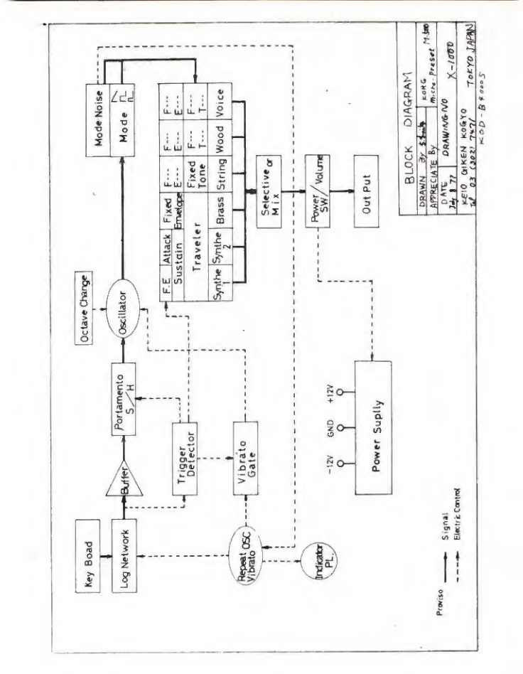
On
Synthesizers
Switch
on
the
radio
or
the
TV,
music
by
synthesizers
is
commonplace
not
only
in
music
programs
but
also
as
commercial
background
music
and
drama
theme
music.
You
could
say
that
we
are
surrounded
by
synthesized
sound.
Then,
why
has
the
synthesizer
become
so
popular?
In
a
word,
it
is
because
the
synthesizer
can
imitate
the
sounds
of
the
existing
musical
instruments
and
produce
unique
sounds
which
no
one
else
has
ever
used.
Generally,
the
synthesizer
is
a
monophonic
instrument
for
playing
melodics.
This
means
that
the
synthesizer
has
the
features
that
it
can
freely
change
tones
and
sounds,
and
continuously
change
tunes.
As
a
result
of
technological
progress,
a
polyphonic
synthesizer
capable
of
producing
chords
is
now
available,
through
at
a
very
high
price;
and
an
in¬
creasing
baricty
of
synthesizers
are
on
the
market,
(see
photo)
The
synthesizer
can
produce
sounds
by
connection
to
an
electronic
organ,
stereo
set
or
guitar
amplifier
(preferably
a
keyboard
amplifier).
And
the
effects
can
be
doubled
by
connecting
an
echo
machine,
phase
shifter
(KORG
Mr.Multi).
or
a
volume
pedal
(KORG
2
-
channel)
between
them.
(1)