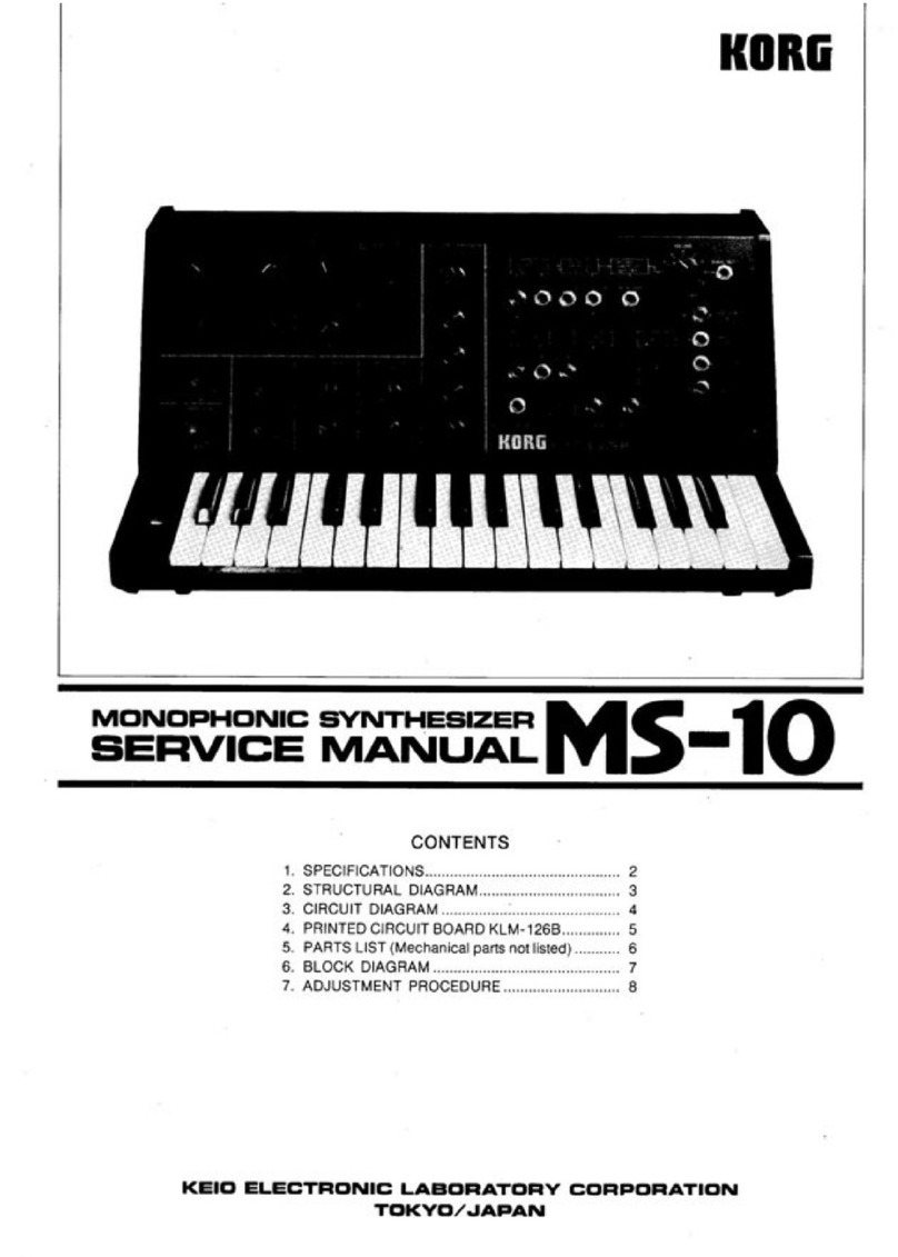
KORG MS-20
7. ADJUSTMENT PROCEDURE
7-1 Power supply check
1.Positive lippte.
Should be no more than 2mVp-p,
Set oscilloscope vertical gain at lOmV/cm end
check that power supply ripple is 2mV or less.
2. Negative ripple.
Same as positive, should be no more tharv
2mVp-pH
7-2. Pitch adjustment
1, VCO-1.
Perform adjustment with synthesizer controls at
"normal setting” (Scale =8, Waveform— fU .
Master Tune. Pitch, artd all other knobs at "0'%
See figure 1
.
a. Play C-4 (high C) on the keyboard and ad-
just the high Osernl -fixed screw until you obtain
the correct tuning as indicated by WT-10A
(connected lolheSIG OUT jack).
b. Play key C-1 and adjust the low ^semi’
fixed screw.
0
.
Repeat steps aand b as many times as
necessary until both are tuned to the correct
pitch.
d. Check the tuning of C*1, C-2, G-3, and G-4
on the WT-10A meter to make sure pitch devia-
tion is within ±2 cents for each.
e. Change the scale to 32\ 16", 8', and 4' and
check the tuning of all four Ckeys to make sure
that the pitch deviation of each Is within +10cents.
2. VCO-2.
Set the VCO-1 level at and the VCO-2 level
at '"10". Then follow the same procedure as for
VCO-1. by adjusting the high and low
semt'fixed screws.
7-3. KSDCV adjustment
Use a4-1/2 digital voltmeter to measure the K6D
CVOUT signal.
a. Measure output vottage first when you play
key C-4, then when you play key C-3. The output
voltage for C-3 should be exactly halt that for
C-4. Adjust the KBD CV high 0semi-tixed
screw as necessary so that C-3 produces half
the vottage of C-4.
b. Measure C-2 and then C-1 in the same way.
Adjust the KBD CV low 0semi-fixed screw as
necessary so that C-2 produces exactly half ihe
voltage ot C-4.
c. Repeat steps aand bas many times as
necessary until the output voltage of each of
C-1, C-2. C-3. and C-4 is exactly half that of the
next.
vHi
O®
rw
Kikl &
o
®
6
KBOCVADJ
@1
o
irCO I
O
4P
®
l4TtJT
®
C^t
O
®
P4U
®
®
%
®
H.M
®
KTtlT
>1^
Ul k
O
Uit rpta,
o
fMjO
nrtP
o
o
«irj4r
O
C-2
®
®
iTT^
®
IfcJ
o^-f>Bor^]o fT^no-o
oo o oo
imnirinT
C-3 C-4^
WT-10A
DIGITAL
VOLTMETER
Fig. 1
7-4. VCF Fc adjustment
Ck>nnect afrequency counter to the PHONES jack
(since a high output level es needed tor measure-
ment). Set VCO-1 and VCO-2 level at "0^
1.
VCHPF
Refer to the settings shown in figure 2, Set the
LPF PEAK knob at "0'\ and the HPF PEAK knob
at "10”. Then adjust the Osemi-fixed screw as
necessary so that the HPF oscillation frequency
is 500Hz.
2.
VC LPF
Set HPF PEAK at ’0”. and LPF PEAK at ”10",
Then adjust the 6semi-fixed screw in the same
way as you did for the HPF.
FREQUENCY
COUNTER


