manuals.online logo
Brands
  1. Home
  2. •
  3. Brands
  4. •
  5. Korg
  6. •
  7. Synthesizer
  8. •
  9. Korg PS-3300 User manual

Korg PS-3300 User manual

Other manuals for PS-3300

1

Other Korg Synthesizer manuals

Korg MONOLOGUE User manual

Korg

Korg MONOLOGUE User manual

Korg PA800 Product information sheet

Korg

Korg PA800 Product information sheet

Korg ES-50 Lambda User manual

Korg

Korg ES-50 Lambda User manual

Korg modwave native User manual

Korg

Korg modwave native User manual

Korg prologue-8 User manual

Korg

Korg prologue-8 User manual

Korg EX-800 User manual

Korg

Korg EX-800 User manual

Korg MR-16 User manual

Korg

Korg MR-16 User manual

Korg ES-50 Lambda User manual

Korg

Korg ES-50 Lambda User manual

Korg TRITON Le User manual

Korg

Korg TRITON Le User manual

Korg M-500 User manual

Korg

Korg M-500 User manual

Korg SYNTHE-BASS User manual

Korg

Korg SYNTHE-BASS User manual

Korg DW-6000 User manual

Korg

Korg DW-6000 User manual

Korg M1 User manual

Korg

Korg M1 User manual

Korg DW-8000 User manual

Korg

Korg DW-8000 User manual

Korg Karma User manual

Korg

Korg Karma User manual

Korg iPOLYSIX User manual

Korg

Korg iPOLYSIX User manual

Korg OASYS 76 User manual

Korg

Korg OASYS 76 User manual

Korg M3 Parts list manual

Korg

Korg M3 Parts list manual

Korg modvawe User manual

Korg

Korg modvawe User manual

Korg Rythm KR-55 User manual

Korg

Korg Rythm KR-55 User manual

Korg EK-50 User manual

Korg

Korg EK-50 User manual

Korg M-500 User manual

Korg

Korg M-500 User manual

Korg Gadget User manual

Korg

Korg Gadget User manual

Korg monotron DELAY User manual

Korg

Korg monotron DELAY User manual

Popular Synthesizer manuals by other brands

Joranalogue Contour 1 user manual

Joranalogue

Joranalogue Contour 1 user manual

Full Bucket Music Mono/Fury manual

Full Bucket Music

Full Bucket Music Mono/Fury manual

Kawai PH50 owner's manual

Kawai

Kawai PH50 owner's manual

IK Multimedia UNO Synth PRO X user manual

IK Multimedia

IK Multimedia UNO Synth PRO X user manual

Kawai MP7 Software update

Kawai

Kawai MP7 Software update

Behringer DEEPMIND 12 quick start guide

Behringer

Behringer DEEPMIND 12 quick start guide

Roland Gaia SH-01 Quick guidebook

Roland

Roland Gaia SH-01 Quick guidebook

Roland GR-30 manual

Roland

Roland GR-30 manual

Gotharman Gotharman's anAmoNo-box user manual

Gotharman

Gotharman Gotharman's anAmoNo-box user manual

Yamaha DX21 owner's manual

Yamaha

Yamaha DX21 owner's manual

QuStream HDFS-550 Technical manual

QuStream

QuStream HDFS-550 Technical manual

Modal Electronics ARGON8 quick start guide

Modal Electronics

Modal Electronics ARGON8 quick start guide

Roland GS-500 instructions

Roland

Roland GS-500 instructions

Octave Cat SRM Service manual

Octave

Octave Cat SRM Service manual

Dreadbox Murmux Initiate manual

Dreadbox

Dreadbox Murmux Initiate manual

neutral labs ELMYRA 2 Build guide

neutral labs

neutral labs ELMYRA 2 Build guide

Waldorf KYRA user manual

Waldorf

Waldorf KYRA user manual

Tubbutec Juno-66 user manual

Tubbutec

Tubbutec Juno-66 user manual

manuals.online logo
manuals.online logoBrands
  • About & Mission
  • Contact us
  • Privacy Policy
  • Terms and Conditions

Copyright 2025 Manuals.Online. All Rights Reserved.

SIGNAL GENERATORS
wavc rem
l»*\l
POLYPHONIC SYNTHESIZER
[DYNAMIC LP nUERStENVELOPE MOOTERS
CUT Off MtlQUfNCY ATTACH r*c
PSU330I
SIGNAL MOOFIERS
KiO VOLUW 1AUMCC
SKiftAL OU1
nil MftMlH
-fMQULHC'-CWHIf MP #»!! tMMCt
«(•! iMt
*I•
tfSONATOftS ftff&PlO* I
!••
r- rr-.
••
mm !•'••*.
MJ„ 111 ill KtO NOLO
DAM*ID
HAU
Mil AH *
I'.<.** 141 ;
AVUtUDf
UOOULATICM
V:
cut orr iri .1
MOOU|ATtCM
MttMltJN I
pi* tit
•M', o*
WOUATK* GIMRATMt |OK
OUT
I»'I
fMOffiiCf
MOCMM1QN
IT W
inuhAfia*
QCHfltATOfl V
s1,"
flUAMi
tOl 0»> l*l)jittfJ<.t HWtftAl ...»
ATTACK fttttASI si titfii M(«t too
CO* 'MX CQIITML
oo oo
HI.**. UMiML
HCV I
oomn
oo
-»-* -IT- tl¥
**r
CAA fMQOlftTV
CQPP*X
*i -i .» -i •« it| i Mt*i {.* i,| -i
MWliAWHT AOJUtF
SIGNAL GENERATORS
WAVf fO«
CCI
AAWK, J**—
POLYPHONIC SYNTHESIZER
DYNAMIC LPFIUERS ENVELOPE MOWERS
CUT Off mtOUCtCY ATTACK HUE
,- S'/Nt/
PSU-33QI
SIGNAL MOOFIERS
KK> VOLUME ftALUCr
I*' SrT«l*Al OUT
fwltHMlt DfCAf 1
•I
;/ r^r:/ :
-IllljUl*! ClA^f "10 fftHU **L**Cl
rRfOUEKV
VOOULAItON CUT Off f*fQ
MXWUTIOH
«UtflN 4l¥U
miam mmoid
DAAf^rD
HAir ii
MltAftt
niouNcr mnmnr
,/ :
K**' *+*
rr*» tutu
it mu
KTHitl MOOOLAtlOM QlftfiATO* |
mw«vm *-
CQHTftQl
II
T
n|s*-
tO*T*0t
I'
/
fl^» rtnit
IMhm ami
PHIQIrt^t lM'jillf« r^^*
S1'
tJTffttaAL »-,*
COfTML COH
'A'^ PHIftUi
CUT 0*1 IK V4A*I AttAti IMMt
UMim COMML
oo |«l|MtAt IM fI»HA|
Ml il Wit Wtl IflHj
CtfttMl <<j*»«n*
I1 1 *"*t
oo oo
r.iiiiiijiiii
.H
timmuMfn *uiuii
POLYPHONIC SYNTHESIZER mWp
SIGNAL MIXER
CUIMtL I
HI *»'.'
.".'.* SWTCM U< IVCLUMI CNAimi iIOTAI «XUM
POLYPHONIC SYNTHESIZER
UMl^W =OWNER'S MANUAL
Sound
Revolution
KORG
ttu«>i INTRODUCTION
ZCOI&li, ai\,7 ,-tf '} 7*=--, 9•x>-fe-*M -f— PS-3300 £
KORG.-tf 1)7t-v ?•>->•*-* 4"f —14, Mini KORGl-'ft^^
a^3/t'?*' -sfJerfr-i if—«>tt#^«flKL"C "Synthesist" Of*
H:t-t .««±T-I±##*»T*> ') .tttt £HJ i- »fc# SB fc IXli P
*'*—*-—*#*fciwctt, MUHr^v^MtJVvvSH -cii
:iii] l-r v
»
tz&X'i* %v*** t-f.^^i ii-„
^coKORG PS>-U-X'(i, ^flg*»i<'»;btt.&i'>-fe-'M-«f—
^r*6*££$fctCifcfcL, £< «f Uv*S< V-WM -if— «0#lf &«J ')
Thank you for choosing rhc Korg PS-3300 Polyphonic
Synthesizer.
The PS-3 300 could honestly be called a dream synthesizer. It is
completely polyphonic, it has all the facilities you need for any
type of sound synthesis, it can easily be interfaced with other
units, and it is designed to give you maximum playability for
live or studio applications. In developing the PS-3300 we built
on our years of experience and technical know-how embodied
in such earlier refined units as the Mini-Korg.
Conventional synthesizers, even larger models with more than
one oscillator, are essentially monophonic instruments as far as
playing the keyboard is concerned. This fact alone makes most
synthesizers unique among keyboard-operated instruments. It
also means that without the intermediate step of multi-track
recording, one cannot create harmony, and harmony is one of
the three basic elements of music. This serious drawback has for
too long prevented the synthesizer from exhibiting its full
potential in live performance situations.
The PS-3300 is different. By using IC's instead of conventional
circuitry we have, for the first time, successfully built in a
separate synthesizer for each and every key on the keyboard,
thereby cheating atruly polyphonic instrument.
Nothing has been sacrificed in converting from monophonic to
polyphonic performance. You can even use the PS-3300 just as
you would amonophonic instrument, if you tike. The whole of
Korg's PS-series has this kind of exciting innovation in design
and performance, so you can go beyond the options of con-
ventional synthesizers and discover whole new worlds for
musical exploration.
yuvo -y-cpo^L*
33001*. Z%M<Dft& *>>*•* 4?- (PSU-33
01) t. fit*** *#— (PSU-3302) »*£
Fig. 2UPS-33O0tPS-30106O"7'a v^-*M T
•Block diagram
The Korg PS-3300 Polyphonic Synthesizer
is made up of three complete polyphonic
synthesizer units (PSU-3301) and one
signal mixer (PSU-3302). The keyboard
designed for use with this system is the
PS-3010.
Figure 2is ablock diagram of the PS-3300
and PS-3010. Understanding each block in
the system and how they arc related to
each other will be of great practical use to
you when you get down to synthesizing
sounds.
fig. 1PS-3300+ PS-3010
I*
SIGNAL GENERATORS
TEMPERAMENT
ADJUST
XI2
X12
MODULATION
GENERATOR
2
J
FREO
VOLTAGE
CONTROLLED
OSCILLATORS
X12
COARSE
FINE
FREO
X. FM
FREOUENCY
DIVIDERS
X48
606
SCALE
WAVEFORM
X48
66666
DYNAMIC
LOW -PASS
Fl LTERS X48
Fo
y
awaveform
Opwm
VOLTAGE
CONTROLLED
AM PLI Fl ERS
X48
J
PEAK KBD FBAL
/
FcM
ENVELOPE
GENERATORS
X48
O
H
O
O^R
D S
RESONATOR
D
oo
JFo-1
RESONATOR
2
Jf^T
RESONATOR
3
60P
CONNECTOR n
FoM
l
JFo-3 a
VOLTAGE
CONTROLLED
AMPLIFIER
kr
AM PLI TUDE
MODULATOR
ri
\RESONANCE
NTENSITY
MG-I
LEVEL
P
KEYBOARD
VOLUM E
BALANCE
P
INTENSITY KBD VBAL
MODULATION
GENERATOR
i
6666 66 FREO
WAVEFORM o
To
SIGNAL
MIXER
(ig.2(A) Block Diagram (7d -• ?•y-T T7=? A) PSU- 3301 (CHANNEL I. 2, 3)
S/H S/H
OUT
*o
CLOCK SYNCHRO
TRIGGER O-*GENERAL
ENVELOPE
GENERATOR
J
ho
AUTO
D A R
VP-I
VP-2
IN
ENVELOPE
OUT
VOLTAGE
PROCESSOR
2
VP-2
OUT
h
SI GNAL
SWITCH
PSU-3301 ^n
CHANNEL l""*^
PSU-3301 ^n
CHANNEL 2
PSU-3301
CHANNEL 3PHONES
OUT
HEAD PHONE
AMP
SIGNAL MIXER-
dg.2(B)PSU-3302(MIXER)
60P
CONNECTOP
|I
48 O—
50-
4O-
30-
20-
550-
57 0-
58 O-
60 O-
+I5V
irt; 0/ o
F8F5G G A
GND
-I5V
N»i
KEYBOARD (48KEYS)
KEYBOARD
TRIGGER
SELECT
SW ITCH
OUT OUT OUT
-»QTRIQ OUT
-*0 SINGLE OUT
-OMULTIPLE OUT
MOMENTARY X-Y MANIPULATOR
SWITCH
OUT YOUT XOUT
? ? JL
1
h
i1
fig.2(C)PS-3010(KEYB0ARD)
CH- I
POLYPHONIC SYNTHESIZER
SG
WAVE FOWM
PSU-3301
SIGNAL MODIFERS
CCODE FGbAAB
oooooooooooo
J-^?K> t™ ya
MIXER fig. 3Normal Selling {/ —v;U--fe -y x-f >20
POLYPHONIC SYNTHESIZER
SIGNAL MIXER chi vol ch,
Cm IoKiNAL 5W
PSU-3302
TOTAL VOL
Jf^^S. MIX OUT
Fig.3U PS-3300 -#tt#<0/—^f •-t yT
—>&$'>% K-m&l-U. Fig. 3CDilfi »J C-t vt 4
COflUSUMfM, Fig. 3CO/— 7^ -t vr
^^|»i:U. PS-33OOcOft&<o0Jtt*-W
fl'f.fff^Dir^^-ht4J: ?«Ml'*Tlt iLX
?9
AC
•Normal setting
Figure 3shows the "normal settling" for
one unit (channel 1) and the mixer of the
PS- 3300.
With this setting, all modulation functions
are turned off to produce asimple organ
tone. If you don't get an organ tone,
you've probably missed one of the knobs
or switches; go over Fig. 3again.
This manual uses the normal setting as a
starting point for all further explanations
of synthesizer functions and operation.
Learn how to return to this setting quickly
and effortlessly whenever you want; it will
make your relationship with the synthe-
sizer alot smoother.
8- S(S<7) £**£««&
1-1
rSBCDSffictffiig/FEATURES AND FUNCTIONS
SIGNAL GENERATORS (SG)
OOCXJOQQOCOCO '1Q 3
QOQ OOO^OO
S*3HAt GENERATORS
•eco. ILMC
LiT„
•WAVEFORM SELECTOR
The waveform determines the basic
tone color.
•PULSE WIDTH MODULA
TION SENSITIVITY
Adjusts intensity of PWM.
•77-f >-^a-i>y(±IOOcents)
v"• -
•FINE TUNING
('100 cents)
•3-X-fa-2>>(i40CT) •COARSE TUNING
1''. octave)
•OCTAVE SELECTOR
MODULATION•REVERSE
SWITCH
Reverses phase of modulating wave.
Mux*?* •MODULATION SWITCH
Turns FM on and off-
•ASSHM
MG-1 Hi*a«<?>i3R?S-MKU*r.
•INTERNAL MODULATION
SENSITIVITY
Adjusts intensity of modulation
from MG-1,
/***8Sit^i:«t43E»<03**; LIT
•EXTERNAL MODULATION
SENSITIVITY
Adjusts intensity of modulation
from external signal (connected to
FM input jack).
... '7-
CCHT*0t ffl«agcntn^«A*T-r,
•FM INPUT JACK
For frequency modulation from ex-
ternal source.
UV •PWM INPUT
Input jack for external modulation
of pulse width.
:} -i- .-f: -•} •:t- -T :T-. :T: r'j'-. -4'. :}-. :']'
** '• ** -» '> -• •* i'» -I *t ^-* *. I»<-i .1 t.1 -* .|
Ui» lam*TMMT
lig.4 SG 7-> +*h
?-t-T„
•TEMPERAMENT ADJUST
Independent tuning knobs for all
12 notes.
£-t 6.h-c*£* tfc *MWttlWMRk Lit.
12*545:^-3--- >^*li. *n£'*i£>'y^ i*r
+*© "0" faw.^- -m')U¥&v$mwmv
h
u•) *-r.
7r-f>, 3—xco-f-i ——>^"t '("Afiii-C
A=440HzCf-^-->^&ni-fo
t"7'7 -r^yf"<>^fc' CO JftJ *£&«.<#
(FREQUENCY MODULATION (FM] )IJ.
«EU 3EiW*4 ^i:i oTON-OFF^Li-fo
*A:. =1 —7xjft^fc i* $Ma 6fc *©->** saW
£M (PULSE WIDTH MODULATION [PW
y-*3'#%L&&*4Ratfl*, MG-2 fcft«H$ft$
*iT^4t<9r, i£ff29J&£ TtlL" i:U. /*
/f x|sKCH©«aHBlE»>^ ?*"o" »-6 "10"
£04ft&% MG- 2CD FREQUENCY(FREQ) >-?
1*^*-7'^tL i-r.
1-1 Signal Generators (SG)
This section is what is commonly called a
VCO (Voltage Conrrolled Oscillator). With
these knobs you have control of pitch and
the choice of several oscillator waveforms
that will determine basic tone color
(timbre).
When the 12 independent TEMPERA-
MENT ADJUST knobs are all at their cen-
tral "0" positions, the keyboard will be
tuned to the conventional "well tempered
scale". These independent tuning knobs let
you tune each note separately.
When the FINE and COARSE tuning
knobs arc at their center positions also, the
pitch of Awill be 4401 Iz.
VibrtfO, pitch bends, and the like are prod-
uced bv frequency modulation (FM); use
the MG-1 INT and EXT INT internal and
external modulation sensitivity knobs to
adjust the intensity (depth) of this modula-
tion. The modulation switch turns FM on
and off
Chorus and other effects are produced by
pulse width modulation (PWM). When an
external signal is not patched to the PWM
input jack, MG-2 provides the modulating
signal via the internal (built-in) patch. Turn
the WAVEFORM knob to ""and
try turning the PWM INT knob (which
adjusts PWM sensitivity) from "0" to "10";
use the MG-2 frequency (FRF.Q) knob
to adjust the speed of the modulation. To
get an idea of the amount of variation
available in this and other effects, play one
key near the center of the keyboard and
beginning with the normal setting try turn-
ing one knob at atime working from the
top-down. The maximum input sensitivity
for frequency modulation is a1octave
variation per 1volt input.
FEATURES AND FUNCTIONS
vco(n&mmKMm)
Hu -tti:r>fay-r>r, VCO. j&JMft
PS-3300COSG t>—iftOVCO tlHlt^C £*a—
VCO
(Voltage Controlled Oscillator)
Those modules found in music synthesizers
and referred to as VCO's include antilog
amps, waveform shapers and generators,
and of course VCO's.
In the sound synthesis process the VCO
controls pitch and the basic tone color (the
waveform).
With the PS-3300 SG section you have
available such conventional functions as
tuning, vibrato, and pitch bends; you also
select from waveforms including triangle,
sawtooth, rectangle, and PWM.
%¥f%'&£X9\.(Dffimm Scales other than the well-tempered scale
Cc* DD* E F F* GG* AA* B
*>'*-*> Y•T^-r ft K®*"* ^izx of Adjust the TEMPERAMENT ADJUST
Mf9fc& fYR?<:.3Sln>L -c*i U?„ knobs to tune to these and other uncon-
ventional scales.
Ex.1 *£:**( Mean tone system
)
<T>—ffi| Ex-*Mean Tone System
—*».*.«- ... .»,..._ «, ..*. This is ascale used for medieval key-
WMMMMe^lfttMIMai board inslruments.It features ,^
gttik tt4 emajor third.
Ex.2 &&IE?*(Just intonation)
c«j* :«, &&&&***&&*nm± Ex -2Just lntonation
Atheoretical scale with apure major
475 ffW third and fifth in C.
Ex.3 -b«A*M
Ex. 3. Hepatonal Scale
*iF.tt&JRIftUtt ^ iv? '$"&.——>¥•YV—This scale divides one octave into 7equal
•*— *rWll <^?v. intervals.
CCis DEs EFEis GGis ABH
Ex. 1-24 -7+10 -14 +3-21 -3-27 -10 +7-17
Ex.2 /+4-14 -2/+2-16 /
/-12
Ex.3 /-28.58 /
/-57.15 +14.28
i
/-14.29 /
/-42.86 /-71.43
(IN CENTS)
•For fine tuning we suggest using the
KORG TUNING STANDARD.
&gptf)£#r>t«ffc
1-2 DYNAMIC LOW-PASS FILTERS (DLPF)
OOOOOOQOO
DYNAMC LPFI7EK
CUT Off nvcQuucv
-\-
«»D (Ml* flAlAftCt
ft BIS! -tKttaLfcP-'** •7< /u?- •CUT-OFF FREQUENCY {Fc)
adjustment for each key's indepen-
dent tow-pass filter.
•PEAK ADJUSTMENT
Emphasizes resonance at cut-off
point.
<7)Fc£. arfi±.«»ffii:WE5L/:Sjec««
LIT
•KEYBOARD FILTER BAL-
ANCE
Adjusts tho Fc of each of the key's
independent low-pass filters over a
rising or falling slope corresponding
to the scale of the keyboard.
Fc&, EMta??n;:iv^a-71»§i; •EXPAND
Adjusts the degree to which the EM
envelope signal affects the Fc.
J} '/ f*7/S,*«3:no ON-OFF tlit
•MODULATION SWITCH
On/off switch for cutoff frequency
modulation.
mg-i uiiSMwsat LIT
•INTERNAL MODULATION
SENSITIVITY
Adjusts depth of modulation from
MG-1.
L*T
•EXTERNAL MODULATION
SENSITIVITY
Adjusts depth of modulation from
external signal.
•CUT-OFF MODULATION
INPUT JACK
For FcM from external signal.
1Offll'/>!i "I1-f[ x>-tlJ- AiK-<0 VCF Clill
WW?* A"*—)tzffift-f 5^i/a—JU-C%SG*'
&&<»*vc#4$fcl* OMclMcflfe) 4-. ft 41:
ftu Ci-sftli tut.
*<#&**.<*&) ££-#»i»t, tr— *©*
»5-riiFct: io-cffij oJK c, n*itfe.'.V; (*7h*
it.
^-t:-K-7P^--^7>^(KBD FBA
L)tt-o --0(0flfc«(4-> 3rfci;aufc<r*&»ft
nti-4 7i*»— (VCF) cOFcfc, HMSWftWV
1: *tJ© Lfc^ft&Jgft 4"0 (t SU*><»*-* VtTm
S-R) Hi ot7'n/7^Sn/:i>'<D-7,l:
l
'•/ (fir M«*fbl»ltt8) T*Fc fc 0Mfc3 #*M: fr,*|#
rn —»'&&*gk'7?£b&, h£*<*< •t"7*v —
h(9M&fc' 4* tft &/j ACO *vh* 7 KM jrie r« '£ .#1
(FcM) u. SGOffllffcftKffl tIBI MHMrttftv
#*>\ y—-7 tv --t -/ f- < >^co^S*- &ft -v
"o-c-r&t.fc k©««WM '^-ryfi/.-rti:
fir a'WI wA. fc <U*«J-fr**A *> 4ttO-Cffi*; L-c
<«r#f.
1-2 Dynamic Low-pass Filters
(DLPF)
This section corresponds to the VCF of a
monophonic synthesizer. It processes the
waveform (which is the primary determi-
nant of tone color) coming from the SG.
The FC knob controls the cut-off frequen-
cy. Since these are low-pass filters, the
harmonic elements of the waveform which
arc higher than the cut-off frequency will
be shaved off, thereby producing amore
rounded sound.
The PEAK knob controls the amount of
emphasis given to the frequencies right
below the cut-off frequency. In other
words, it varies the slope steepness (Q) of a
resonance at the cut-off point.
Use the keyboard filter balance (KBD F
BAD knob if you want the cut-off fre-
quency to be different for different parts
of the keyboard.
Each key has its own filter (VCF), the
cut-off frequency of which can be varied
independently; this knob raises or lowers
the Fc of each key to conform to a rising
or falling slope corresponding to the scale
of the keyboard. With the EXPAND knob
you can make the cut-off frequency vary
along with the "envelope" (the volume
contour) determined by the controls in the
EM section (Attack, Decay, Sustain.
Release).
Cut-off frequency modulation (FcM) for
such effects as wow and growl is controlled
in the same way as frequency modulation
in the SG section.
Starting from the normal setting, check out
what happens when you use the controls in
the DLPF section; note that if yoitturn the
Fc knob all the way to "0", the sound may
become so rounded that it is inaudible.
FEATURES AND FUNCTIONS
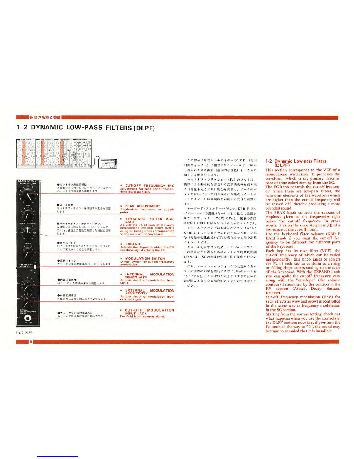
•vcF(«E*Jffll^-r;i^-)
>>*•* -f iK— CD ft* i^'a —/KOWtf.*>l5-r^
D-y^Mfli. lil/l t'tDiiitf". VCO->VCF —
VCAcoWi-r/ffW •«* (fffi!. fife, frfc) 4-3
•*-„ *L?W4Sfc«*ftfcfirl* (&JI2) frvcor*
4-*'-*Hico -*' 3<7->- fci^ff&tt, ceo
VCF01JJ y h *? •-7V *>•>- (Fc) 4--x.>-<
"f-A.-Ci- i-f*T.VCFCi SfffceoafciRfc LtC
ff-urni) to.'hMv*-;- <reiffiftCj^< oS-tlBft
^-(Fc> 4-5!ft§tfiai:i'.ti^>ns0j
i/.-*r)(0'C'KSC-C^&vcFo#^*', *»>«?'*<:
Fig. 6it >>-fc *• -f -tf*-co VCFfr 'KiftcM ifc
i-r :«Mf. vcou/=>**9ttcDJKift un
mtut. vcocD*£&i**5t:fimi i-ro-r, •=*
Jfx^ni-r. *Lt. VCFliWOJ: ?c:, '£«
--» i•> .cto /KHco.vj, ?a.vcfco *?**7<
7H>i- (Fc) cflivr *biff*.
&c*t:. z®7bn0&m<o*i'ikKt£*>x^sm'ft
o»*&? »;u*ot, *.<** fclt&fc<DAta
fj ./a*' >; ttcoJfcrtltD *, <L/„•»*> tK-lft-T 4
g>X,&"<B -?-<,? V>c: J; oTMHMSfcMC Vf
s>^T\ —W$i: l.-«Jls nr* ifc c/i'4*»
Itr*. MflftC, ***jli :> n> •x***u-
*—(;£*#? h*7fflftfcftRH (**«&*, r
p—A-a&ft) a. /Jc|"|fr I-. h"c <lilsl*li*'t;
fc ufti^ttri-.
•VCF (Voltage Controlled Filter)
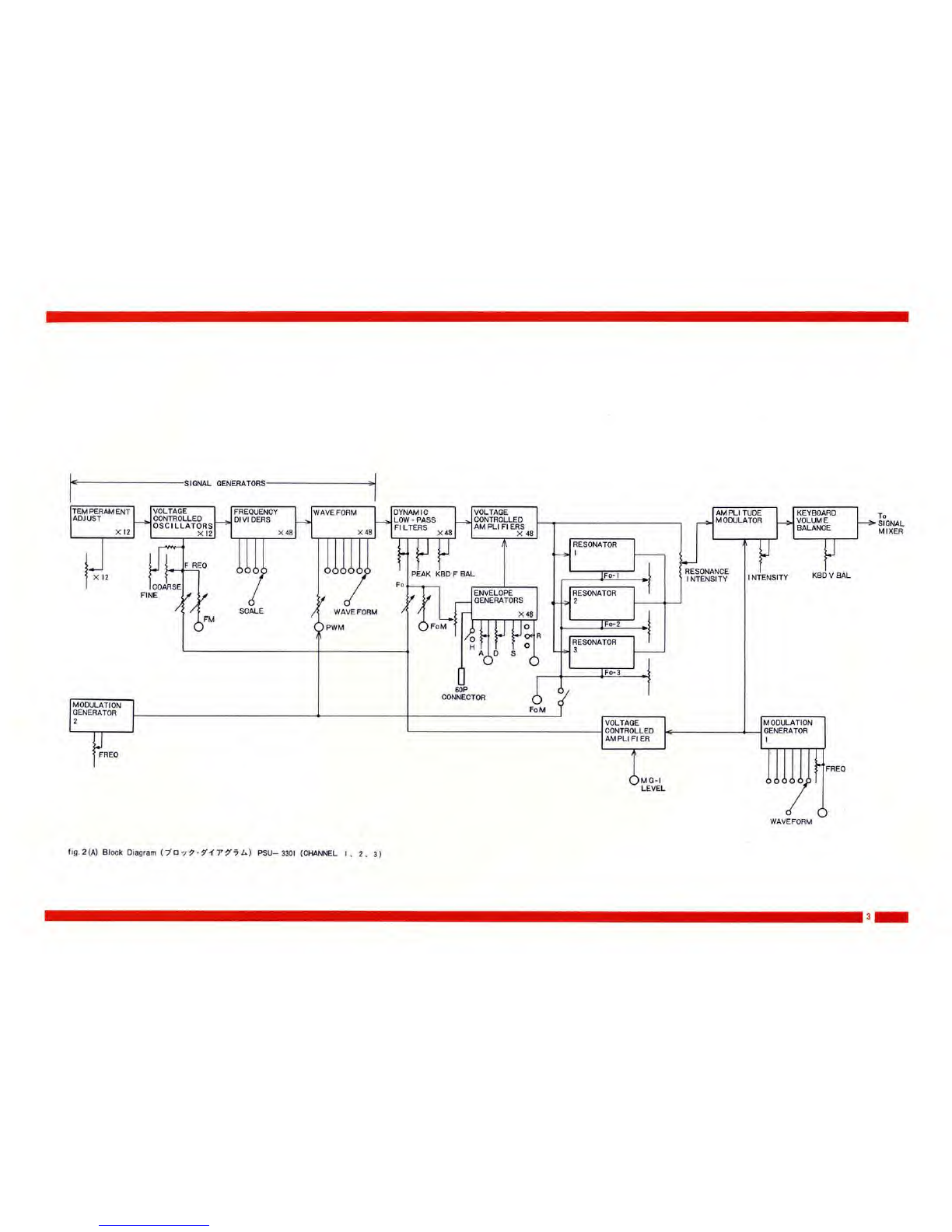
When you look at the block diagram of a
synthesizer, you will almost always see this
series: VCO *VCF -* VGA. These three
basic modules control the three elements
of sound: pitch, timbre, and volume.
The VCO generates awaveform (with a
certain tone color) of acertain pitch
(determined by its frequency).
By shaving off upper harmonic elements of
the waveform, the VCF adds roundness to
the sound.
Anumber of unique synthesizer effects are
created by automatically varying the cut-
off frequency in proportion to volume.
These volume changes are controlled by
the envelope signal. In other words, in this
so-called "expand" effect the envelope
control voltage varies the volume and cut-
off frequency at the same time.
Other VCF effects based on variation of
tone color arc "wow" and "growl". These
arc obtained by using amodulation genera-
tor output signal (the MG is also known as
an LFO or low frequency oscillator). This
cyclic control voltage signal is used to mod-
ulate the VCF. If the operation of the VCF
seems too abstract to you, think of it as a
kind of Watergate.
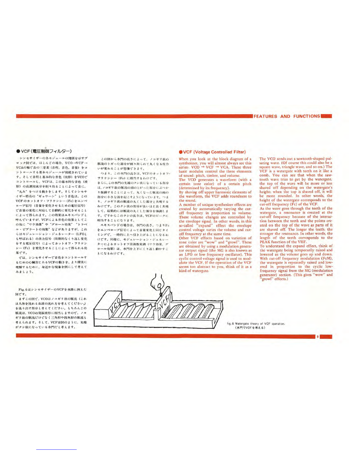
The VCO sends out asawtooth-shaped pul-
sating wave. (Of course this could also be a
square wave, triangle wave, and so on.) The
VCF is aWatergate with teeth on it like a
comb. You can see that when the saw-
tooth wave tries to get by the Watergate,
the top of the wave will be more or less
shaved off depending on the Watergate's
height; when the top is shaved off, it will
be more rounded. In other words, the
height of the Watergate corresponds to the
cut-off frequency (Fc) of the VCF.
As the wave goes through the teeth of the
Watergate, aresonance is created at the
cut-off frequency because of the interac-
tion between the teeth and the points cre-
ated on the top of the wave as parts of it
are shaved off. The longer the teeth, the
stronger the resonance. In other words, the
length of the teeth corresponds to the
PEAK function of the VHF.
To understand the expand effect, think of
the Watergate being temporarily raised and
lowered as the volume goes up and down.
With cut-off frequency modulation (FcM),
the Watergate is repeatedly raised and low-
ered in proportion to the cyclic low-
frequency signal from the MG (modulation
generator) section. (This gives "wow" and
"growl" effects.)
fig. 6Watergate theory of VCF operation.
(*m*VCF £#*.*)