manuals.online logo
Brands
  1. Home
  2. •
  3. Brands
  4. •
  5. Kosnic
  6. •
  7. Accessories
  8. •
  9. Kosnic KPT-MSA012-MWS User manual

Kosnic KPT-MSA012-MWS User manual

www.kosnic.com
Instruction Microwave Sensor KPT-MSA012-MWS V1.0 Page 1
KPT-MSA012-MWS Microwave Sensor Installation
Please read the instructions thoroughly along with the installation instructions for the luminaire and retain for future reference.
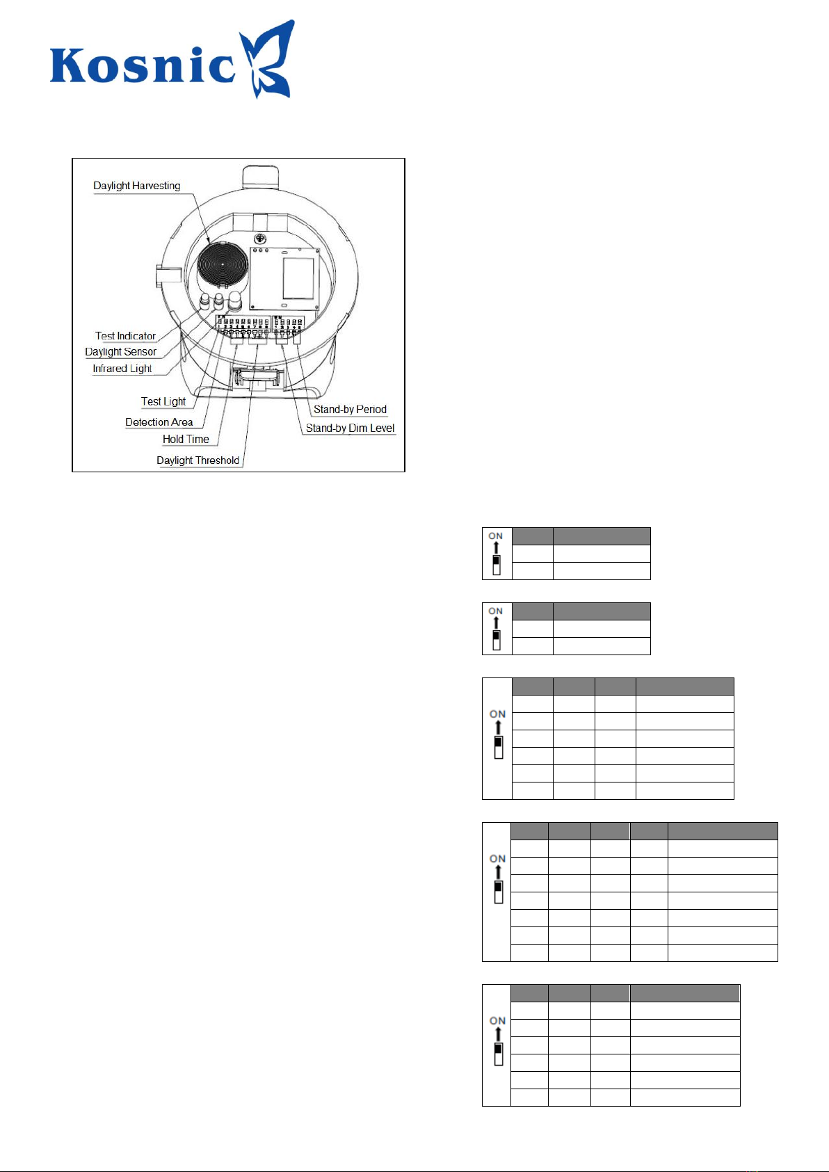
The KPT-MSA012-MWS microwave sensor is suitable for basic on/off control of lighting sources or dimming control and daylight harvesting
with lighting sources that are 1-10V dimmable. The sensor is designed for recessed installation and has a range of up to 5m diameter when
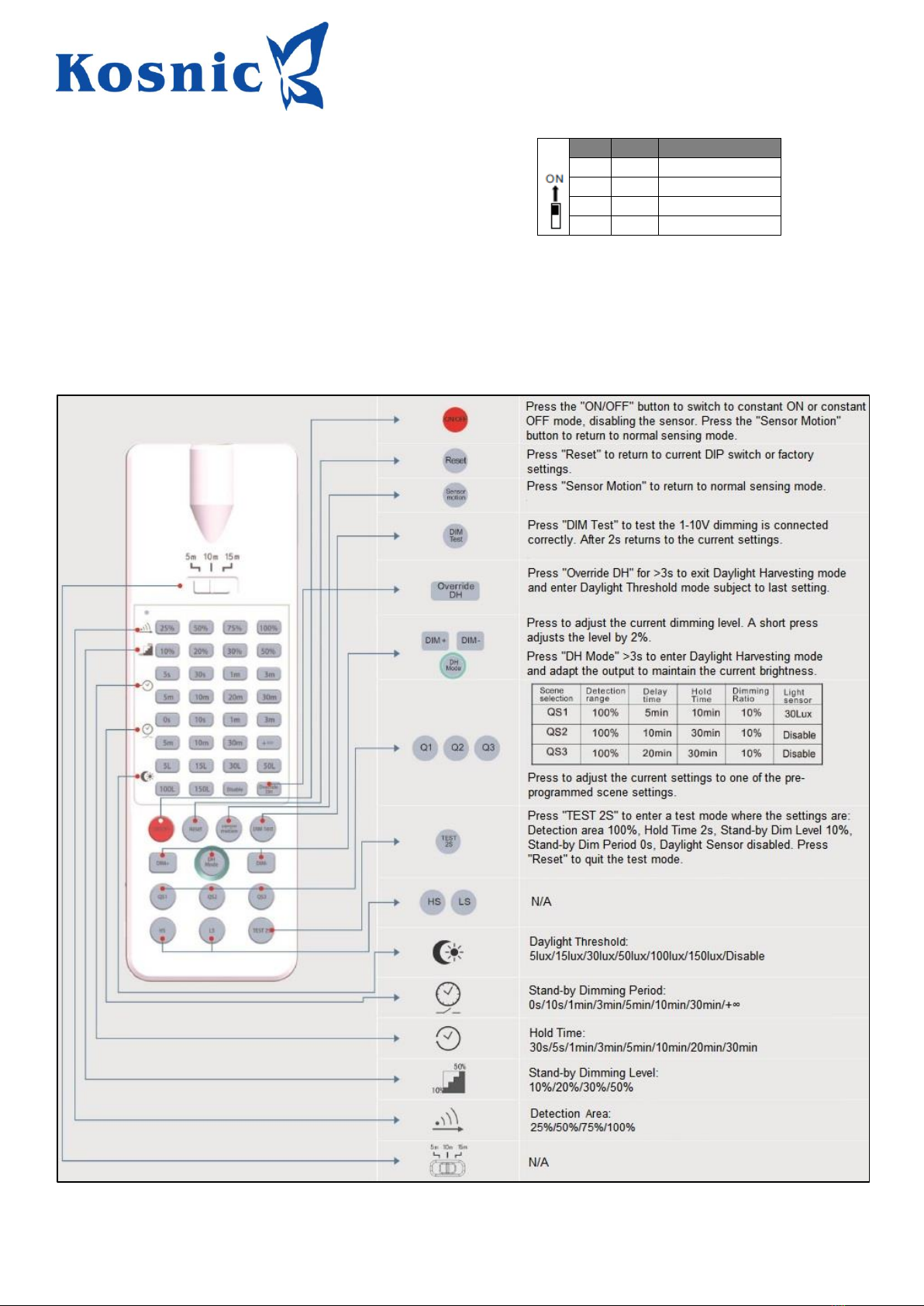
mounted at the maximum height of 6m. The operating parameters can be set via DIP switches or the optional remote control.
Safety Information
•Installation must be carried out in accordance with national building and wiring regulations.
•Before commencing installation and maintenance, turn off and isolate the circuit(s) to be worked on by removing the fuse or switching the
circuit breaker off at the distribution board.
•If you are in any doubt about installing this product, please consult a qualified electrician.
•The sensor is suitable for connection to a 120-277Vac 50-60Hz supply and is IP20 rated.
•The sensor may control the following loads if the load surge is within the limits:
Load
400W (Inductive) 800W (resistive) @ 120Vac
800W (Inductive) 1000W (resistive) @ 277Vac
Surge Capacity
50A (50% Ipeak, twidth = 500uS, 277Vac full load, cold start)
80A (50% Ipeak, twidth = 200uS, 277Vac, full load, cold start)
Installation Information
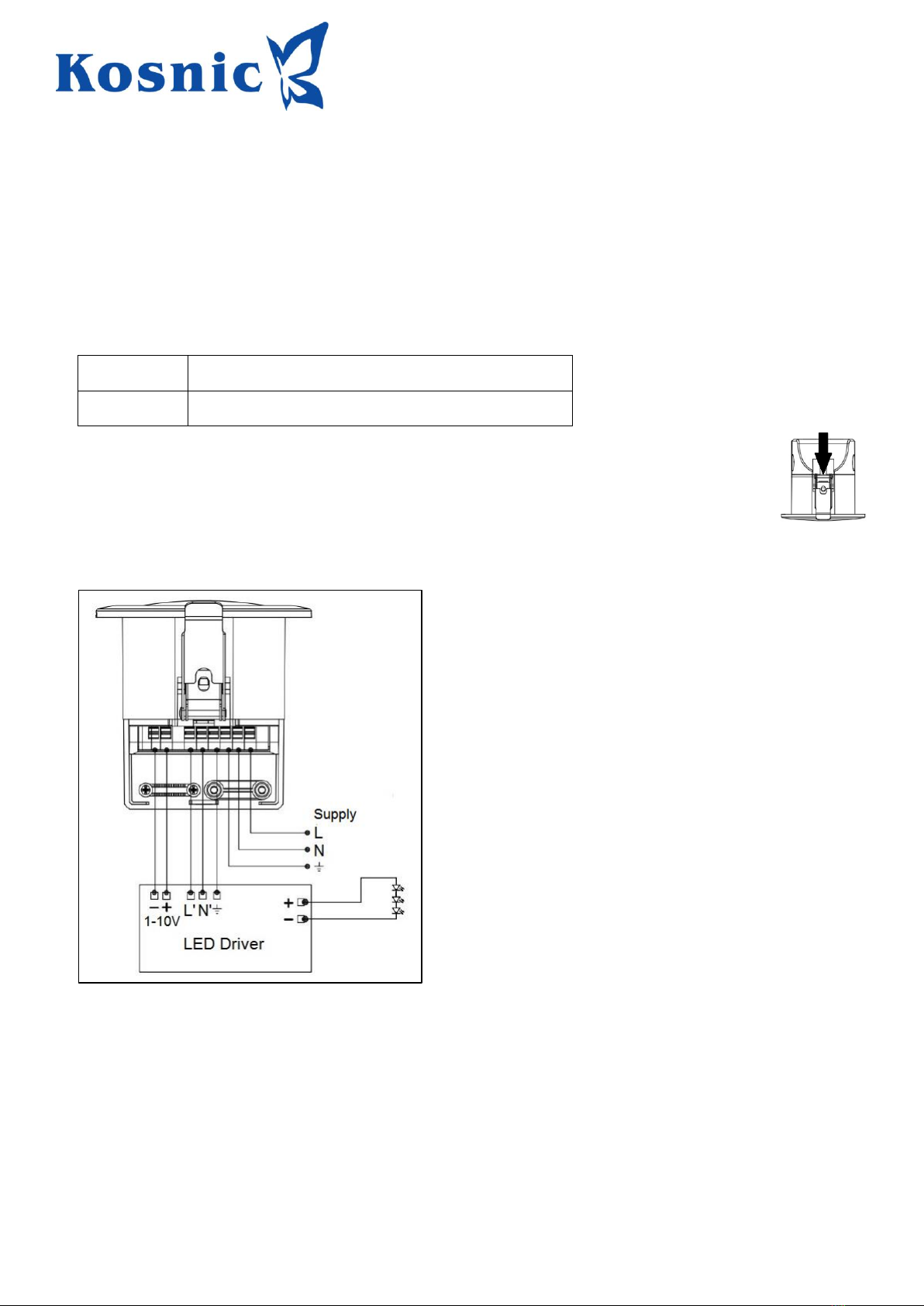
•To remove the sensor terminal cover, insert a small screwdriver blade where indicated opposite and withdraw the cover.
•Connect the supply cable and lighting source (for example the LED driver) to the terminals according to the diagram below.
•If the lighting source is 1-10V dimmable, connect the 1-10V + and –connections as shown to enable dimming and daylight
harvesting operation.
•Ensure that all electrical connections are secure with no loose strands and tighten the cable grips.
•Replace the terminal enclosure cover and reconnect the power supply.
•Refer to the instructions below for operation, DIP switch settings and remote control functions.
Daylight Threshold / Daylight Harvesting
The sensor is aware of the ambient light level and a Daylight Threshold may be set, above which the sensor will not switch the load on.
Additionally, where the load is 1-10V dimmable, Daylight Harvesting may be employed to maintain a constant user-set light level once the
sensor is triggered. When Daylight Harvesting is used the sensor will use the 1-10V dimming control to keep the light level the same as the
dimming level selected by the user by adjusting the light source output up or down as the available ambient light level changes. The remote
control is required for this functionality.
www.kosnic.com
Instruction Microwave Sensor KPT-MSA012-MWS V1.0 Page 2
DIP Switches
•The DIP switches available under the front cover may be used to set the sensor parameters.
•There is a slim slot on the edge of the cover which a small screwdriver blade may be inserted into to remove the cover.
DIP Switch Settings
Test Light
This turns the green sensing indicator on in Test mode to aid
commissioning. In normal operation this should be turned off.
1
Test Light
ON
Test Mode
-
Normal
Detection Area
This is the sensitivity of the sensor. On maximum, the sensor will detect
movement up to 5m from the sensor. Detection area is affected by object
size and motion speed, tested by a 165cm height person walking at 0.5m/s.
2
Detection Area
ON
100 %
-
50 %
Hold Time
This is the time that the light will remain on after presence is no longer
detected.
3
4
5
Hold Time
ON
ON
ON
5 Seconds
-
ON
ON
30 Seconds
ON
-
ON
1 Minute
-
-
ON
3 Minutes
ON
ON
-
20 Minutes
-
-
-
30 Minutes
Daylight Threshold
The sensor can be set to prevent illumination when the ambient light is
above the Daylight Threshold. When set to disabled, the sensor will switch
the light on when presence is detected regardless of the ambient light
level.
6
7
8
9
Daylight Threshold
ON
ON
ON
ON
5 Lux
-
ON
ON
ON
15 Lux
ON
-
ON
ON
30 Lux
-
-
ON
ON
50 Lux
ON
ON
-
ON
100 Lux
ON
ON
ON
-
150 Lux
-
-
-
-
Disabled
Stand-by Period
This is the period which the light source will remain illuminated at the Stand-
by Dim Level once presence has ended.
1
2
3
Stand-by Period
ON
ON
ON
0 s
-
ON
ON
1 Minute
ON
-
ON
3 Minutes
-
-
ON
10 Minutes
ON
ON
-
30 Minutes
-
-
-
+∞
www.kosnic.com
Instruction Microwave Sensor KPT-MSA012-MWS V1.0 Page 3
Stand-by Dim Level
This is the lighting level for the Stand-by Period.
1
2
Stand-by Dim Level
ON
ON
10%
ON
-
20%
-
ON
30%
-
-
50%
Remote Control
While the remote control is useful for testing, altering settings without accessing the DIP switches and for manual override of the sensor, it is
the only way to access the Daylight Harvesting functionality available with 1-10V dimmable loads.
Once a lighting level has been set using the DIM+ and DIM- buttons, pressing the DH Mode for greater than 3 seconds will put the sensor into
daylight harvesting mode where it will adjust the load output to try to maintain the light level as the ambient light changes.
See the diagram below for detailed button information.
www.kosnic.com
Instruction Microwave Sensor KPT-MSA012-MWS V1.0 Page 4
Initialisation
The light will turn on at 100% brightness in the initial energisation, then turn to the brightness set by Stand-by Dim Level 10 seconds later.
During initialisation, no external motion sensing signal will be detected.
Factory Settings
Detection Area: 100%. Hold Time: 5s. Daylight Threshold: Disabled. Stand-by Period: 0s. Stand-by Dim Level: 10%
Notes
•The spacing between sensors should be at least 3m.
•The use of the Daylight Harvesting function requires the remote control.
•If the sensor supply power is switched on and off three times in a row within 2s, sensing is cancelled, and it enters a normal brightness
•mode. Turn the sensor power on and off again to recover the sensor function.
•After each setting by the remote control is selected the load light will flash once, which means the setting is successful.
•There should be no metal plate, glass cover or other materials with high medium density in front of the sensor, which is easy to trigger by
mistake.
•The sensor cannot be installed in a room that vibrates for a long time; the vibration signal will be regarded as a signal to trigger the sensor.
•Turn off the Test Light indicator in normal use to avoid affecting the constant light control.
We hereby declare that this product meets the requirements of the EU Radio Equipment Directive 2014/53/EU. Declaration is issued under the sole responsibility of the
manufacturer. Conforms to:
EN 300 328
Electromagnetic compatibility and Radio spectrum Matters (ERM); Wideband transmission systems; Data transmission equipment operating in the 2,4 GHz
ISM band and using wide band modulation techniques
EN 300 220-1
Electromagnetic compatibility and Radio spectrum Matters (ERM); Short Range Devices (SRD); Radio equipment to be used in the 25 MHz to 1 000 MHz
frequency range with power levels ranging up to 500 mW; Part 1: Technical characteristics and test methods
EN 301 489-1
Electromagnetic compatibility and Radio spectrum Matters (ERM); Electromagnetic Compatibility (EMC) standard for radio equipment and services; Part 1:
Common technical requirements
EN 301 489-3
Electromagnetic compatibility and Radio spectrum Matters (ERM); Electromagnetic Compatibility (EMC) standard for radio equipment and services; Part 3:
Specific conditions for Short-Range Devices (SRD) operating on frequencies between 9 kHz and 40 GHz
EN 301 489-17
Electromagnetic compatibility and Radio spectrum Matters (ERM); Electromagnetic Compatibility (EMC) standard for radio equipment; Part 17: Specific
conditions for Broadband Data Transmission Systems
The Waste Electrical & Electronic Equipment Regulations (WEEE) require that products bearing this symbol must not be disposed of with household waste as they
may contain substances harmful to the environment. The Local Authority can provide advice on recycling.

Popular Accessories manuals by other brands

Gogen PB 200001 WGR installation manual

Gogen

Gogen PB 200001 WGR installation manual

Endress+Hauser Deltapilot S FMB70 Safety instructions

Endress+Hauser

Endress+Hauser Deltapilot S FMB70 Safety instructions

TomTom AD262 instructions

TomTom

TomTom AD262 instructions

Philips AEA1000/37 quick start guide

Philips

Philips AEA1000/37 quick start guide

RayTek RAYCMLTJM operating instructions

RayTek

RayTek RAYCMLTJM operating instructions

Barksdale BPT1000 installation instructions

Barksdale

Barksdale BPT1000 installation instructions

HOMBLI Smart Doorbell 2 manual

HOMBLI

HOMBLI Smart Doorbell 2 manual

Tornado T-3000 Handling instructions

Tornado

Tornado T-3000 Handling instructions

Omron ZN-KMX21 Series instruction sheet

Omron

Omron ZN-KMX21 Series instruction sheet

Takuma AS-1 READER user manual

Takuma

Takuma AS-1 READER user manual

GRAVITY GBGWB123 user manual

GRAVITY

GRAVITY GBGWB123 user manual

Nanometrics Trillium Compact user guide

Nanometrics

Nanometrics Trillium Compact user guide

Philips HF3650 quick start guide

Philips

Philips HF3650 quick start guide

Neo Electronic NAS-WS01Z installation instructions

Neo Electronic

Neo Electronic NAS-WS01Z installation instructions

Hytronik HIM34 quick start guide

Hytronik

Hytronik HIM34 quick start guide

Elkay EZ Series Installation & use manual

Elkay

Elkay EZ Series Installation & use manual

HP 8517B OPERATING & SERVICE MANUAL

HP

HP 8517B OPERATING & SERVICE MANUAL

Gram K3 SERIES quick start guide

Gram

Gram K3 SERIES quick start guide

manuals.online logo
manuals.online logoBrands
  • About & Mission
  • Contact us
  • Privacy Policy
  • Terms and Conditions

Copyright 2025 Manuals.Online. All Rights Reserved.