Kotula's LTM User manual

LTM Large Tilt Mount Installation Instructions
Designed for LCD/Plasma flat panels (37"-61") up to 90.7kg (200lbs).
Warning! This product should only be installed by someone who is experienced with tools, is familiar with basic
wall construction, and fully understands these instructions. Ensure that the supporting wall will safely support the
combined load of the TV screen, and all attached hardware and components. If you cannot identify the type of wall or
you are not certain that the wall is strong enough to support the weight of the mount and TV, you must use a
professional installer, who may need to reinforce the wall. Tighten screws firmly but do not over-tighten, which can
damage the fasteners, greatly reducing their strength. Check carefully to ensure that there are no missing or
defective parts. Do not use any components that appear to be damaged or defective, this may result in damage or
serious injury. Improper installation may lead to damage or serious injury. Do not use this product for any purpose for
which it was not designed. Hollow walls, gypsum board and similar materials will not support the weight of a TV, you
must mount into very strong and solid material behind the wall, such as 2”x4” wood studs or brick/concrete. The wall
mounting hardware supplied with this product is designed for wood stud or concrete/brick walls only. If you are
mounting on a steel stud wall or old cinder block wall, you will need to source alternative wall mounting hardware. The
manufacturer, distributor or dealers are not responsible or liable for any damages, injuries or losses caused by
improper use, assembly, installation or failure to follow the installation instructions or safety warnings. Due to the
small components used in the construction of this unit, small children must be kept away during assembly. If you have
any doubts about the safety of the wall or the installation, your ability to perform the installation properly, or any of the
above warnings, you must use a professional installer.
1
Tools required: 7mm drill bit, 13mm masonry drill bit used for concrete installation, 11/16"(17mm) ratchet wrench ,
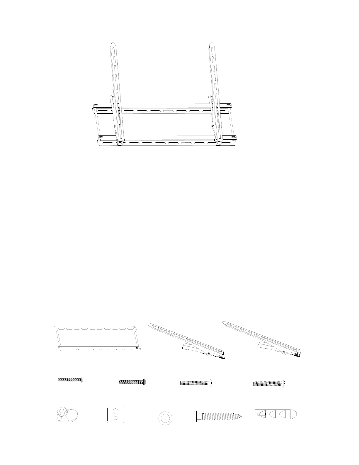
and a Phillips screwdriver. Identify & ensure that you have all components & hardware as per figure 1 below:
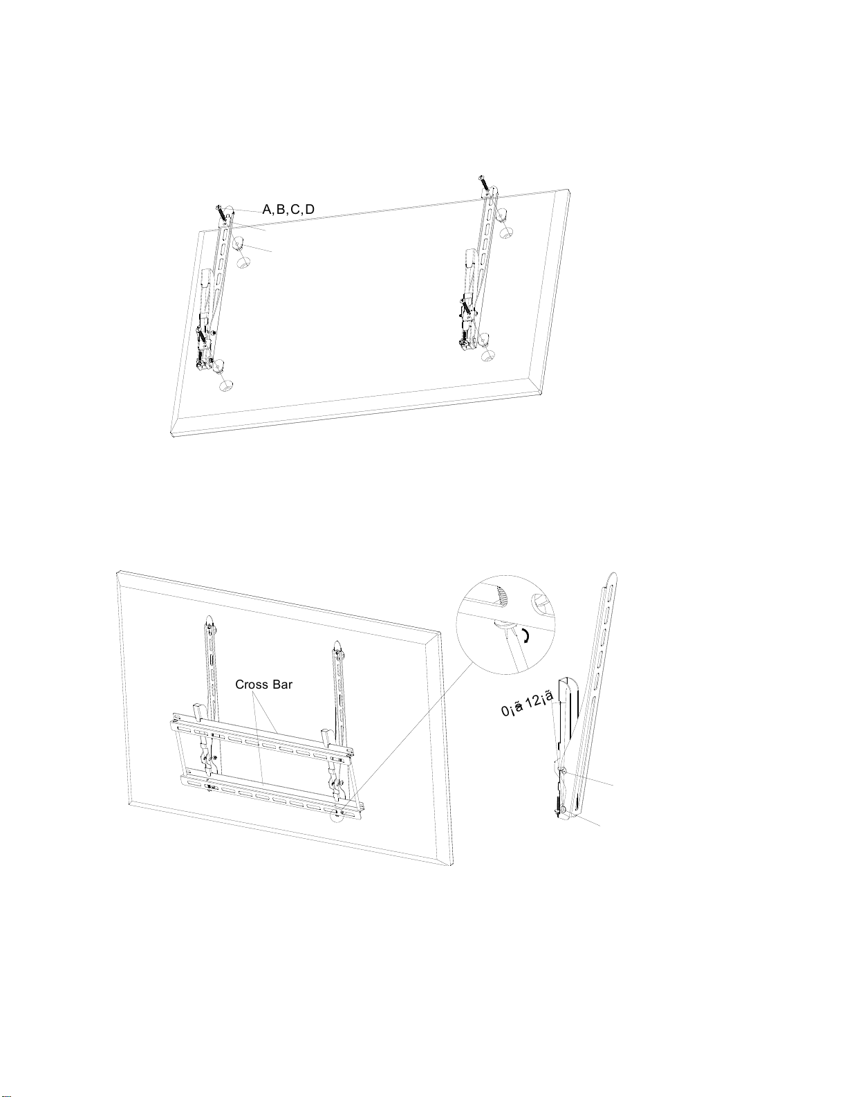
1-WallBracket-(AA) 1-LeftTVinterface arm-(BB) 1-Right TV interface arm-(CC)
4-M4*35 Screws(A)4-M5*35 Screws(B)4-M6*35 Screws(C)4-M8*35Screws(D)
figure 1
4-spacer-(E) 4-square pad-(F) 4-metal washers (G) 4-lag bolts (H) 4-wall anchors-(I)

WALL BRACKET INSTALLATION
Into wood studs:
The wall bracket (AA) must be installed into two wood studs with a separation of at least 40.6 cm (16”). Use a stud
finder to locate two adjacent studs. Using an awl or thin nail, verify the location of the wood stud (as shown in figure
2a). Drill two 7mm diameter holes to a minimum depth of 3.5" (88mm) in each wood stud. Then using four lag bolts
(H) and four metal washers (G), install the wall bracket to the wall, ensuring correct orientation as shown in figure 2b.
Into brick, solid concrete and concrete block:
Using the wall bracket (AA) as a template, mark four evenly spaced holes on the wall. Two holes in the top row slots,
two in the bottom row, making sure that the holes are level. There must be at least 15.2cm spacing between any two
holes. Use masonry drill bits to drill 14mm diameter and 84mm depth holes. Insert the anchor (I) into these holes
respectively, ensuring that they are flush with the wall surface, and then use four lag bolts (H) to install the wall plate
to the wall (as shown in figure 2c).
2
Wall Plate
plaster/
drywall concrete
CORRECT INCORRECT
plaster/
drywallconcrete
Wall Plate
Wall
Plateconcrete
concrete
I
I
HG
Select the hardware that fits your flat panel TV
Caution: Always make sure the television is unplugged before threading any bolt into the back panel. Locate the screw
holes on the back of the LCD/plasma, and select the screws that fit properly. If you do not find the hardware that fits
your LCD/plasma, please contact a local hardware store for correct sizes.
figure2a figure2b figure2c
AA
AA
H
G
H
G
Stud Sensor I
40.6cm
Warning
Never drill into mortar joint.
Concrete must be 2000PSI densit
y
minimum.
Warning
The anchors must be seated firmly against the concrete or
masonry .If mounting to a masonry wall covered with
drywall/plaster, counter bore a hole through the
drywall/plaster around the mounting holes’ location, so that
the anchor can be seated directly against the concrete or
masonry.

Installing the TV interface arms to the back of your flat panel TV
Caution: Never lay the flat panel, face down on the screen, it should be tilted leaning against the wall or other solid
surface, laying the flat panel face down on the screen may lead to permanent damage.
Before installation, the TV interface arms(BB,CC) must be vertically placed and the distance from the flat panel
should be as short as possible .Thread the screws (A,B,C,D) through the square pad (F), the TV interface arms
(BB,CC) ,and spacer ( E) if required, into the flat panel. Tighten the screws firmly with a Phillips screwdriver.
A,B,C,D
E
F
figure 3
Hook the TV with interface arms to the wall bracket.
Caution: Some flat panels are heavy: two strong people are required; lift and position carefully. Lift TV with
interface arms onto the cross bar of the wall bracket (AA), and then lower into place until the hooks are fully seated
on the cross bar of the wall bracket assembly. Lock the screws to prevent the tilting arm assembly falling off the wall
bracket, as shown in figure 4.
Cross Bar
0¡ã~12¡ã
Center lock screw
Adjustable Screw
figure 5figure 4
Angle adjustable function
This product provides an angle adjustable feature. Loosening the adjustable screws and tilting arm assembly to the
desired position, then tighten the adjustable screws, as shown in figure 5.
3
Table of contents