2Krampitz Tanksystem GmbH - Operation and Installation Instructions TTD for Tank System - Issue 04/2011
TABLE OF CONTENTS ................................................................................................................................................................................................. 2
SETTINGS OF THE LIMIT SENSOR FOR DAY TANK TTD ................................................................................................................................................ 3
SETTINGS OF THE OVERFLOW GUARD OF DAY TANK TTD .......................................................................................................................................... 3
INSTALLATION AND TEST CERTIFICATE ...................................................................................................................................................................... 4
PRELIMINARY NOTE ................................................................................................................................................................................................................... 5
ABBREVIATIONS USED ............................................................................................................................................................................................................... 5
1. SAFETY INSTRUCTIONS AND REGULATIONS ........................................................................................................................................................................ 5
1.1 Safety instructions .............................................................................................................................................................................................................. 5
1.2 Operation procedures ......................................................................................................................................................................................................... 6
1.2.1 General operation procedures ..................................................................................................................................................................................... 6
1.2.2 Action to take .............................................................................................................................................................................................................. 6
1.2.3 Instruction of operators ............................................................................................................................................................................................... 6
1.2.4 Repairs and maintenance ............................................................................................................................................................................................ 6
1.2.5 Safety tests and inspections ......................................................................................................................................................................................... 6
1.2.6 Handling fuel oil, Diesel fuel and mineral oil ............................................................................................................................................................... 6
2. DESCRIPTION .......................................................................................................................................................................................................................... 7
2.1 Illustration of the TTD ......................................................................................................................................................................................................... 7
2.2 Intended use of the TTD ...................................................................................................................................................................................................... 7
2.3 Specifications of the TTD ..................................................................................................................................................................................................... 7
2.3.1 Dimensions and weights of the TTD ............................................................................................................................................................................. 7
2.3.2 Connections of the TTD ................................................................................................................................................................................................ 8
2.3.3 Filling and discharge rates of the TTD from tank trucks ............................................................................................................................................... 8
2.3.4 Plant layout scheme .................................................................................................................................................................................................... 8
2.4. Units of the TTD - standard equipment .............................................................................................................................................................................. 9
2.4.1 The tank vessel ............................................................................................................................................................................................................ 9
2.4.2 The static vacuum leakage indicator ............................................................................................................................................................................ 9
2.4.3 The rupture disk ......................................................................................................................................................................................................... 9
2.4.4 The transport plug ........................................................................................................................................................................................................ 9
2.4.5 The ball valve ............................................................................................................................................................................................................... 9
2.4.6 Corrosion protection for indoor installation ................................................................................................................................................................. 9
2.4.7 The nameplate ............................................................................................................................................................................................................. 10
2.5. Connection kit .................................................................................................................................................................................................................... 10
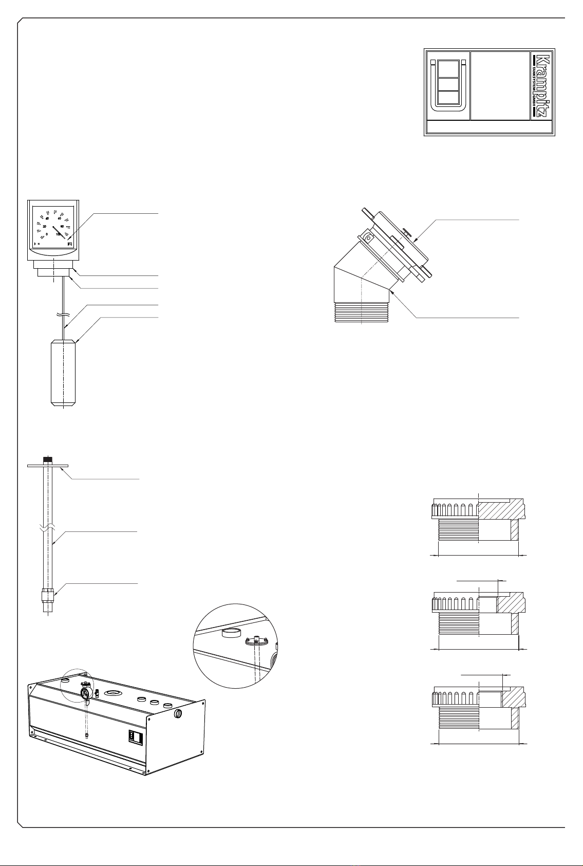
2.5.1 The level indicator ........................................................................................................................................................................................................ 10
2.5.2 The filling socket .......................................................................................................................................................................................................... 10
2.5.3 The suction pipe - machine flow pipe .......................................................................................................................................................................... 10
2.5.4 The adapter set ............................................................................................................................................................................................................ 10
2.5.5 The machine return pipe .............................................................................................................................................................................................. 11
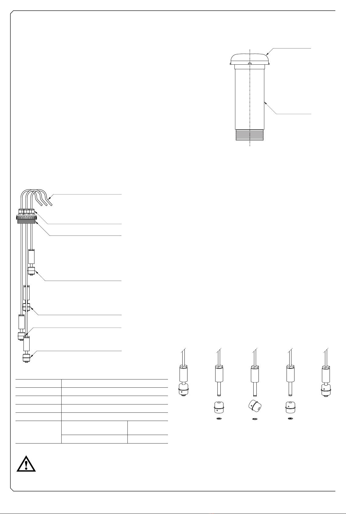
2.5.6 The bleeding adapter with hood .................................................................................................................................................................................. 11
2.6. Units of the TTD - special design ........................................................................................................................................................................................ 11
2.6.1 The level sensor ........................................................................................................................................................................................................... 11
2.6.1.1 The level switch (miniature alarm) ..................................................................................................................................................................... 11
2.6.1.2 The electronic volume indicator ......................................................................................................................................................................... 12
2.6.1.3 Floating switch volume indicator and dipstick with dipstick pipe plug .............................................................................................................. 12
2.6.2 Bearing charts ............................................................................................................................................................................................................ 12
2.6.2.1 Bearing charts for TTD 250,TTD 500 ................................................................................................................................................................ 12
2.6.2.2 Bearing charts for TTD 750,TTD 990, TTD 1500 and TTD 1950 ......................................................................................................................... 13
2.6.3 The electronic leakage indicator .................................................................................................................................................................................. 14
2.6.4 The electronic vacuum leakage indicator ..................................................................................................................................................................... 14
2.6.5 The oil warning sensor with alarm and evaluation unit .............................................................................................................................................. 15
2.6.5.1 Function of the oil alarm .................................................................................................................................................................................... 15
2.6.5.2 Configuration of the oil alarm ........................................................................................................................................................................... 15
2.6.6 The overfill guards ....................................................................................................................................................................................................... 15
2.6.6.1 The limit sensor with PTC thermistor - only for fuel oil and Diesel fuel .............................................................................................................. 15
2.6.6.2 The overfill guard with evaluation logic ............................................................................................................................................................. 15
2.6.6.3 Overview: Possible switching points and control instructions ............................................................................................................................ 16
2.6.7 The pump combination ................................................................................................................................................................................................ 16
2.6.7.1 Other pumps from the delivery range of Krampitz Tanksystem GmbH ............................................................................................................... 16
2.6.8 The tank heater............................................................................................................................................................................................................. 16
2.6.9 The wall brackets ......................................................................................................................................................................................................... 16
2.6.10 The supporting column .............................................................................................................................................................................................. 17
2.6.11 The Krampitz special nut with captive washer ........................................................................................................................................................... 17
2.6.12 The feet ...................................................................................................................................................................................................................... 17
3. START-UP ................................................................................................................................................................................................................................. 17
3.1 Transport of the TTD ............................................................................................................................................................................................................ 17
3.2 Wall mounting of the TTD ................................................................................................................................................................................................... 17
3.3 Setting up the TTD on feet / supporting column .................................................................................................................................................................. 18
3.4 First start-up ....................................................................................................................................................................................................................... 18
3.5 Operation sequence ............................................................................................................................................................................................................ 18
4. DOCUMENTATION .................................................................................................................................................................................................................. 19
5. WARRANTY ............................................................................................................................................................................................................................. 19
TABLE OF CONTENTS