1.2.2 MAIN OUTPUTS
Maximum Amplitude: 7V rms open circuit (balanced output, 14V rms end-to-end); 3.5Vrms; +48dBm
into 50 ohm load (balanced output, 7V rms end-to-end).
Impedance: Constant 50 ohms.
Maximum Current: 75mA rms.
Minimum Amplitude: <0.2mV.
Amplitude Flatness: ±0.02dB, 1Hz to 110kHz.
Amplitude Stability:
Vs. Time: 0.01% in 1 hour or less.
Vs. Temperature: 0.05%/°C.
Vs. Line: <0.001% for a 10% change in line voltage.
Amplitude Control: A 4-position push-button attenuator calibrated in 20dB steps from 0dB to –60dB,
Accuracy, ±0.25dB/20dB step; Volts rms control with greater than 30dB of coverage calibrated in volts.
Accuracy: ±20% of setting.
Main Output Distortion:
Frequency Distortion % Distortion (dB)
1Hz to 10kHz <0.0005 –106
10kHz to 20kHz <0.0018 –95
20kHz to 50kHz <0.0056 –85
50kHz to 110kHz <0.01 –80
Hum and Noise: Greater than 110dB below signal (10Hz to 20kHz detector bandwidth).
1.2.3 FIXED OUTPUT
Amplitude: 7V rms open circuit; 3.5V rms (+13dBm) into 600 ohm load.
Impedance: Constant 600 ohms.
Amplitude Flatness, Amplitude Stability and Distortion: Same as Main Output.
Phase Accuracy (180°, top BNC, Main Output): 1Hz to 10kHz, ±0.4°; 10kHz to 110kHz, ±5°.
1.2.4 QUADRATURE OUTPUT
Amplitude: 7V rms open circuit; 3.5V rms (+13dBm) into 600 ohm load.
Impedance: Constant 600 ohms.
Amplitude Flatness: ±2dB, 1Hz to 110kHz.
Amplitude Stability: Same as Main Output.
Phase Accuracy (–90°): 1Hz to 1kHz, ±0.2°; 1kHz to 10kHz, ±1°; 10kHz to 110kHz, ±10°.
1-2 - General Description
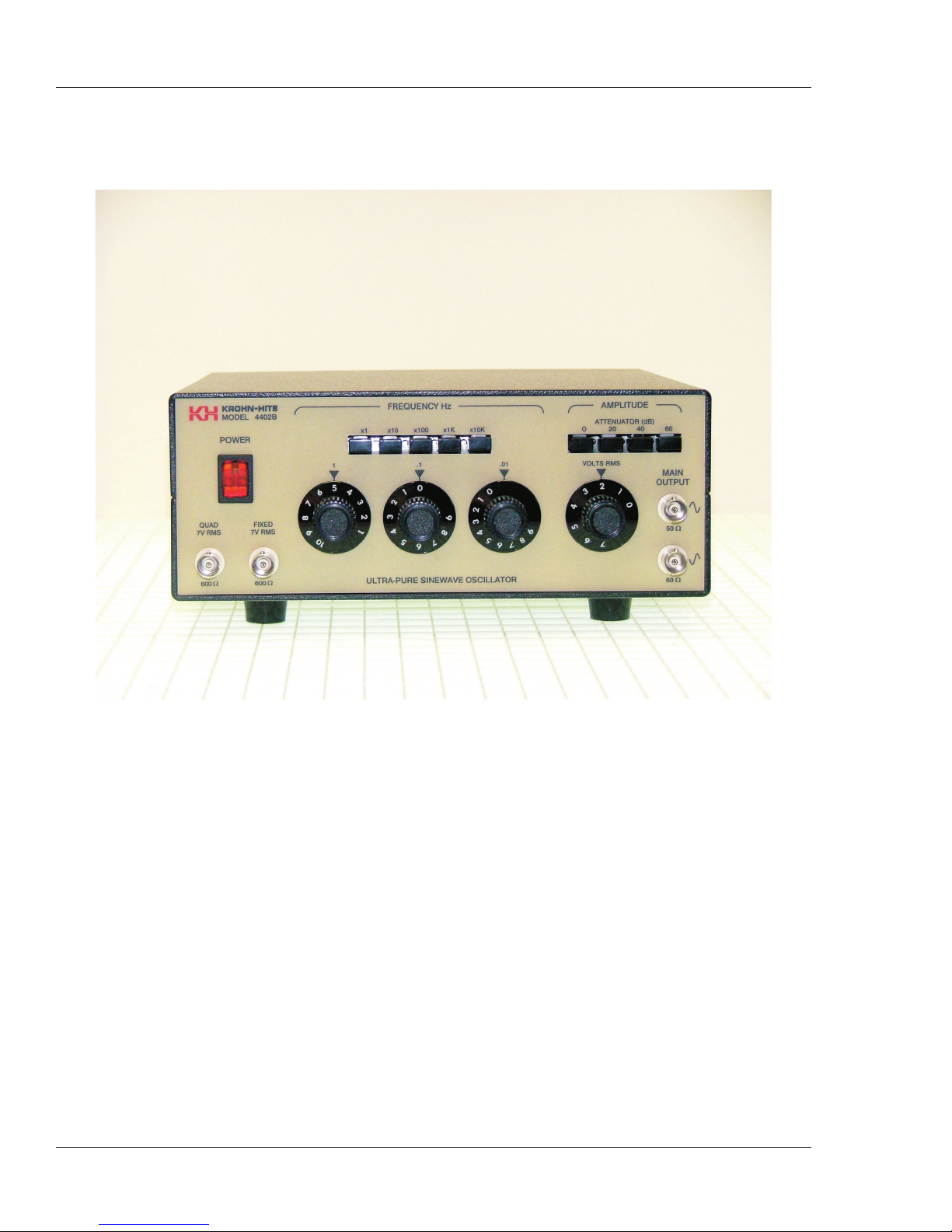
Model 4402B Ultra-Pure Sinewave Oscillator