Kroll W 12 VA User manual

W12VA
880806
BETRIEBSANLEITUNG OWNER’S MANUAL MODE D’EMPLOI
D
Seite 2- 9
Dieses Gerät ist nach den geltenden Vorschriften anzuschlieȕen und darf nur im Freien aufgestellt werden!
Vor Installation und Inbetriebnahme des Gerätes Anleitungen beachten!
Vor brennbaren Materialien mindestens 2 m Abstand einhalten.
Nach jedem Einsatz und anschlieȕender Auȕerbetriebnahme über die Bedienungsknöpfe ist auch das
Flaschenventil zu schlieȕen.
GB
page 10 - 17
This machine has to be installed according to actual regulations and should be used only outside !
Read carefully this manual before installation and start-up !
Keep away min. 2 m from inflammable materials.
Do not forget to close the bottle valve after each use and shut-down using the control button !
F
page 18 - 25
Lisez toujours les instructions avant d’assembler et d’utiliser cet appareil.
Il faut installer cet appareil en respectant les règlements en vigueur.
A utiliser uniquement à l’extérieur et ne jamais à l’intérieur.
Cet appareil ne peut pas être utilisé dans des sous-sols ou en dessous du niveau du sol.
Garder l´appareil à une distance d´au moins 2 m de matériaux inflammables.
Après chaque usage fermer la vanne de la bonbonne.
Stand Juni 2008

2
W12VA
DE, Bedienungsanleitung
Terrassen-Gasglühstrahler für Flüssiggase
Artikel Nr. S00121, Typbezeichnung LIP 10 TGG
Kategorie: I3B/P
Juni 2008 mit Gas-Kippschutzventil
Technische Änderungen Installation nur durch autorisiertes Fachpersonal.
vorbehalten!
1 Allgemeines
Es handelt sich um einen Terrassen - Gasglühstrahler, der mit Flüssiggas (Butan oder Propan) betrieben
wird. (Die Montage- und Bedienungsanleitungen der beigelegten Komponenten beachten)
1.1 Ausstattung, Konstruktion
Transportabler Terrassen-Gasglühstrahler mit Säule, Gehäuse: Edelstahl,
Kroll GmbH, Wärme- und Lüftungstechnik,
71737 Kirchberg/Murr
1.2 Technische Daten
• Betrieb mit Flüssiggas Propan/Butan:
50 mbar
• Nennwärmebelastung: 12,5 kW
• Kleinstellung: 6.5 kW
• Verbrauch: 780 g/h
• Kleinstellverbrauch: 510 g/h
• Gewicht: ca. 30 kg
Das Gerät wurde einer
Baumusterprüfung unterzogen und ist
mit einer CE-Kennzeichnung
versehen.
1. Fuȕ,
2. Flaschenbehälter,
3. Standsäule,
4. Abdeckung,
5. Bedienungsteil,
6. Lufteinlassgitter,
7. Brenner,
8. Brennraum,
9. Reflektor Durchmesser 950 mm
10. Gasventil,
950
und Schlauchbruchsicherung

3
W12VA
2 Hinweise zur Sicherheit
Beachten Sie bitte auch die Richtlinien für den Umgang mit Flüssiggas, die Sie an jeder Verkaufsstelle
erhalten.
• Dieser Heizstrahler darf nicht in geschlossenen Räumen verwendet werden!
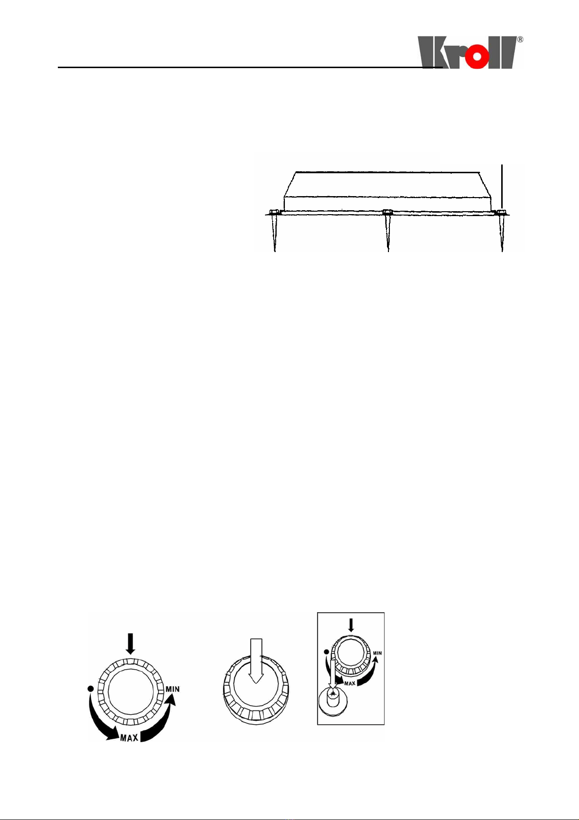
• Das Gerät ist auf einerfesten, ebenenund stabilenUnterlage windgeschützt aufzustellen und bei
Bedarf mit Schrauben an vorgesehener Stelle zu befestigen.
Die Gasentnahme darf nur bei stehender Flasche erfolgen.
• Während des Betriebes muss ein sicherer Abstand von 2m vom Gerät zu brennbaren Materialien und
Stoffen eingehalten werden.
• Das Gerät ist nicht unbeaufsichtigt während des Betriebes zu lassen.
• Der Niederdruck-Gasanschlussschlauch ist vor möglichen Beschädigungen zu schützen und muss
regelmäȕig kontrolliert werden. Es ist darauf zu achten, dass der Schlauch nicht geknickt wird.
Beschädigte oder poröse Schläuche sind auszuwechseln.
• Während des Betriebes darf das Gerät nicht zu einem anderen Standort bewegt bzw. transportiert werden.
• Reparaturen und Wartungen am gastechnischen Teil des Gerätes dürfen nur von hierfür autorisiertem
Fachpersonal durchgeführt werden.
Das Gerät muss in regelmäȕigen Abständen, hier 2 Jahre, von Sachkundigen untersucht und gewartet
werden.
• Auȕerbetriebnahme bei Störungen: das Absperrventil der Gasflasche ist nach Gebrauch oder im Falle
einer Störung sofort zu schlieȕen.
• Inbetriebnahme nach Störungen: Der Heizstrahler darf nur nach Behebung der Störung wieder in Betrieb
genommen werden.
• Der Brenner, vor allem die Lufteintrittsöffnungen, ist von Verschmutzungen freizuhalten.
• Die Dichtheit der Anlage ist möglichst oft und nach jeder Neuaufstellung zu kontrollieren.
Siehe Abschnitt: Dichtheitsprüfung.
• Im Freien aufgestellte Flaschen müssen gegen den Zugriff Unbefugter gesichert sein. Hierzu ist die
vorgesehene Sicherung der Haube des Flaschenraumes abzusichern.
• Bewahren Sie die Flüssiggasflasche niemals unter Erdgleiche oder an unbelüfteten Plätzen auf (siehe
„Vorschriften und Hinweise zur Sicherheit“).
• Die Flüssiggasflasche ist vor Wärmeeinwirkung (starke Sonnenbestrahlung) zu schützen.
• Die Aufstellung von Flüssiggasflaschen ist nicht zulässig in Fluren, unter Erdgleiche, in Treppenräumen,
in Durchgängen und Durchfahrten von Gebäuden, sowie in ihrer unmittelbaren Nähe. Flüssiggasflaschen,
auch leere, sind stehend aufzubewahren. Die Ventile müssen mit Ventilschutzkappen und
Verschlussmuttern versehen werden.
2.1 Rechtsverordnungen, technische Regeln und Richtlinien
Bei der Aufstellung sind folgende Vorschriften zu beachten:
• TRF „Technische Regeln Flüssiggas“,
Bezug: BGW, Wirtschafts- und Verlagsgesellschaft Gas und Wasser GmbH, Wirmer-Straȕe 1-3,
5300 Bonn 1,
• Einschlägige Unfallverhütungsvorschriften (VBG 21 usw.)
Bezug: beispielsweise Carl Heymanns Verlag KG,
Gereonstr. 18-32, 5000 Köln 1,
• „Richtlinien für die Verwendung von Flüssiggas“,
Bezug: beispielsweise Carl Heymanns Verlag KG,
Gereonstr. 18-32, 5000 Köln 1,

4
W12VA
2.1.1 Dichtheitsprüfung
Nach dem Geräteaufbau, im folgenden beschrieben, sind alle gasführenden Verbindungsstellen auf Dichtheit
zu kontrollieren. Hierzu ist ein nicht korrodierendes, schaumbildendes Mittel zu verwenden. Das gut
schaumbildende Mittel ist auf die Gasverbindungen aufzutragen.
Die Dichtheit ist gewährleistet, wenn sich keine Bläschenbildung zeigt.
Eine Dichtheitsprüfung mit offener Flamme ist strengstens untersagt.
3 Geräteaufbau und
Betriebsbereitschaft
3.1 Anschluss des Gerätes
Karton auspacken, die Verpackung öffnen und den Inhalt auf
Vollständigkeit überprüfen (Siehe Ausstattung Seite 2), Gerät
zusammenbauen.
3.2 Teile zum Anschluss des Gerätes
11kg-Propanflasche mit fest eingebautem Entnahmeventil.
Hinweis: graue Propanflasche, tauschbar bei jedem
Flüssiggasvertrieb gegen eine gefüllte Flasche. Andersfarbige
Flüssiggasflaschen bis zu einem Füllgewicht von 14 kg sind
nach gleichem System anschlieȕbar, fest eingestelltes DIN-
DVGW-zugelassenes Druckregelgerät nach DIN 4811, Teil 1,
max. Entnahme 1.5 kg/h, Betriebsdruck: 50 mbar, passend zur ver-
wendeten Gasflasche + Kippschutzventile + Schlauchbruchsicherung
Hinweis: Die in anderen europäischen Ländern verkauften
Druckregelgeräte sind meist für einen Ausgangsdruck von 30
mbar geeignet. In deutscher Einstellung ist das Gerät mit einem
Druckregelgerät für einen Ausgangsdruck von 50 mbar zu
verwenden.
Der Anschlussdruck ist mit dem am Gerät angebrachten
Typenschild und mit dem auf dem Druckregelgerät
angegebenen Ausgangsdruck zu vergleichen. Die Drücke
müssen übereinstimmen.
DIN-DVGW-anerkannte Schlauchleitung nach DIN 4815, Teil 2,
in ausreichender Länge bis höchstens 40 cm, die eine knickfreie
Montage erlaubt.
Lecksuchmittel (z.B. Lecksuchspray).

5
W12VA
3.3 Flaschenanschluss
3.3.1 Dichtung
Augenscheinlich das Vorhandensein und den ordnungsgemäȕen Zustand (keine Beschädigung) der Dichtung
des Flaschenventils kontrollieren (auch bei jedem Flaschenwechsel!)
Es sind keine zusätzlichen Dichtungen zu verwenden.
3.3.2 Anschluss Druckregelgerät, Kippschutzventil + Schlauchbruchsicherung
Die Überwurfmutter des Druckregelgerätes ist durch Linksdrehung (Achtung, Linksgewinde) von Hand mit
dem Flaschenventilgewinde zu verbinden. Es ist kein Werkzeug zu verwenden, da hierdurch die
Flaschenventildichtung beschädigt werden kann und somit die Dichtheit nicht mehr gewährleistet wäre.
Das Druckregelgerät sollte hierbei in waagerechter Position gehalten werden.
Abbildung 2, Druckregler und Schlauchanschluss
3.3.3 Einbauanweisung Gasanschluss
Vor erstem Betrieb ist der beiliegende Gasanschluss mit Gewindeende (Linksgewinde G 1/4 LH) für den
Schlauch zu installieren.
Am Anschluss des Gasventils ist das Gasanschlussrohr mit Hilfe der Überwurfmutter fest zu verbinden.
Überwurfmutter und das Gegengewinde am Gasventil haben Rechtsgewinde und müssen daher zwecks
Verbindung rechtsherum gedreht werden. Das Kontern/Gegenhalten an der SW13 Aufschraubmutter darf
nicht vergessen werden. Am Ende ist gut anzuziehen, um die metallisch wirkende Abdichtung sicher zu
erreichen.
Achtung:
Mit zu kräftigem Anziehen bzw. mit schrägem Ansetzen des Anschlusses kann das Gewinde der
Verschraubung zerstört werden. Die ordnungsgemäȕe Dichtheit kann in diesem Fall nicht wieder hergestellt
werden.
Am zusammengebauten, jedoch noch nicht in das Gerät eingesetzten Gasanschluss ist die Dichtheit aller
Verbindungen, sowie der anderen gasführenden Teile mit einem schaumbildenden Mittel (Lecksuchspray)
und Luftdruck von 150 mbar (U-Rohr-Manometer) zu überprüfen.
Die angegebenen Arbeiten dürfen nur von einem zugelassenen Fachmann vorgenommen werden
.
3.3.4 Schlauchanschluss
Die Schlauchleitung ist mit dem Ausgangsgewinde des Druckregelgerätes unter Verwendung eines
Schraubenschlüssels SW 17 durch Linksdrehung (Überwurfmuttern mit Kerbe gekennzeichnet) zu
verbinden.
Beim Anziehen der Überwurfmuttern muss durch Festhalten des Druckregelgerätes mit einem
Das Gas-Kippschutzventil schließt bei gefährlicher
Neigung (Neigungswinkel ca. 40°) die Gaszufuhr
zum Brenner zuverlässig ab, wodurch eine eventuelle
Brandgefahr oder der Austritt von unverbranntem Gas
sicher vermieden wird.
Nach dem Aufstellen des Terassenheizgerätes wird
die Gaszufuhr automatisch wieder geöffnet.
Das Gas-Kippschutzventil wird mit geregeltem
Gasdruck betrieben und kann für Terassenheiz-
geräte eingesetzt werden, die mit 30 mbar oder
50 mbar betrieben werden.
Bei gewerblichem Betrieb muß der
Gasdruckregler - Artikel-Nr. 040194
eingesetzt werden.
+ Schlauchbruchsicherung - Art.-Nr. 040195
+ Kippschutzventil - Artikel-Nr. 035635

6
W12VA
Schraubenschlüssel gekontert werden.
Die Verbindung des anderen Endes der Schlauchleitung mit dem Gewinde des Anschlussstutzens des Gerätes
(Auȕengewinde G 1/4" LH) erfolgt, wie oben bereits angegeben. Beim Anziehen ist links herum zu drehen
und in jedem Fall mit einem zweiten Schraubenschlüssel SW 14 gegenzuhalten. Dies kann nur bei
herausgezogenem Brenner geschehen, da in diesem Fall die Dichtheit aller Verbindungen, die unter
Gasdruck stehen können, geprüft werden muss.
3.3.5 Hinweis für eventuell notwendigen Schlauchwechsel
Falls die Schlauchleitung, beispielsweise bei einer Beschädigung, gewechselt werden muss, sind die
Verbindungen beider Enden, SW17, zu lösen, wobei in jedem Fall der Anschlussstutzen des Gerätes mit
einem zweiten Schraubenschlüssel SW14 gegenzuhalten ist bzw. Das Druckregelgerät von Hand festzuhalten
ist.
In umgekehrter Reihenfolge ist, wie bereitsoben beschrieben, die neue Schlauchleitung wieder zu montieren.
Ein zugelassener Fachmann ist zu bemühen.
3.3.6 Dichtheitsprüfung
Anschlieȕende notwendige Dichtheitsprüfungen sind an allen gasführenden Teilen vor dem Aufsetzen oder
Einsatz des Brennerkopfes durchzuführen.
Mit einem Lecksuchmittel sind alle Verbindungsstellen, sowie die Schlauchleitung unter Luftdruck auf
Dichtheit zu kontrollieren. Die Dichtheit ist sichergestellt, wenn sich keine Blasenbildung zeigt.
Gegebenenfalls ist ein zugelassener Fachmann zu bemühen.
Eine Dichtheitsprüfung mit offener Flamme ist nicht zulässig.
3.4 Öffnen und Schlieȕen der Gaszufuhr
Das Öffnen und Schlieȕen der Gaszufuhr zum Brenner kann nur durch Betätigen des Flaschenventils
erfolgen (siehe „Inbetriebnahme“ und „Außerbetriebnahme“).
4 Inbetriebnahme
Das Flaschenventil durch Linksdrehung öffnen und unverzüglich den Zündbrenner mit Hilfe des
Piezozünders bei gleichzeitigen Eindrücken des mittleren Druckknopfes mit Sternsymbol anzünden. Nur die
Zündflamme brennt nun.
Bei Betätigung des oberen (groȕen Flammensymbols) oder unteren Knopfes (kleines Flammensymbol) wird
auf vollen Betrieb bzw. auf Kleinstellung geschaltet.
ACHTUNG! Bei erstem Gebrauch des Gerätes sollte der Fachmann anwesend sein und den Betreiber
einweisen.
Es ist auf vollständigen Austritt der Luft aus der Gasleitung zu achten. Die Entlüftung der Gasleitung kann
einige Zeit in Anspruch nehmen.
Nach erfolgreicher Zündung ist das Gerät ca. 10 Minuten bei Volllast zu betreiben. Die zu Beginn
auftretende Rauchentwicklung ist auf verbrennende Reste von Maschinenfett und Öl zurückzuführen und
hört nach ca. 10 Minuten auf. Eine bläuliche Verfärbung des Brennergitters erfolgt zwangsläufig aufgrund
der starken Hitzeentwicklung. Diese ist jedoch ohne jeglichen Einfluss auf die Qualität des verwendeten
Materials.
5 Auȕerbetriebnahme
Nach Gebrauch des Gerätes durch Betätigung des mittleren Knopfes die Gaszufuhr zum Hauptbrenner
schlieȕen. Erst danach ist die Gasflasche am Gasventil der Flasche zu schlieȕen.
(Siehe hierzu „Hinweise zur Sicherheit“, Seite 2).
6 Störung, Schlieȕen der Gasflasche
Schlieȕen Sie nach Gebrauch oder im Falle einer Störung immer das Absperrventil der Gasflasche.

7
W12VA
7 Entfernen des Druckregelgerätes
Entfernen Sie das Druckregelgerät, indem Sie die Verbindungsmutter im Uhrzeigersinn lösen.
8 Bodenbefestigung
Bei Gefährdung durch starke Winde ist das Gerät ist mit Hilfe von zusätzlichen Verankerungen am
Aufstellungsboden zu befestigen. Bei zu
starkem Wind ist das Gerät auszuschalten
und die Flasche zu schlieȕen. Das Gerät
sollte aus dem Gefahrenbereich entfernt
werden.
Das Gerät sollte in heiȕem Zustand bzw.
während des Betriebes nicht transportiert
werden; erforderlichenfalls Gerät auȕer
Betrieb nehmen und dann zu versetzen.
9 Reinigung und Pflege
Lackierte Flächen mit weichem, feuchtem Lappen abwischen. Nur für Lack geeignete Putzmittel verwenden.
Kratzende und scharfe Putzmittel vermeiden.
Gegebenenfalls sind Verschmutzungen vom Brenner zu entfernen.
10. Bedienung
Anzünden der Flamme
1. Offnen Sie die Gasflasche.
2. Drehen Sie im Uhrzeigersinn den Bedienungsknopf des Kontrollventils in eine Position zwischen max.
und min.
3. Den Bedienungsknopf eindrücken und festhalten.
4. Drücken Sie den Zündknopf so oft ein bis die Flamme entsteht.
5. Halten Sie den Bedienungsknopf 5 bis 10 Sekunden eingedrückt bei entstehender Flamme.
6. Lassen Sie den Bedienungsknopf los und achten Sie darauf, dass die Flamme noch brennt.
7. Bei Fehlzündung wiederholen Sie die Handlungen 3 bis 6.
8. Stellen Sie den Bedienungsknopf nach Wunsch ein.
Das Auslöschen der Flamme
1. Setzen Sie den Bedienungsknopf am Kontrollventil in den Stand „0“ um die Flamme zu loschen.
Achten Sie darauf, dass die Flamme tatsächlich ausgelöscht ist.
2. Schließen Sie das Ventil an der Gasflasche.
Schrauben o.ä. im Boden
Abbildung 3, Bodenbefestigung

8
W12VA
11. Die Aufstellung des Geräts
SCHRITT
1
xStellen Sie die drei Stehhaken auf
die runde Bodenplatte wie
vorgezeigt.
xVerwenden Sie zur Befestigung
dieser Haken auf der Bodenplatte
Schraubenbolzen M8×15L.
SCHRITT 2
Aufbewahrung des Gasglühstrahlers:
xSchrauben Sie die Bolzen der
Standsäule los.
xDrehen Sie die Standsäule durch
das Loch und drücken Sie diese zu
gleicher Zeit nach unten.
Bei der Wiederinbetriebnahme:
xDrehen und heben Sie die Säule
xSchrauben Sie die Bolzen auf die
Säule.
SCHRITT 3
Setzen Sie die Abdeckung über die
Säule.
SCHRITT 4
4-1/4-2: Prüfen Sie die Verbindung des
Gasschlauches am Brennerkopf auf
Dichtheit.
4-3 Stecken Sie den Gummischlauch in
die Säule.
4-4 Halten Sie den Brenner senkrecht
mit der Säule und verbinden Sie ihn mit
Schraubenbolzen 4×M4×10L.
SCHRITT 5
5-1 Kontrollieren Sie ob der Brennerkopf in
senkrechter Position mit der Säule ist, wie
in der Abbildung.
5-2 Kontrollieren Sie ob alle Schrauben und
Muttern fest angezogen wurden.
5-3 Setzen Sie drei flache Muttern oben auf
den Bolzen auf, worauf der Reflektor ruht
(M 8 Gewinde, jede eine)
SCHRITT 6
6-1 Stecken Sie den Reflektor über
die Sicherungsbolzen an der Spitze
des Brenners.
6-2 Verwenden Sie die U-Scheiben
und schrauben Sie die Flügel-
muttern fest.

9
W12VA
Wichtig
Die Montage der Heizstrahler wird in Verantwortung des Betreibers durchgeführt. Der Hersteller übernimmt
keine Verantwortung, wenn die Montage nicht laut Anleitung vorgenommen wird.

10
W12VA
UK, operating instructions
Terrace liquefied gas lamp
Product number:S00121, Model: LIP 10 TGG
Type: I 3B/P
We reserve the right to change technical data without prior notice!
Any mounting work must be carried out by qualified professional personnel.
1 General
It describes a terrace liquefied gas lamp driven with liquefied gas (butane or propane).
1.1 Part and structure
Transportable terrace liquefied gas lamp.
Housing: stainless steel.
1.2 Technical data
• Operation with liquefied gas
(butane or propane): 50 mbar;
• Rated thermal load: 12,5 kW;
• Least setting: 6.5 kW;
• Consumption: 780g/hour
• Least consumption: 510g/hour
• Weight: approx. 30 kilogram
1. Foundation
2. Gas container
3. Bracket
4. Hood
5. Running part
6. Inlet grid
7. Burner
8. Combustion chamber
9. Reflector
10. Gas valve
Kroll GmbH, Wärme- und Lüftungstechnik,
71737 Kirchberg/Murr
880806
with tilt-controler + safety
device against tube rupture
Please follow the mounting instructions and the manual of the enclosed components

11
W12VA
Safety precautions
Please pay attention to the regulations for using liquefied gas that can be available at any chain store.
·Do not use the heater in closed room!
·The machine is mounted on a hard, flat and stable foundation. If necessary, it can be fixed in a
prescribed position. The gas inlet should be finished only in a standing bottle.
·During the work, a certain distance of 2 meters should be maintained between the machine and flammable
materials and substances.
·The machine should be carefully looked after during the work.
·The low-pressure gas connection hose should be protected against possible damages and must be checked
regularly. Be aware that the hose is not broken and damaged or porous hoses must be replaced in time.
·During the operation, the machine mustn’t be moved or transported to another position.
·The repair and maintenance of the machine should be carried out by qualified experts.
·The machine must be examined and maintained by experienced personnel in regular interval (here two
years).
·Standstill due to faults: the stop valve of the gas bottle shall be immediately closed after the operation or
when some faults occur.
·Starting up after the faults: the heater can be put into operation again after eliminating the faults.
·The burner, especially air entry openings, should not be polluted.
·The device density must be kept as usually as possible and checked after every reassembly.
See Section “Density Test”.
·The bottles installed in open air must be prevented from authorized intervention, therefore, the
safety of bottle bonnet must be ensured.
·Do not store the gas bottles underground or in unventilated rooms (see “Safety Regulations and
Precautions”).
·The gas containers and bottles should be protected against heat impact (strong sunlight).
·The gas bottles mustn’t be installed in halls, underground, in stair rooms, in building passages or in near
areas. The empty gas bottle should be placed vertically. The bottle valves must be equipped with valve
covers and fastening nuts.
Regulations, technical rules and guidelines
Be sure to pay attention to the following prescriptions before starting any mounting work:
• TRF “Rules for Gas Technology”
Reference: BGW, Gas and Water Economic and Publisher Co., Ltd. Wirmer-street 1-3, 5300 Bonn 1.
• Relevant safety regulations (VBG 21, etc.)
Reference: for instance Carl Heymanns Publisher KG,
Gereonstreet 18-32, 5000 Köln 1.
• “Guidelines for Using Gas”
Reference: for instance Carl Heymanns Publisher KG,
Gereonstreet 18-32, 5000 Köln 1.

12
W12VA
2.1.1 Density test
After the machine is installed as described in the following, all the
gas-guiding positions must be tested for density to use the non-
corrosive and foam-forming media. These media that can be used for
the gas –guiding joints.
It means the guarantee of the density that no small bleb forms.
It is forbidden to carry out the density test with open fire.
3 Mounting and preparation for starting
3.1 Mounting
Unwrap the carton, open the packing and check the articles for
completeness (see parts on first page) and then assemble the machine.
3.2 Parts for assembling the machine
11kg-propane bottle with built-in sampling valve.
Hints: A grey propane bottle is directly replaced with a stuffed bottle
each time. The gas bottles of different colors with up to full weight of
14Kg can be assembled according to the same system. For the built-in
pressure regulator granted by DIN-DVGW in accordance with DIN
4811, Part 1, its maximum suction speed is 1.kg/hour, its work
pressure is 50mbar and suitable for the gas bottle+ tilt controler +
Hints: The pressure regulator sold in different European countries is
mainly applicant for an output pressure of 30mbar. The regulator
assembled in Germany is applicant for an output pressure of 50mbar.
The connection pressure is the same as the output pressure on the
machine nameplate and placed on the pressure regulator. For the hose
line granted by DIN-DVGW, its maximum length is 40 centimeters
and suitable for a bend-free assembly.
Leak detector (for example, spray leak detector)
safety device against tube rupture.

13
W12VA
3.3 Jointing the bottle
3.3.1 Sealing
Evidently inspect the current and conforming situations (without any damage) for the bottle valve’s sealing
(each bottle change).
It is not permitted to carry out additional sealing.
3.3.2 Jointing pressure regulator + tilt controler + safety device against tube rupture
The extra nut of the regulator is screwed in threads of the bottle valve by left turning (left threads) by hand.
Do not use any tool, otherwise it will damage the sealing of the bottle valve, resulting in not ensuring its
original density.
The pressure regulator should be horizontally placed.
Fig.2 Connection of pressure regulator and hose
3.3.3 Mounting instructions of gas connection pipe
Mount the additional gas connection pipe with threaded joints (left-hand threads G1/4LH) before the first
operation.
The gas connection pipe is connected to the joints of the bottle valve with an extra nut. The extra nut and
opposite thread both have right-hand threads and must be turned right for connection. Remember to lock or
hold the SW13 unscrewed nut in the opposite direction. Proper attraction an end is used for ensuring metal
performing sealing.
Attentions:
Too strong drag force or diagonal insert may damage the screw jointing threads, which shall make the
density not to meet the stipulated requirements.
During the assembly, the density of all the joints and other gas-guiding parts must be tested with a foam
forming medium (leak detector) and 150mbar air pressure (U-shape pressure gauge).
The above-mentioned work must be carried out by the qualified professional personnel.
The gas-sweep-protecting valve isT
The tilt - controler is closing
the th
the gas supply reliably, in case
of dangerous descent (angle of
descent about 40°), whereby thean eventual
danger of fire
danger of fire or the exit of un-burned gas
is avoided.
After installation of the terrace heater, the
gas supply is opened again automatically.
The tilt - controler works with
adjusted gas-pressure and can be used for
terrace heaters with run on 30 mbar or 50 mbar.
Bei gewerblichem Betrieb muß der Gasdruckregler - Artikel-Nr. 029989 -eingesetzt werden.
In case of operation in professional
The gas-sweep-protecting valve isT
The gas-sweep-protecting-valve is closing
the th
the gas supply reliably, in case
of dangerous descent (angle of
descent about 40°), whereby thean eventual
danger of fire
danger of fire or the exit of un-burned gas
is avoided.
After installation of the terrace heater, the
gas supply is opened again automatically.
The gas-sweep-protecting-valve works with
adjusted gas-pressure and can be used for
terrace heaters with run on 30 mbar or 50 mbar.
Bei gewerblichem Betrieb muß der Gasdruckregler - Artikel-Nr. 029989 -eingesetzt werden.
In case of operation in professional
places, the pressure-regulator
Artikel-Nr. 040194 -
has to be used.
+ safety device against tube rupture
Artikel-Nr. 040195
+ Tilt controler- Artikel-Nr. 035635

14
W12VA
3.3.4 Hose connection
The hose line should be screwed in output threads of the pressure regulator by turning a SW 17 spanner to
left (an additional nut with notches).
The hose line must be locked by fixing the pressure regulator with a spanner while dragging the additional
nut.
The other ends of the hose line are connected according to the above-mentioned requirements through
connection tube threads of the machine. While dragging, turn them to left and press them with a SW14
spanner in the opposite direction, which only occurs during drawing out the burner because the density of all
the joints must be tested under the air pressure.
3.3.5 Hints for replacing the hose in emergency!
If the damaged hose lines must be replaced, please loosen the connection of both ends with a SW17 spanner
because the connection tube must be screw in with a SW14 spanner or the pressure regulator must be fixed
by hand. Please assemble new hose lines in converse sequence according to above-mentioned requirements.
Make sure that professional personnel connect these hose lines.
It is forbidden to carry out the density test with open fire.
3.4 Opening and closing the gas inlet
Open or close the gas inlet to the burner by using the bottle valve (please see “starting” and “standstill”).
4. Starting
Open the gas bottle valve by turning it to left and make the igniter burning by using a piezoelectric igniter
immediately and pressing the pushbutton with a star symbol in the middle. Now only the ignition flame is
burning.
During the operation with upper button (large flame symbol) or lower button (small flame symbol), the
machine can be set to the full travel or least travel operation.
Caution: When using the machine for the first time, the professional personnel should be present on site and
the machine must be used by the operators.
Pay attention to the full air outlet. The air discharge of the gas pipe needs a certain time.
After every successful ignition, the machine will run for 10 minutes under the full load. The smoke produced
at the beginning is the remaining substances after burning machine lubricating grease and engine oil and it
will last ten minutes. The burner grids can turn light blue unavoidably under strong heat changes, but it
doesn’t cause any influence to the quality of the used materials.
5. Standstills
Close the gas inlet to the main burner by pressing the middle button after using the machine, and then close
the gas bottle on the gas valve. (please see “safety precautions” on the second page
6. Fault and closing the gas bottle
Please close the stop valve of the gas bottle after using it or in case of faults.
7. Removing the pressure regulator
Loosen the coupling nut in the clockwise direction to remove the pressure regulator.
8 Reinforcing foundation
When the machine is threatened by the strong wind, it must be fixed on the mounting foundation by using
foundation bolts. If the wind is too strong, please close the machine and gas bottle. The machine must keep
far away from dangerous districts.
Fig.3 Reinforcing foundation
Screws in ground

15
W12VA
The machine mustn’t be moved when being hot and used; if necessary, first stop the unit, and then move it.
9. Cleaning and maintenance
Clean the painted surface with a soft and wet dishcloth. Only use the detergent applicable for paints. Do not
use any scraping cloth or corrosive detergent.
Do not pollute the burner.
1. Close the bottle valve.
10. Short instruction
Ignition
1. Open the gas bottle;
2. Turn the pushbutton of the control valve clockwise between the maximum and minimum values;
3. Press the button and do not release it;
4. Press the ignition button frequently until the flame produces;
5. Press the control button for 5 to 10 seconds when the flame produces;
6. Loosen the control button and ensure that the flame still burns;
7. Please repeat the steps from 3 to 6 when the flame doesn’t produce;
8. Regulate the control button according to the requirements.
Flameout
1. Turn the control button to Position “0” around the flame until the burner goes out.
Check whether the flame is really out or not.
2. Close the bottle valve.

16
W12VA
11. Mounting instructions
Step 1
xMount three standing
hooks on the round
bottom plate as shown in
the figure;
xFix the hook on the
round bottom plate with
a bolt M8×15L.
Step 2
xPlace the post onto the top of
the post bracket,
xUse M6×35L bolts through
each posthole to connect the
post brackets and tighten them.
When storing the heater
xUnscrew the bracket bolts;
xTurn the bracket through the
posthole and press it
backwards.
xWhen being put into the
operation again:
xTurn and heighten the bracket;
Screw the bolts onto the bracket.
Step 3
Place the hood onto the bracket.
Step 4
4-1/4-2: Connect the rubber hose
to the fixed gas-guiding parts of
the burner with sealants and
tighten them;
4-3 Insert the rubber hose into the
bracket;
4-4 Place the burner vertically
and with a bracket and connect it
with a bolt 4×M4×10L.
Step 5
xCheck the vertical assembly is
carried out with a bracket as
shown in the figure;
xCheck all the bolts and nuts
have been fastened;
xMount three flat nuts upwards
on the bolt abutting against the
reflector (MB threads, one
piece /time).
Step 6
xPlace the reflector over 3
securing bolts on the top
of the burner;
xFit the washers into each
reflector support bolts
and secure with wing
nuts

17
W12VA
The installation of the heater is the responsibility of the consumer.
The manufacturer does not take any responsibility, if assembly is not made according to this instruction.

18
W12VA
F, mode d’emploi
Radiateur à gaz liquéfié propane à chauffer les terrasses
Produit: S00121, Modèl: LIP 10 TGG
Type: I 3B/P
Toute modification reserve dans le but d’amélioration du produit !
Raccordement et mise en service ne doivent être effectués que par des installateurs agrées.
1. Information générale.
L'appareil est un radiateur à gaz liquéfié propane,
à chauffer les terrasses. Avant l'assemblage, lisez le manuel
d'instructions. Les caractéristiques techniques sont
expliqués dans le mode d'emploi.
2. 1. Dessin de construction.
1. pied
2. armoire pour la bouteille à gaz
3. colonne
4. étriers
5. mécanisme d'allumage
6. fond du brûleur
7. base du brûleur
8. carburateur
9. réflecteur
10. Bouton de mise en marche
2.2. Caractéristiques techniques :
hauteur totale : 2265 mm
diamètre du réflecteur : 820 mm
puissance : 12,5 Kw
consommation : 900 g/h
avec grande flamme
alimentation : gaz liquide propane
allumage : allumeur piézo électrique
surveillance : surveillance de flammes
thermoélectrique
membre de réglage : réglable
progressivement
raccord : bouteille de gaz jusqu'à 11 kg
l'alimentation du gaz au radiateur est
ouverte, réglée et fermée par le bouton de
mise en marche.
l'alimentation du gaz général est ouverte
et fermée par le robinet sur la bouteille de
gaz.
ce radiateur est soumis à un contrôle par
un corps officiellement reconnu et
est muni d'une plaquette correspondante.
Kroll GmbH, Wärme- und Lüftungstechnik,
71737 Kirchberg/Murr
06/2008
+controlleur de renversement
+dispositif de sécurité contre
la rupture de tuyau
Veuillez observer les instructions de montage et d'emploi des éléments joints

19
W12VA
3.1. Consignes de sécurité.
oPlacez le radiateur extérieur sur une surface horizontale et stable, hors du vent.
oL'arrivée du gaz n´est permise qu´avec le bouteille en position verticale.
oAttention ! Ne laissez jamais fonctionner l'appareil sans surveillance.
oNe touchez pas le réflecteur et la tôle perforée pendant le fonctionnement :
risque de brûlure !
oGardez une distance sûre par rapport aux matériaux inflammables pendant le fonctionnement.
oNe fixez aucun objet sur le radiateur extérieur.
oUtilisez l'appareil uniquement à l'air libre.
oLe radiateur extérieur sert exclusivement à chauffer.
oDéplacez le radiateur extérieur uniquement lorsqu'il est hors circuit.
oL'appareil en marche ne peut jamais être déplacé ou transporté.
oEn cas de panne, fermez immédiatement la valve d'arrêt de la bouteille de gaz.
oNe faites fonctionner le radiateur extérieur qu'avec un manostat régulateur intercalé disposant d'une
pression de sortie admissible; voir à ce propos la plaque signalétique et le réglage à l'usine.
oContrôlez si le joint d'étanchéité sur la valve de la bouteille est en place et en bon état. N'utilisez pas
de joints d'étanchéité supplémentaires.
oLe tuyau souple pour gaz –aménant le gaz en basse pression de la bouteille vers la grille-est à
préserver des endommagement et à controller réguliérement. Il faut éviter des ruptures aux
fléchissements du tuyau. En cas d´ endommagement ou de porosité, il faut changer le tuyau.
oDes réparations et des actes de maintenance au parties techniques de ga de l´appareil, ne peuvent étre
faites que par des personnes qualifées et autorisées. L'appareil est à contrôler régulièrement, tous les
deux ans, par un professionnel.
oMise en marche après une panne : le radiateur ne peut être mis en marche qu´après
l´accomplissement de la réparation.
oLe carburateur et surtout les ouvertures d´air sont à preserver des immondices.
oL´étanchéité de l´installation est a contrôler le plus souvent possible, mais surtout après chaque
changement de bouteille.
oLes bouteille à gaz en plain air, doivent être protégées des personnes non-autorisées. Un capuchon
de protection est prévu à cet effet.
oNe posez jamais la bouteille à gaz en sous-sol ou dans des lieux non-serrés. Préservez la bouteille à
gaz de la chaleur ( rayons solaires forts )
oLe stockage des bouteilles à gaz est interdit dans les halls, les sous-sols, les partiers, comme dans les
couloirs ou les passages des bâtiments ou dans leur proximité immédiate.
Les bouteilles à gaz même vides, sont à stocker en position verticale. Leur valves ou robinets
seront munies de capuchons de protection et d´écrous de fermeture.
3.2. Contrôle d'étanchéité.
Avant de mettre l'appareil en service, exécutez un contrôle d'étanchéité sur tous les raccords à l'aide d'un
spray de détection de fuites ou d'un produit moussant. N'utilisez pas de flamme nue.
N'effectuez pas le contrôle pendant que l'appareil fonctionne.
3.3. Raccordement de l'appareil à la bouteille de gaz.
Les pièces suivantes sont nécessaires au raccordement de l'appareil:
. une bouteille de gaz vendue dans le commerce
. un manostat régulateur fixement réglé et homologué conformément aux normes DVGW, max. 1,5 kg/g,
adapté à la bouteille de gaz utilisée. Pression de service : voir dernière page
. une conduite en tuyau flexible homologuée conformément aux normes DVGW, d'une longueur suffisante,
qui permet un montage sans pliure. Ce tuyau est une partie intégrante de l'appareil.
. un spray de détection de fuites ou un produit moussant homologué conformément aux normes DVGW.

20
W12VA
4. Montage du radiateur et mise en marche.
4.1 Liste des parties
. 1 x réflecteur
. 1 x brûleur
. 1 x armoire
. 1 x fond du radiateur
. 1 x colonne
. 3 x étriers
. parties dans sac en plastique :
6 x écrous + boulons M6x35L
1 x vis de raccord pour régulateur de gaz
3 x boulons M8x15L
4 x boulons M6x10L
12 x écrous + 12 x rondelles pour montage réflecteur
3 x rondelles + 3 x boulons pour fixage réflecteur
4.2. Le branchement de la bouteille
Après installation complète du radiateur, il faut contrôler l'étanchéité de tous les raccordements.
Cela se fait à l'aide d'un spray de détection de fuites ou d'un produit moussant.
Appliquez le produit au tous raccordements et à chaque échange de bouteilles.
Un contrôle à la flamme est absolument interdit.
4.3. Le branchement du contrôleur de pression
L´écrou supérieur du contrôleur de pression est à brancher à la main (attention: filet en sens rétrograde) au
filetage a la valve de la bouteille.Cela se fait a la main, afin d'éviter tout endommagement, ainsi terminant la
garantie de l'étanchéité.
Le contrôleur de pression doit être tenu en position horizontale.
Le controlleur de renversement ferme, en cas d'inclinaison danereuse (40°), l'alimentation gaz au brûleur
de manière fiable, en cas faisant, le danger d'incendie ou la sortie de gaz non-brûlé est évité de facon reliable.
Apès l'installation du parasol chauffant, l'alimentation est de nouveau ouverte.
Le controlleur de renversement fonctionne avec pression gaz réglé et peuvent être appliquer pour
les parasols chauffant, qui fonctionnent à 30 mbar ou 50 mbar.
En cas d'usage professoinelle
le régulateur de pression gaz
no.réf. 040194 -
doit être utiliée !
+ dispositif de sécurité contre
la ruture de tuyau
no.réf. 040195
+ soupape interrupteur
basculeur
no.réf. 035635
+ dispositif de sécurité contre
la rupture de tuyau
no.réf. 040195
Table of contents
Languages:
Popular Patio Heater manuals by other brands

Cuisinart
Cuisinart COH-300 manual

Well
Well HTR-QRZ-PW2000-WL instruction manual

RADtec
RADtec H1501A instruction manual

Bromic Heating
Bromic Heating BH0320003 Installation, instruction and service manual

Paramount Fitness
Paramount Fitness LIP-09A-TGG instruction manual

Parkside
Parkside KH 1500 PATIO-HEATER manual