Krom Schroder BV Series User manual
Other Krom Schroder Control Unit manuals
Krom Schroder
Krom Schroder BCM 400 B2 Series User manual
Krom Schroder
Krom Schroder JSAV 25 User manual

Krom Schroder
Krom Schroder valVario VAA 1 User manual
Krom Schroder
Krom Schroder JSAV 50 User manual

Krom Schroder
Krom Schroder LSV User manual
Krom Schroder
Krom Schroder BCU 560 Manual
Krom Schroder
Krom Schroder JSAV 50 User manual
Krom Schroder
Krom Schroder BCU 370 User manual
Krom Schroder
Krom Schroder VG 10/15 User manual
Krom Schroder
Krom Schroder RV User manual
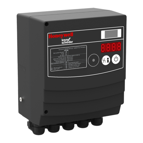
Krom Schroder
Krom Schroder BCU 46 Series User manual
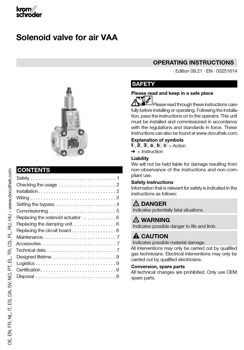
Krom Schroder
Krom Schroder DG 17VC User manual
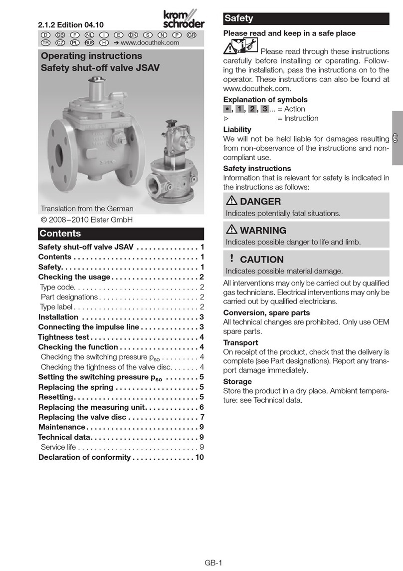
Krom Schroder
Krom Schroder JSAV User manual
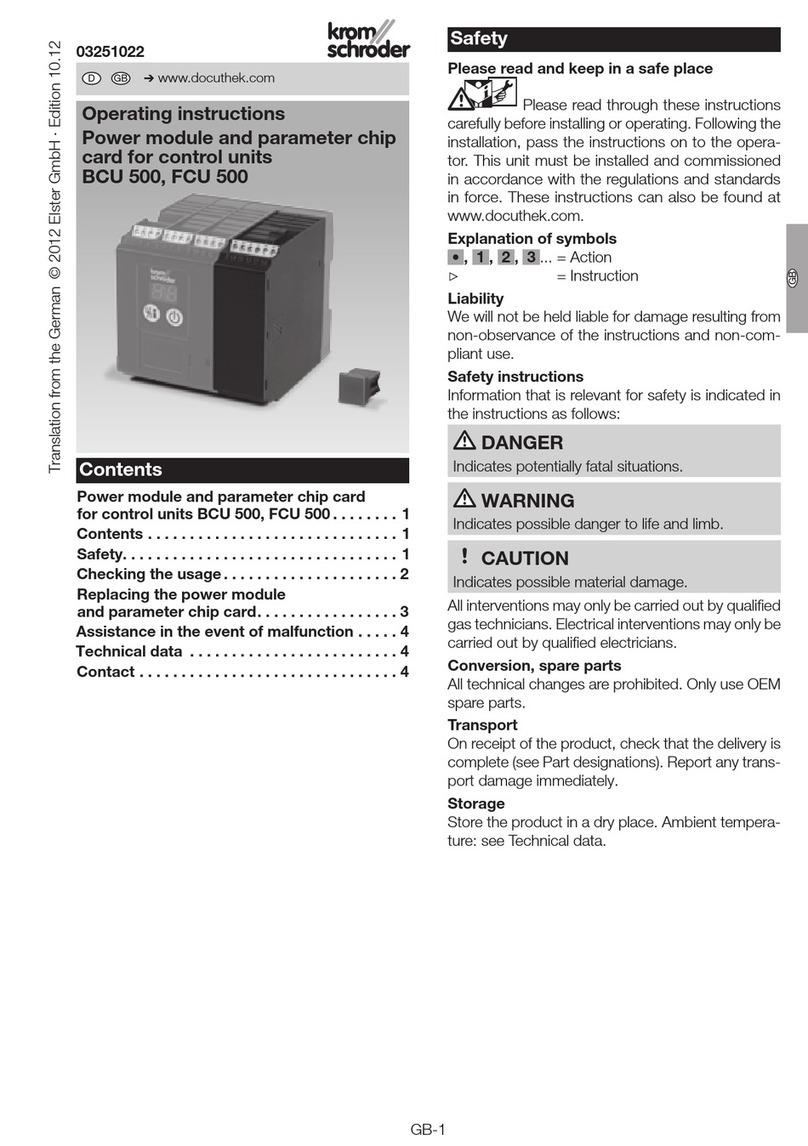
Krom Schroder
Krom Schroder FCU 500 User manual
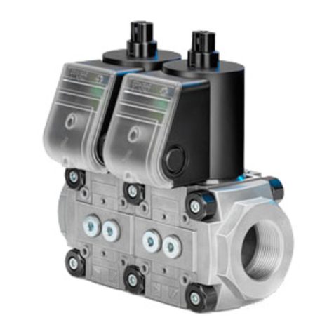
Krom Schroder
Krom Schroder VAS Series User manual
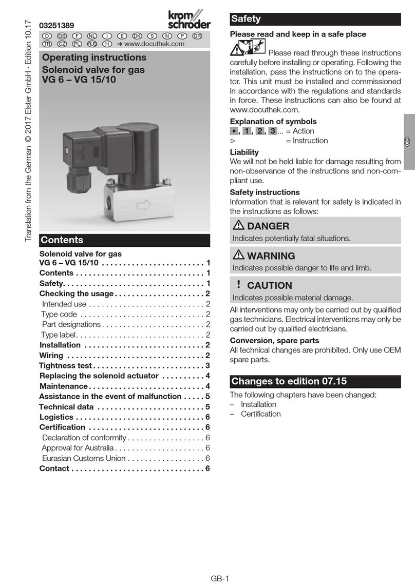
Krom Schroder
Krom Schroder VG Series User manual

Krom Schroder
Krom Schroder BCU 370 User manual
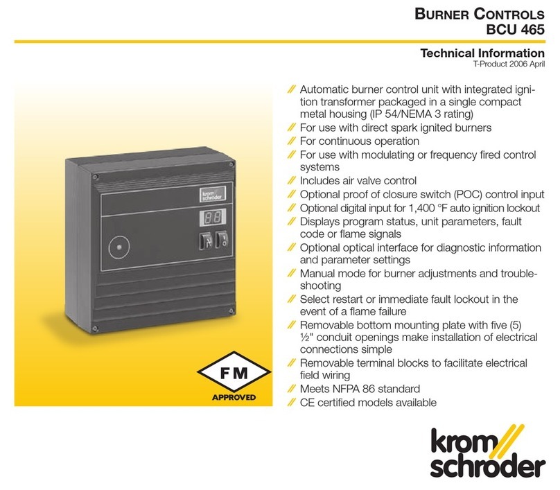
Krom Schroder
Krom Schroder BCU 465 Manual
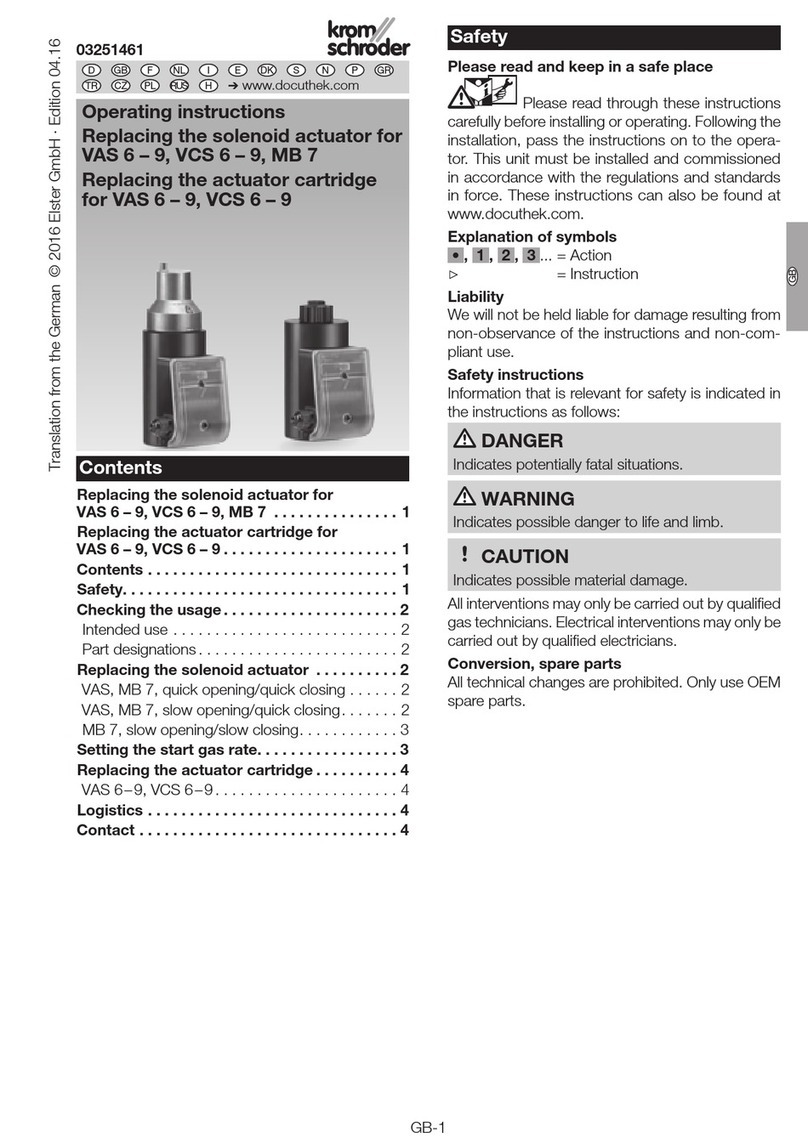
Krom Schroder
Krom Schroder MB 7 User manual
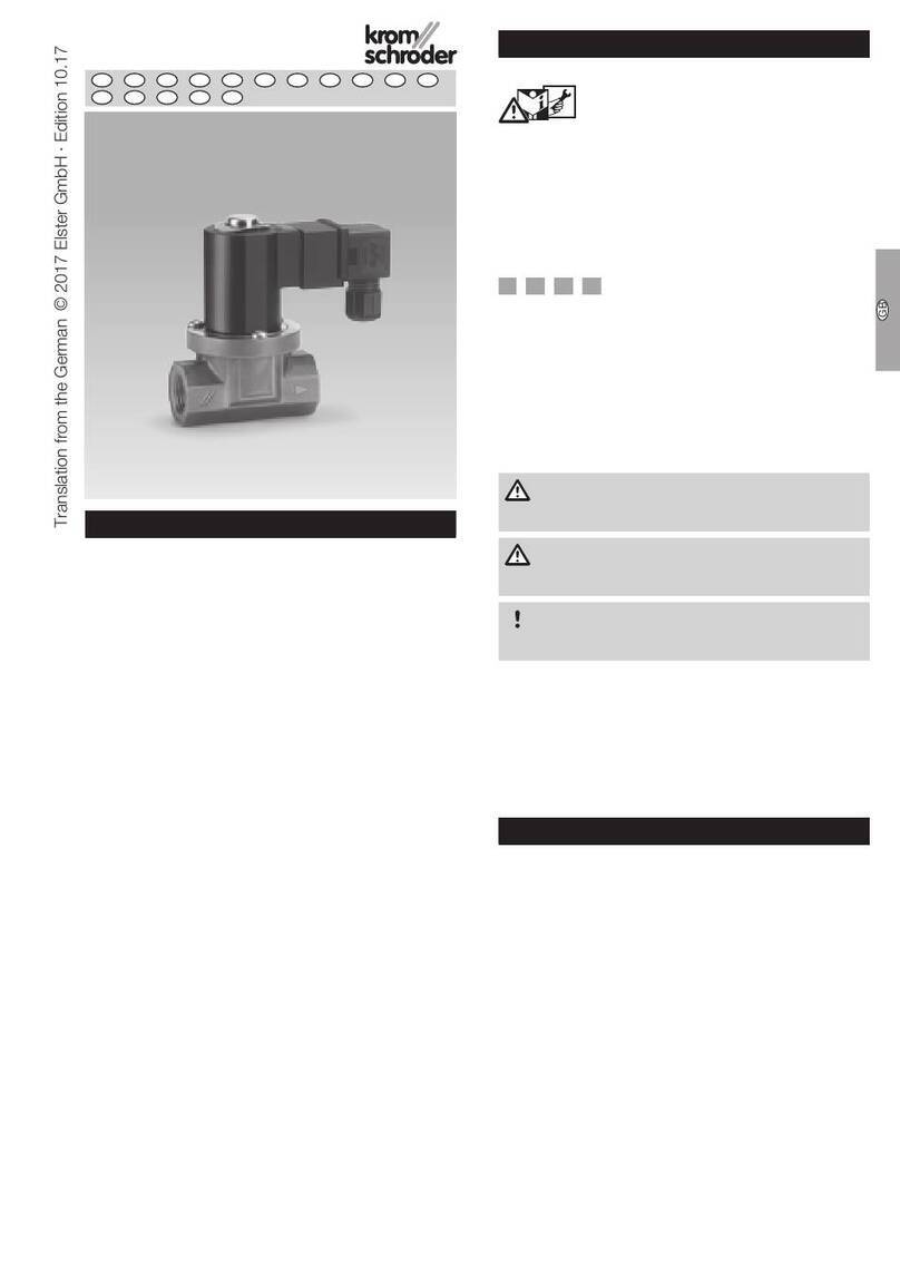
Krom Schroder
Krom Schroder VGP10 User manual
Popular Control Unit manuals by other brands

Festo
Festo Compact Performance CP-FB6-E Brief description

Elo TouchSystems
Elo TouchSystems DMS-SA19P-EXTME Quick installation guide

JS Automation
JS Automation MPC3034A user manual

JAUDT
JAUDT SW GII 6406 Series Translation of the original operating instructions

Spektrum
Spektrum Air Module System manual

BOC Edwards
BOC Edwards Q Series instruction manual

KHADAS
KHADAS BT Magic quick start

Etherma
Etherma eNEXHO-IL Assembly and operating instructions

PMFoundations
PMFoundations Attenuverter Assembly guide

GEA
GEA VARIVENT Operating instruction

Walther Systemtechnik
Walther Systemtechnik VMS-05 Assembly instructions

Altronix
Altronix LINQ8PD Installation and programming manual
