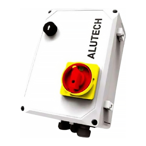
Alutech CUL11 Instruction manual

CONNECTION
AND OPERATIONAL
MANUAL
Control unit
CUL11
English
2020 www.alutech-group.com


INSTALLATION AND OPERATION MANUAL | CUL11 CONTROL UNIT 11
INSTALLATION AND OPERATION MANUAL
CUL11 CONTROL UNIT
Dear customer!
Thank you for purchasing our product. We hope that its quality will conrm that you have
made the right choice.
Due to the constant improvement of construction, ALUTECH Door Systems LLC reserves
the right to change this manual without giving prior notice to customers (buyers).
© 2020 ALUTECH Door Systems
CONTENT
1. General information and safety measures ............................................ 3
2. Product description ......................................................................... 4
3. Technical specications ..................................................................... 5
4. Electric module ................................................................................ 5
5. Operation test and commissioning ..................................................... 8
6. Operation ........................................................................................ 9
7. Faults and recommendations on their elimination ............................... 10
8. Storage, transportation and disposal ................................................. 11
9. Warranty liabilities .......................................................................... 12
10. Commissioning certicate ................................................................ 13
11. Record of repairs and maintenance while under warranty ..................... 14


INSTALLATION AND OPERATION MANUAL | CUL11 CONTROL UNIT 33
GENERAL INFORMATION AND SAFETY MEASURES
1. GENERAL INFORMATION AND SAFETY MEASURES
YThis manual contains important information on safety. Prior to installation, you should
carefully read all information provided below. Keep this manual for further use.
Do not start installing or operating the product if you have any questions or something is notclear.
Contact the local service department or ALUTECH oce, if necessary.
Observe the safety measures established by the current regulations and this manual. While
performing works, you must strictly follow the safety regulations.
Installation, connections, nal tests, commissioning, technical maintenance and repair (trouble-
shooting) must be performed by qualied and trained personnel. Installation, connections,
adjustment and operation of the product in violation of the requirements of this manual are
not allowed as it can lead to damage, injures and losses.
Modications of any elements of the product construction and non-intended use are not al-
lowed. Manufacturer and supplier are not responsible for any damage caused by unauthorised
modications of the product and non-intended use.
The level of possible risk (hazard) should be assessed. Identify, which auxiliary equipment (ac-
cessories) is required in order to eliminate possible risks and comply with the current safety
regulations.
The product is not designed for use in an acid, salty or explosive environment.The product should
be at a sucient distance away from heat source and open re. Failure to comply with this require-
ment can lead to product damage, cause its malfunction, re and other hazardous situations.
When installing and operating, there should be no foreign objects or liquids inside the product
otherwise disconnect the product from mains supply and contact the service department. Op-
erating the product in this state is unsafe. The control unit is to be installed with cable glands
downward to avoid water penetration.
When performing any works (installation, repair, maintenance, cleaning and other) and con-
nections inside the product, switch the power o. If the switching unit is located beyond eld
of view, attach the sign ‘Do not switch on. Men at work’ and take measures to eliminate the
possibility of unauthorised voltage supply.
Observe safety measures while using power cable (power cord):
• completely insert the plug into the socket (if any);
• do not pull the cord itself while withdrawing the plug from the socket;
• do not use a socket with poor contacts;
• do not touch the plug with wet hands;
• do not damage the power cord, do not twist the cord, do not bend the cord sharply and
do not stretch;
• do not place heavy objects on the power cord and do not place it near hot objects;
• ensure easy access to the socket;
• use only the power cord supplied;
• do not use a power cord that is damaged or has defects.
In order to connect power supply it is recommended to use the plug of 015 3 P+N+E 16A/6h
type and the socket of corresponding type.
The place of product installation should be protected against impacts and the surface should
be adequately strong. The control unit should be placed within sight of equipment at a height
of not less than 1.5 m. Electric mains should be equipped with a protective earthing. Ensure that
the design and connection of the earthing system are correct.

INSTALLATION AND OPERATION MANUAL | CUL11 CONTROL UNIT44
PRODUCT DESCRIPTION
The section of electric mains to which the product is connected should be equipped with a pro-
tection device (three-pole circuit-breaker). The distance between terminals in the protective
cutout device should be at least 3 mm.
Parameters of electric cables used (section, number of wires, length and other) should comply
with the connection diagram, device power, laying distance, laying method, ambient conditions.
Use a multicore cable with double insulation.
Electric cables should be protected against contact with any rough and sharp surfaces, use
corrugated tubes and cable glands for laying cables.
The company reserves the right to change this manual and product construction without prior
notice, however maintaining the same functionality and purpose.
Instruments and materials used should be complete, in good condition and comply with the
current safety regulations, standards and instructions.
The company does not directly control the installation of the product and automation devices,
its maintenance and operation, and cannot be responsible for the safety of product installation,
operation and technical maintenance.
Recommendations described in this manual should be considered as an example, as the place
of installation can dier. The task of the installer is to make the most appropriate decision.
The installer is responsible for work on the entire system. In his work, he should observe the cur-
rent regulations and standards (e.g., DIN 1986, EN12050, EN1398). He is also responsible for main-
tenance of technical documentation of the entire system that is supplied with the equipment.
The content of this manual cannot be used as grounds for legal challenges.
2. PRODUCT DESCRIPTION
The unit is designed to control components of the transfer equipment. Directly for the transfer
platform with telescopic (extensible) ramp equipped with 2-valve hydraulic unit. On-o switch 1
(g. 1), control buttons 2 and 3, indication LED 4 are located on the cover of control unit housing.
The control unit is supplied with a cable 5G 1.5sq.mm for power connection (1 m long/without
plug). When being manufactured, the dock levellers are tted with 4G 1 sq.mm cable for con-
nection of the electric motor for the hydraulic unit and two 2×1sq.mm cables with connectors
for connection of hydraulic unit valves. The Manufacturer chooses the necessary length of the
cables depending on the size of a dock leveller. The set of cables СTL07-2 consists of 7 m long
cables. The set of cables СTL10-2 consists of 10 m long cables.
190
280
254
190
239
180
165
120
1
4
2
3
Figure 1. Control unit (dimensions are given in millimeters)

INSTALLATION AND OPERATION MANUAL | CUL11 CONTROL UNIT 55
TECHNICAL SPECIFICATIONS
3. TECHNICAL SPECIFICATIONS
Parameter nameParameter name ValueValue
Supply voltage 3~400 V±10%
Supply frequency, Hz 50
Electric motor power, kW ≤1.5
Power demand in standby, W ≤5
Valve rated supply voltage 24 V DC
Valve rated power, W 18
Auxiliary equipment power supply
(optical door position sensor) 24 V DC/max. 100 mA
Light lamp power supply 230 V/max. 100 W
Section of wires to be connected to connectors, mm2max. 2.5
IP degree of protection IP54 (professional installation)
Operating temperature range, ºС –25…+40
Overall dimensions, mm 190×280×145
4. ELECTRIC MODULE
The electric module to which other devices are connected (g. 2) is located inside the control unit.
List of module elements
ElementElement DescriptionDescription
FU1
T10А500V fuses
CAUTION! Use quartz-sand-lled fuses
FU2
FU3
FU4 T2А500V fuse
CAUTION! Use quartz-sand-lled fuse
FU5
T3.15А250V fuses
FU6
FU7
HL1 LED indicating the operation of control buttons 2and 3(g. 1). Lights up when
the control button is pressed
HL2 LED indicating the electric motor overcurrent in hydraulic unit. Lights up when
the overcurrent protection is triggered
HL3 LED indicating the connection of hydraulic unit valves. Lights up when valves are not
connected to VAL1 and VAL2 outputs (or to one of the outputs)
HL4 LED indicating the state of door position sensor. Lights up when the sensor is activated
HL5 LED indicating the operation of valve connected to VAL1 output. Lights up when the
valve is not connected to VAL1 output or voltage is supplied to the valve

INSTALLATION AND OPERATION MANUAL | CUL11 CONTROL UNIT66
ELECTRIC MODULE
ElementElement DescriptionDescription
HL6 LED indicating the operation of valve connected to VAL2 output. Lights up when the
valve is not connected to VAL2 output or voltage is supplied to the valve
HL7 LED always lights up, VAL3 output is not used for CUL11 unit
J1 Connector for power supply connection (g. 3)
J2 Connectors for on-o switch 1 connection (g. 1, g. 3).
CAUTION! The switch is designed to turn on and turn o the voltage supplied
to the unit. Do not turn o during operation, wait until the end of the
leveller nishes its working cycle
J6
J3 Connector for protective earthing (PE) connection
J4
Connector for light lamp connection 230 V/max. 100 W (g. 4).
The lamp lights when the unit has performed any rst action (control button is
pressed, door position sensor is activated) and goes out when the power is turned
o. If faults in the platform operation are detected, the lamp no longer lights
(section7 ‘Faults and recommendations on their elimination’)
J5
Connector for connection of the electric motor of hydraulic unit (g. 5) and STOP safety
sensor (NC).
CAUTION! While opening the jumper+24 V at J5 connector, control voltage of
24 V DC turns o and control unit does not operate. For control unit
operation, OUT+24 V and IN+24 V contacts should be closed (NC)
J8
Connector for connection of hydraulic unit valves (g. 6) and door position sensor (g. 8).
If the sensor is triggered, the electric motor of hydraulic unit turns o and the dock
leveller starts lowering
J9 Connector for connection of the jumper to select an output type of door position sensor:
PNP or NPN (terminal output)
J10 Connector for connection of control buttons 2and 3, LED 4(g. 1, g. 7)
J12
The jumper for setting the overcurrent protection in the electric motor of hydraulic
unit. In the case of overcurrent or fault ( section 7‘Faults and recommendations on their
elimination’), the dock leveller movement completely stops (STOP).
CAUTION! If the jumper is not set, the protection will be turned o
J13
Connector for connection of the jumper to select a contact type of door position sensor:
NO (normally open) or NC (normally closed).
CAUTION! If the door position sensor is not connected, the jumper should be
connected to NO contact
YATTENTION! The position of the jumper set in J12 and J13 connectors is saved when the
on-o switch 1 (g. 1) is switched from ‘0’ position (‘O’ position) to ‘I’ position (‘On’ position)
and maintained during the control unit operation. If the jumper position in J12 and J13
connectors is required to be changed, power o the unit, set the jumper in the appropriate
position and power on the unit.

INSTALLATION AND OPERATION MANUAL | CUL11 CONTROL UNIT 77
ELECTRIC MODULE
J3 J1
J2
HPT-OUT
N L3 L2 L1
PE PE
HPT-IN
J6
3~ 400V
J4
N
LL
LAMP
FU7
FU6
FU5
3×T3.15A250V
FU3 FU1
FU2
3×T10A500V
+24V
KEY4
LED+
+24V
+24V
KEY2
+24V
KEY3
KEY1
J10
VAL2
VAL1
+24V
GND
GND
GND
VAL3
DAT
J8
HL7
HL6
HL5
HL4
2,6A
3,2A
3,8A
4,4A
5A
5,6A
6,2A
6,8A
7,4A
8A
8,6A
9,2A
J12
J5
WVU
MOTOR
IN
OUT
+24V
LED-
J13
HL1 HL2 HL3
NC
NO
PNP
NPN
J9
T2A500V
FU4
HPT-OUT
J2
J1
J6 HPT-IN
N L3 L2 L1
PE PE
J3
BU
GY
BK
BN
1
3
5
2
4
6
YE-GN
Figure 2. Electronic module
J3 J1
J2
HPT-OUT
N L3 L2 L1
PE PE
HPT-IN
J6
3~ 400V
J4
N
LL
LAMP
FU7
FU6
FU5
3×T3.15A250V
FU3 FU1
FU2
3×T10A500V
+24V
KEY4
LED+
+24V
+24V
KEY2
+24V
KEY3
KEY1
J10
VAL2
VAL1
+24V
GND
GND
GND
VAL3
DAT
J8
HL7
HL6
HL5
HL4
2,6A
3,2A
3,8A
4,4A
5A
5,6A
6,2A
6,8A
7,4A
8A
8,6A
9,2A
J12
J5
WVU
MOTOR
IN
OUT
+24V
LED-
J13
HL1 HL2 HL3
NC
NO
PNP
NPN
J9
T2A500V
FU4
HPT-OUT
J2
J1
J6 HPT-IN
N L3 L2 L1
PE PE
J3
BU
GY
BK
BN
1
3
5
2
4
6
YE-GN
Figure 3. Connection of power supply and on-o switch
Explanation of wire colours used in gures:
BU—blue, BK—black, BN—brown,
GY—grey, YE-GN—yellow-green, RD—red.

INSTALLATION AND OPERATION MANUAL | CUL11 CONTROL UNIT88
OPERATION TEST AND COMMISSIONING
J4
N
L
L
LAMP
230V
max100
W
J5
J3
WVU PE PE
M
3~
YE-GN
IN
OU
T
+24V
V
AL2
V
AL1
+24
GND
GND
GND
V
AL3
DAT
J8
V1
V2
+
24V
KEY4
L
ED+
+
24V
+
24V
KEY2
+
24V
KEY3
KEY1
LED-
N
O
N
O
RD
BU
J10
V
AL2
V
AL1
+24
GND
GND
GND
V
AL3
DAT
J8
-
PNP NC
BN
BK
BU
PNP
NPN
J9
NO
NC
J13
VAL2
VAL1
+24
GND
GND
GND
VAL3
DAT
J8
NC
PNP
NPN
J9
NO
NC
J13
VAL2
VAL1
+24
GND
GND
GND
VAL3
DAT NC
PNP
NPN
J
9
NO
NC
J13
A B C
Figure 4. Lamp connection Figure 5. Electric motor connection
J4
N
L
L
LAMP
230V
max100
W
J5
J3
WVU PE PE
M
3~
YE-GN
IN
OU
T
+24V
V
AL2
V
AL1
+24
GND
GND
GND
V
AL3
DAT
J8
V1
V2
+
24V
KEY4
L
ED+
+
24V
+
24V
KEY2
+
24V
KEY3
KEY1
LED-
N
O
N
O
RD
BU
J10
V
AL2
V
AL1
+24
GND
GND
GND
V
AL3
DAT
J8
-
PNP NC
BN
BK
BU
PNP
NPN
J9
NO
NC
J13
VAL2
VAL1
+24
GND
GND
GND
VAL3
DAT
J8
NC
PNP
NPN
J9
NO
NC
J13
VAL2
VAL1
+24
GND
GND
GND
VAL3
DAT NC
PNP
NPN
J
9
NO
NC
J13
A B C
J4
N
L
L
LAMP
230V
max100
W
J5
J3
WVU PE PE
M
3~
YE-GN
IN
OU
T
+24V
V
AL2
V
AL1
+24
GND
GND
GND
V
AL3
DAT
J8
V1
V2
+
24V
KEY4
L
ED+
+
24V
+
24V
KEY2
+
24V
KEY3
KEY1
LED-
N
O
NO
RD
BU
J10
V
AL2
V
AL1
+24
GND
GND
GND
V
AL3
DAT
J8
-
PNP NC
BN
BK
BU
PNP
NPN
J9
NO
NC
J13
VAL2
VAL1
+24
GND
GND
GND
VAL3
DAT
J8
NC
PNP
NPN
J9
NO
NC
J13
VAL2
VAL1
+24
GND
GND
GND
VAL3
DAT NC
PNP
NPN
J
9
NO
NC
J13
A B C
Figure 6. Valves connection Figure 7. Connection of control
buttons and LED (g.1)
J4
N
L
L
LAMP
230V
max100
W
J5
J3
WVU PE PE
M
3~
YE-GN
IN
OU
T
+24V
V
AL2
V
AL1
+24
GND
GND
GND
V
AL3
DAT
J8
V1
V2
+
24V
KEY4
L
ED+
+
24V
+
24V
KEY2
+
24V
KEY3
KEY1
LED-
N
O
N
O
RD
BU
J10
V
AL2
V
AL1
+24
GND
GND
GND
V
AL3
DAT
J8
-
PNP NC
BN
BK
BU
PNP
NPN
J9
NO
NC
J13
VAL2
VAL1
+24
GND
GND
GND
VAL3
DAT
J8
NC
PNP
NPN
J9
NO
NC
J13
VAL2
VAL1
+24
GND
GND
GND
VAL3
DAT NC
PNP
NPN
J
9
NO
NC
J13
A B C
Figure 8. Connection of the door position sensor:
A—optical sensor, B and C—mechanical sensor
YATTENTION! Examples of connection of the door position sensor located at the door opening
are given in g. 8. The dock leveller is operational (operation is not blocked), when there is
nodoor leaf in the sensor coverage. The door position sensor should be selected and properly
connected depending on sensor type and its installation place (mode of application).
5. OPERATION TEST AND COMMISSIONING
YATTENTION! The initial commissioning should be performed by qualied and trained
personnel to ensure correct operation of the loading equipment. The dock leveller should be
suitable for automation. When installation and electric connection are completed, check that
operations are performed correctly and equipment is ready for operation.

INSTALLATION AND OPERATION MANUAL | CUL11 CONTROL UNIT 99
OPERATION
1. In order to apply the supply voltage to the control unit module, shift the on-o switch 1
(g. 1) to Iposition (‘ON’ position).
If LED 4 (g. 1) does not light up or ashes after switching on the control unit,
see section 7 ‘Faults and recommendations on their elimination’.
2. Make sure/check that HL5 and HL6 LEDs do not light up.
If HL5 and HL6 LEDs or one of them lights up, HL3 LED lights up, then hydraulic
unit valves are not connected or failed.
3. Make sure/check that HL4 LED does not light up, when doors are opened.
If HL4 LED lights up, the door position sensor is triggered (door is closed) or the
jumper position is wrong in J13 connector (g. 2). If the door position sensor is
notused, the jumper should be connected to the NO contact.
4. Carry out the complete work cycle of the dock leveller (section 6 ‘Operation’).
If the leveller does not start operating, starts operating incorrectly or a fault
occurs during operation (HL2 LED lights up), then stop the operation and go to
section 7 ‘Faults and recommendations on their elimination’.
5. If the light lamp is connected to the control unit, check whether the lamp isoperational.
The lamp switches on when the unit has performed any rst action (controlbutton is
pressed, door position sensor is activated) and switches o when thepower is turned o.
If the lamp does not light up, then it is not connected or has failed. If the lamp
stops lighting during platform operation, the fault is detected (section7 ‘Faults
and recommendations on their elimination’).
6. After successful completion of trial cycles, the leveller should return to the initial position.
In order to turn o the power supply, turn the on-o switch 1 (g. 1) in ‘0’ position
(‘OFF’ position).
Operation logic of the control unit for the electric motor and valves
OperationOperation MotorMotor
(MOTOR)(MOTOR) Valve VAL1Valve VAL1 Valve VAL2Valve VAL2
Power on OFF OFF OFF
Lifting of the dock leveller ON OFF ON
Lowering of the dock leveller OFF ON OFF
Lip extension ON OFF OFF
Lip retraction ON OFF ON
Standby mode after leveller lowering (oating position) OFF ON OFF
Door position sensor triggering OFF ON OFF
Stop if a fault is detected (STOP) OFF OFF OFF
OFF—turned o/power o
ON—turned on/power on
6. OPERATION
YATTENTION! Any person (operator), who operates the loading equipment should be aware of
the safety regulations, existing hazards and risks. The product should not be used by children
or people with physical, sensory or mental disabilities, as well as people with poor experience
and knowledge. Before starting to operate the leveller, make sure that there are no people in

INSTALLATION AND OPERATION MANUAL | CUL11 CONTROL UNIT1010
FAULTS AND RECOMMENDATIONS ON THEIR ELIMINATION
the working area. While operating the leveller, monitor all movements of the leveller. Never
touch moving parts of the leveller. No one should be in the working area of leveller.
Turn the on-o switch 1 (g. 1) to the Iposition (‘ON’ position) to apply the supply voltage to
the control unit module.
Loading platform control:
• press and hold control button 2( fig. 1) to lift the platform. When lifting is completed,
release button and the platform will stop.
• after releasing button press and hold button 3(fig. 1) for 2 seconds.
The lip will extend.
Control of button will be allowed only after control of button for more than
2 seconds. If button is pressed after more than 2 seconds since releasing
button, the platform will start lowering automatically. In this case press button
again for at least 2 seconds for the ramp to restart extension.
button running time (holding)—60 seconds.
button running time (holding)—40 seconds.
• after the required lip extension, depress button and after 2 seconds dock leveller
starts automatically lowering in the intermediate position to the vehicle loading level
(floating position—platform follows the movements of vehicle floor).
Returning the leveller to the initial position:
• in order to return the leveller to the initial position press and hold control button 2
(fig. 1) until the leveller lifts and the lip returns into the initial position (retracts back).
• release button and after 2 seconds the leveller automatically lowers into the initial
position.
• switch the on-off switch 1(fig. 1) to ‘0’ position (‘OFF’ position).
The scheduled maintenance of the control unit should be performed as a part of loading equip-
ment service works in strict compliance with the current regulations.
7. FAULTS AND RECOMMENDATIONS ON THEIR
ELIMINATION
FaultFault Possible causePossible cause RecommendationsRecommendations
After turning the
switch 1(g. 1) into
I position, LED 4
doesnot light up
No supply voltage
Check the mains voltage. Make sure that the
control unit is connected to the mains (section4
‘Electric module’). Make sure and replace, if
necessary, the fuses. Check that the jumper is
set at OUT +24 V and IN +24 V contacts of J5
connector. Check that LED 4 is connected
After turning the
switch 1in Iposition,
LED 4 ashes rapidly
Incorrect mains
connection or low
supply voltage
Check the mains voltage. Check that all wires
of power cable are connected to the unit (no
broken wires). Switch wires for power cable
connection, for example, at L1 and L2 contacts
of J1 connector (ensure the correct phase
sequence)
After turning the
switch 1in Iposition,
LED 4 ashes rarely. HL3
LED lights up
No connection
of valves (valve)
Ensure that valves of the hydraulic unit are
connected

INSTALLATION AND OPERATION MANUAL | CUL11 CONTROL UNIT 1111
STORAGE, TRANSPORTATION AND DISPOSAL
FaultFault Possible causePossible cause RecommendationsRecommendations
After pressing
button, the leveller
doesnot lift, LED 4 starts
ashing rarely. HL2 LED
lights up
Electric motor
is not connected
or connected
incorrectly
Make sure the electric motor connections are
correct. Ensure that all cable wires are connected
in J5 connector of the unit and contacts of the
electric motor
The operation of the
dock leveller stops and
LED 4 ashes rarely. HL2
LED lights up. Light
lamp (if connected)
goes dim
Overload protection
in electric motor
is triggered
Set the jumper of J12 connector in the required
current value (section4 'Electronic module').
Check connection of the electric motor
After pressing
button, the leveller
doesnot lift, the sound
of the motor operation
is heard
Incorrect
connection
of electric motor
Switch wires for electric motor connection, for
example, at Wand Vcontacts of J5 connector
After pressing
button, the leveller
doesnot lift, but the
ramp starts extending
Incorrect
connection
of valves
Correctly connect valves to VAL1 and VAL2
contacts of J8 connector according to the
operation logic (see table on page 11)
After pressing
button, the dock leveller
doesnot lift or stops
while moving and
automatically lowers.
HL4 LED lights up
Door position
sensor is triggered
If the door position sensor is connected, check
whether the door is open. Make sure that the
sensor is connected and operational (check the
state change of sensor LED—LED goes dim or
lights up when the sensor is triggered). Check
the setting of jumpers in J9 and J13 connectors
When pressing
or button, HL1
LED doesnot light
up, the dock leveller
doesnotmove
Control buttons
arenot connected
or failed
Make sure that control buttons are connected
and operational. Make sure that there is noother
fault (check the indication of other LEDs), which
blocks the control button operation
YATTENTION! In the normal operation mode, LED 4 (g. 1) constantly lights up. If after
powering on the unit LED 4 ashes rapidly or rarely, then the control unit operation is blocked.
If the fault occurs during the operation of the dock leveller, the dock leveller movement stops
(no oating position) and control unit operation is blocked. If the light lamp is connected, it
goes dim.
YATTENTION! In order to restore the control unit operation after elimination of the fault, it is
necessary to power on the unit (on-o switch) and briey press button to lift the leveller.
In case there is a fault that can’t be eliminated with the help of this manual, please contact
the service department. To get more information about it, contact the supplier (dealer or the
company that carried out the installation).
8. STORAGE, TRANSPORTATION AND DISPOSAL
The product should be stored in its packaging in closed, dry places. Donot expose to atmos-
pheric precipitation and direct sunlight. Storage period—3 years from the date of manufacture.

INSTALLATION AND OPERATION MANUAL | CUL11 CONTROL UNIT1212
WARRANTY LIABILITIES
Transportation may be carried out by means of any roofed land vehicle providing crush and
disposition protection inside it.
Disposal is carried out according to the current waste processing and disposal regulations
applicable in the country of the Customer. The product doesnot contain precious metals
and substances that pose hazard to life, people’s health and environment.
9. WARRANTY LIABILITIES
1. Normal operation of the product is guaranteed while meeting the rules of its storage,
transportation, adjustment, operation; while performing installation and technical
maintenance (timely and adequate) by the organisation specialised in automation
systems and authorised to perform installation and technical maintenance.
2. Warranty period is ________________ and starts from the date of delivery of the product
to the Customer or from the date of manufacture, if the date of delivery is unknown.
3. Manufacturing faults that occur during the warranty period are eliminated by the service
department that performs warranty maintenance.
Note: parts replaced under the warranty become the property of the service department that
performed the product repair.
4. Warranty on the product is not valid in the following cases:
• violation of rules of storage, transportation, operation and product installation;
• installation, adjustment, repair, reset or modification of the product by persons
unauthorised to perform these works;
• damage of the product caused by the instability of supply line or non-compliance of
mains supply parameters with the values, established by the Manufacturer;
• damage of the product caused by water penetration;
• force majeure (fire, lightning stroke, floods, earthquakes and other natural disasters);
• damage of the product construction caused by the Customer or third party;
• faults and defects caused by the absence of scheduled technical maintenance and
inspection of the product;
• failure to provide a completed (filled-in) manual.

INSTALLATION AND OPERATION MANUAL | CUL11 CONTROL UNIT 1313
COMMISSIONING CERTIFICATE
10. COMMISSIONING CERTIFICATE
Serial number and date of manufacture_____________________________________________
data from the product label
Information about organisation authorised to perform installation and technical maintenance
______________________________________________________________________________
______________________________________________________________________________
name, address and phone
Date of installation: ________________________________________
L.S. day, month, year
Signature of the person
responsible for the installation_______________________________
signature
________________________________________________________
print name
Consumer (Customer) has veried the completion, agreed and accepted warranty conditions
and terms and has no claims against the product appearance. The product is installed and ad-
justed in accordance with the established requirements and qualied for operation. Consumer
has been provided with information on existing hazards and risks, as well as rules on operation.
Information about customer (consumer) ____________________________________________
______________________________________________________________________________
name, address and phone
Signature of customer (consumer) _____________________
signature
_________________________________________________
print name

INSTALLATION AND OPERATION MANUAL | CUL11 CONTROL UNIT1414
RECORD OF REPAIRS AND MAINTENANCE WHILE UNDER WARRANTY
11. RECORD OF REPAIRS AND MAINTENANCE
WHILE UNDER WARRANTY
Repair contractor information_____________________________________________________
Repair operations list ____________________________________________________________
______________________________________________________________________________
______________________________________________________________________________
Date of repair __________________________________________________________________
Signature of the person
L.S. responsible for the repair ____________________________
signature
_________________________________________________
print name
- - - - - - - - - - - - - - - - - - - - - - - - - - - - - - - - - - - - - -
Repair contractor information_____________________________________________________
Repair operations list ____________________________________________________________
______________________________________________________________________________
______________________________________________________________________________
Date of repair __________________________________________________________________
Signature of the person
L.S. responsible for the repair ____________________________
signature
_________________________________________________
print name

INSTALLATION AND OPERATION MANUAL | CUL11 CONTROL UNIT 1515
SPECIAL NOTES
______________________________________________________________________________
______________________________________________________________________________
______________________________________________________________________________
______________________________________________________________________________
______________________________________________________________________________
______________________________________________________________________________
______________________________________________________________________________
______________________________________________________________________________
______________________________________________________________________________
______________________________________________________________________________
______________________________________________________________________________
______________________________________________________________________________
______________________________________________________________________________
______________________________________________________________________________
______________________________________________________________________________
______________________________________________________________________________
______________________________________________________________________________
______________________________________________________________________________
______________________________________________________________________________
______________________________________________________________________________
______________________________________________________________________________
______________________________________________________________________________
______________________________________________________________________________
______________________________________________________________________________
______________________________________________________________________________
______________________________________________________________________________
______________________________________________________________________________
______________________________________________________________________________


Арт. R7090139
04.2019
10, Selitskogo str.
220075, Minsk, Republic of Belarus
Tel. +375 (17) 330 11 00
Fax +375 (17) 330 11 01
www.alutech-group.com
Table of contents
Other Alutech Control Unit manuals
Popular Control Unit manuals by other brands

ZIEHL-ABEGG
ZIEHL-ABEGG UNIcon CTG-150AV operating instructions

NI
NI SCC-CO20 user guide

Bosch
Bosch ISM 1 installation instructions

SCHUNK
SCHUNK PCFC Assembly and operating manual

Cobalt Digital Inc
Cobalt Digital Inc BBG-1040-ACO product manual

Moxa Technologies
Moxa Technologies MiiNePort W1 Series user manual