BIC · Edition 09.22
EN-7
odourless and poisonous! Conduct a flue gas
analysis.
– The burner must only be commissioned by
authorized trained personnel.
➔If the burner does not ignite even though the auto-
matic burner control unit has been switched on and
off several times: check the entire system.
➔After ignition, monitor the flame and the gas and
air pressure measured on the burner. Measure the
ionization current. Switch-off threshold– see au-
tomatic burner control unit operating instructions.
+μA –
Z
➔
The burner must only be ignited at low-fire rate
(between 10 and 40% of the rated capacityQmax)–
see type label.
5.2 Determining the gas and combustion air
flow rates
➔Qgas: Gas flow rate in m3/h (ft3/h)
➔PB: Burner capacity in kW (BTU/h)
➔Hi: Gas heating value in kWh/m3(BTU/ft3)
➔Qair: Air flow rate in m3(n)/h (SCFH)
➔ λ: Lambda, air index
➔
Lmin: Minimum air requirement in m3(n)/m3(n) (SCF/
SCF)
➔
Information on the gas quality supplied can be
obtained from the gas supply company.
Common gas qualities
Gas type Heating value
HuHoLmin
kWh/
m3(n)
BTU/
SCF
m3(n)/
m3(n)
(SCF/
SCF)
Natural gas H 11.0 1114 10.6
Natural gas L 8.9 901 8.6
Propane 25.9 2568 24.4
Low calorific
value gas 1.7–3 161–
290 1.3–2.5
Butane 34.4 3406 32.3
➔
Data in kWh/m
3
(n) refer to the lower heating val
-
ueH
u
and data in BTU/SCF refer to the higher
heating valueHo(gross calorific value).
➔
A minimum air excess of 20% (lambda=1.2) should
be set in a cold furnace for initial adjustment since
the air volume falls as the temperature rises.
➔
Fine adjustment should be carried out at max.
furnace temperature and at as high a capacity
demand as possible.
5.3 Notes on the flow rate curve
➔
If the gas density in the operating state differs from
that reflected in the flow rate curve, convert the
pressures according to the local operating state.
pB = pM .
B
➔
δM: Gas density reflected in the flow rate curve
in kg/m3(lb/ft3)
➔ δB: Gas density in operating state in kg/m3(lb/ft3)
➔pM: Gas pressure reflected in the flow rate curve
➔pB: Gas pressure in operating state
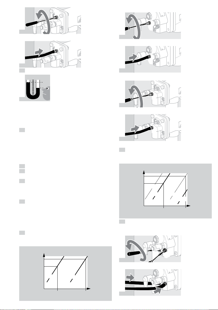
5.4 Burners without gas measuring orifice
1 Read the gas pressure pgas and air pressure pair
from the enclosed flow rate curve for cold air on
the basis of the calculated flow ratesQ.
[mbar (inch WC)]
[m3/h (ft3/h)]
pgas pair
pair
pgas
Qair
Qgas
➔
Note possible capacity changes due to positive
or negative pressures in the furnace/combustion
chamber. Add positive pressures or subtract neg-
ative pressures.
➔As not all the effects caused by the equipment are
known, setting the burner using the pressure values
is only approximate. It is possible to set the burner
precisely by measuring the flow rates or flue gas.
5.5 Burners with gas measuring orifice
1 Read the differential pressureΔpgas and air pres-
surep
air
from the flow rate curve for cold air on the
basis of the calculated flow rates.
[mbar (inch WC)]
[m3/h (ft3/h)]
Δpgas pair
pair
pgas
Qair
Qgas
pgas
∆pair
➔Note possible capacity changes (air) due to pres-
sure loss in the furnace/combustion chamber. Add
positive pressures or subtract negative pressures.
➔
The differential gas pressure Δp
gas
measured on
the integrated gas measuring orifice is independent
of the furnace chamber pressure.