KSH International BS-101 User manual

Bluetooth to RS-232&RS422/485
BS-101 Bluetooth Adapter
Operation Manual
Version: 201912a

1
1
1
INTRODUCTION .................................................................................................... 2
2
2
PACKAGE CHECKLIST ......................................................................................... 3
3
3
PRODUCT SPECIFICATIONS ............................................................................... 4
4
4
PRODUCT PANEL VIEWS DESCRIPTIONS ......................................................... 6
ANTENNA CONNECTOR .............................................................................................. 7
SERIAL I/O PORT ...................................................................................................... 7
TERMINAL RESISTOR ................................................................................................. 8
LED INDICATORS ...................................................................................................... 8
5
5
HARDWARE INSTALLATION ................................................................................. 9
6
6
CONFIG TOOL INSTALLATION & SETUP ........................................................... 10
TOOL INSTALLATION ....................................................................................... 10
BT RS232 CONFIG TOOL PARAMETERS CONFIGURATION ................................... 11
A
AP
PP
PE
EN
ND
DI
IX
X
A
A ........................................................................................................... 16

2
1
1
Introduction
Thank you for your purchase of BS-101 as the Bluetooth To Serial Adapter. Featuring
Bluetooth wireless technology, it is for replacement of standard RS232 or industrial
RS422/485 cable perfectly, with standard RS232 and industrial RS422/485 interfaces,
so can be easily adopted for industrial machines with RS232 or RS422/485 interfaces.
BS-101 is compatible with all Bluetooth V2.1-certified and is backward compatible
with v1.1/1.2 devices. You can connect between your computers (Master) and
RS232/422/485 devices (Slave) 100 meters away without cables in your working
environments.
Security of Bluetooth wireless communication is very strong because it uses the
frequency hopping and 128bit encryption in 2.4Ghz frequency range. Hardware
setting is very easy and simple. The maintenance is very convenience too. One pair
of BS-101 will try to connect automatically whenever powered up after finishing the
device’s parameters configured. It does not require extra software for operation. No
installation of driver and application software.

3
2
2
Package checklist
BS-101 product is shipped with the following items:
1 unit of BS-101 Bluetooth to RS232 / 422 / 485 converter
1 unit of Power Adaptor (9V DC, 200mA) is option
User Operation Manual
Software CD
NOTE: Notify your sales representative if any of the above items is missing or
damaged

4
3
3
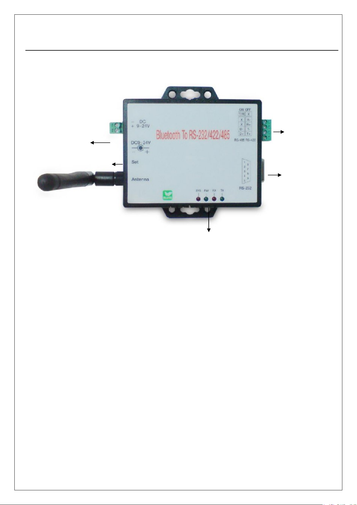
Product Specifications
Features:
● Support Bluetooth 2.1
● Maximum packet size 250 bytes
● Transmission range up to 100 Meters.
● Built in 15KV ESD protection for signals
● RS-422/485 surge protection
● Bluetooth Windows Configuration Utility
● Not apply to Modbus protocol.
Serial Port
● No. of Ports : RS-232 / 422 / 485 * 1 Port
● Port Type : DB9 Female RX/TX crossover
● Built-in RS-422/RS-485 Terminal Resister (Surge Protection)
● Speed : 1200 bps〜115.2 K bps
● Parity : None , Odd , Even
● Data Bit : 8
● Stop Bit : 1 , 2
● Flow Control : DTR / DSR
● RS-232 Signals : Rx , Tx , GND , RTS , CTS
● RS-422 Signals : Rx+ , Rx- , Tx+ , Tx- (Full-duplex)
● RS-485 Signals : Data+ , Data- (Half-duplex)
● Connected Serial port type identification : Auto-Detection
● 15KV ESD for all signal
Bluetooth I/O Port
● No. of Ports :Bluetooth * 1 Port
● Compliant with Bluetooth v2.1+EDR
● Support Bluetooth Serial port profile(SPP)
● Operate in 2.4GHz – 2.483GHz ISM Band

5
● Support Bluetooth Radio with Class 1 RF
● Tx Output Power : 13 dBm (max)
● Rx Sensitivity : -86 dBm (min)
● SPP : Support (Serial Port Profile)
● Operating Distance up to 100 Meters
Power : 9V DC / 200mA, Consumption 150mA
Led Lamp :
SYS (red), Pair (green), Rx (red), Tx (green)
Environment : Operating : -10°C ~ 70°C (14°F ~ 158°F)
Storage : -20°C ~ 80°C (-4°F ~ 176°F)
Dimension : 110 * 90 * 26 mm ( W * D * H )
Weight : 95 ± 5gm
Regulatory Approvals :
● EMC : FCC Class A, CE Class A
● WARRANTY : 1 year
● RoHS

6
4
4
Product Panel Views Descriptions
BS-101 Product Views
DC-In Power Outlet
The BS-101 Bluetooth to RS232 / 422 / 485 is powered by a single 9V DC
(Inner positive/outer negative) power supply and 200mA of current. A suitable
power supply adapter is part of the package. Connect the power line to the
power outlet beside of antenna connector and put the adapter into the socket.
If the power is properly supplied, the red color LED (SYS ) will be on.
DC-In
Power Outlet
Serial I/O Port
RS-232
Sync Button
LED Indicators
Antenna
Serial I/O Port
RS422/485

7
Antenna Connector
The antenna is a standard SMA jack. Simply connect it to a 2.0dBi dipole
antenna (Standard Rubber Duck) and it is 50 Ohms impedance and can
support 2.4GHz frequency.
Serial I/O Port
Connect the serial data cable between the converter and the serial device.
Follow the parameter setup procedures to configure the converter (see the
following chapters).
Serial I/O Port
RS-485/RS-422
Terminal Resistor
Serial I/O Port
RS232
Antenna

8
Terminal Resistor
The purpose is for compensating signal attenuation in long distance
connection at RS-485/RS-422 I/O. If the switch 1 & 2 are set in “ON” position,
the signal compensation will be activated. To disable the function, just to
push switch 1 & 2 to opposite position.
LED Indicators
SYS (Red):
It is the power indicator, when the power is on then the LED will blink once
per second.
Pair (Green):
Before connecting to synchronize between the device and the “BT RS232
Config Tool” software, the green LED will be blinking
After connecting to synchronize between the device and the “BT RS232
Config Tool” software, the green LED (Pair) will be on
RX (Red):
Data received indicator (When data are received from the network, the LED
will be on.)
TX (Green):
Data sent indicator (When data are sent out to the network, the LED will be
on.)

9
5
5
Hardware Installation
1. Connect BS-101 Bluetooth adapter to COM Port of PC and then to connect DC
power adapter and jack into power outlet and DC-in outlet. You will see the red
LED is going to be on and the green LCD will be blink.
2. After running the BT RS232 Config Tool and finish configuration. Click the icon
of “Connect” in tool software and press the set button of BS-101 Bluetooth
adapter immediately.
3. The green LED will be turn into on. The BS-101 Bluetooth adapter is active.

10
6
6
Config Tool Installation & Setup
When setting up BS-101 adapter for the first time, you have to install and run
“BT1.exe” as “BT RS232 config tool” first in your computer device. The utility CD is
enclosed in the device box. Before you use BS-101 adapter, you have to pair it with
another BS-101 device.
All the BS-101 Bluetooth to RS-232&RS422/485 Adapters must be configured first
before you use it. The purpose of configuration is to pair two BS-101 devices for an
exclusive connection between them, and pairing is done by utilizing Bluetooth
address and PIN code
Tool Installation
When setting up BS-101 adapter for the first time, you have to install the
utility software of “BT RS232 config tool” in your computer first which is an
executable program in Windows 32 bit environments. BT RS232 config tool
is used to detect and setup the installed.

11
BT RS232 Config Tool Parameters Configuration
After double click the icon of BT1 as “BT RS232 Config Tool”, the
configuration screen will be pop-up as the above picture.
A. COM Port
Select COM port number, you have to avoid the port conflict with other
device in computer and use available port number
B. Device Name
Select device name is for identify each one device and you can follow
the name by tool access or retyping the new name by yourself.
C. Local Address
Local address will be automatically changed after finishing the
parameter configuration to apply.
D. Peer Address
Peer address is for pairing device to communicate in a same network
address.
E. PIN Code
PIN code is for the purpose of security consideration during as like a
pass key. Device uses this “PIN Code” to identify during connecting

12
and communication.
F. Role
Role is for identifying a role of the device as a master or slave. The
item of “Role” is chose “Master”. The device will be play like a DTE
mode - Data Terminal Equipment (such as a PC). If the item of “Role” is
chose “Slave” and the device will be play like a DCE - Data
Communication Equipment (such as a Modem)
You can setup your BS-101 device as what type of the RS232 device
you are going to connect in DTE or DCE mode to work with it.
G. Discoverable
The item of discoverable is for allowing (or not ) the device is detected
by other Bluetooth devices.
H. Baud Rate
The item of baud rate is for the pack transmission speed. The baud
rate range is from 120 bps〜115.2K bps and depend on transmission
distance and environments. Normally, the parameter of baud rate is sat
around 9600 bps.
I. Handshake(DSR/DTR)
The item of handshake is set at the “Disable” item.
J. Stop Bit
The item of stop bit is set at the “One Bit” item.
K. Parity
The item of parity is set at the “None” item.

13
Apply “Connect”
After finish the parameters configuration, click the icon of “Connect” in BT
RS232 Config Tool screen and meanwhile press the Synchronous button
immediately on the left side of the device. And then the next screen of
parameters configuration is pop-up. The icon of “Connect” is changed to
“Disconnect” and two icons will be turned into active mode on the bottom of the
BT RS232 Config Tool screen.

14
Apply “Write”
To click the item of “Write”, the meaning is to save all parameters after configuring
into the “BT RS232 Config Tool”.

15
Apply “Read”
To click the item of “Read”, the meaning is to load all parameters as last time
saving from the “BT RS232 Config Tool”. The local address will be updated the
real device address at first time.

16
A
Ap
pp
pe
en
nd
di
ix
x
A
A
Pin outs and Connector
□
□
□DC Power outlet
□
□
□RS-232 Pin Assignment
The pin assignment scheme for a 9-pin male connector on a DTE is
given below.
PIN 1 : NC PIN 2 : TXD PIN 3 : RXD PIN 4 : DSR
PIN 5 : GND PIN 6 : DTR PIN 7 : CTS PIN 8 : RTS
PIN 9 : Power ( optional )
□
□
□RS-232 Wiring Diagram
Serial Device BS-101
2 RX 3 TX
3 TX 2 RX
5 GND 5 GND
4 DTR 6 DSR
6 DSR 4 DTR
□
□
□RS-422/485 Pin Assignment
The pin assignment scheme for a 4-pin RS-422 is given below.
1 2 3 4

17
RS-422 : PIN 1 : T+ PIN 2 : T- PIN 3 : R+ PIN 4 : R-
RS-485 : PIN 1 : D+ PIN2 : D-
□
□
□RS-422 Wiring Diagram
Serial Device BS-101
T+ 3 R+
T- 4 R-
R+ 1 T+
R- 2 T-
□
□
□RS-485 Wiring Diagram
Serial Device BS-101
D+ 1 D+
D- 2 D-
Table of contents
Other KSH International Adapter manuals
Popular Adapter manuals by other brands

Nikon
Nikon EH-63 instruction manual

Linksys
Linksys WPC54GX Quick installation guide

FujiFilm
FujiFilm EVF-TL1 owner's manual

VOLTCRAFT
VOLTCRAFT SCA-100 operating instructions

LevelOne
LevelOne WNC-0302USB user manual

Brocade Communications Systems
Brocade Communications Systems CNA 1010 troubleshooting guide