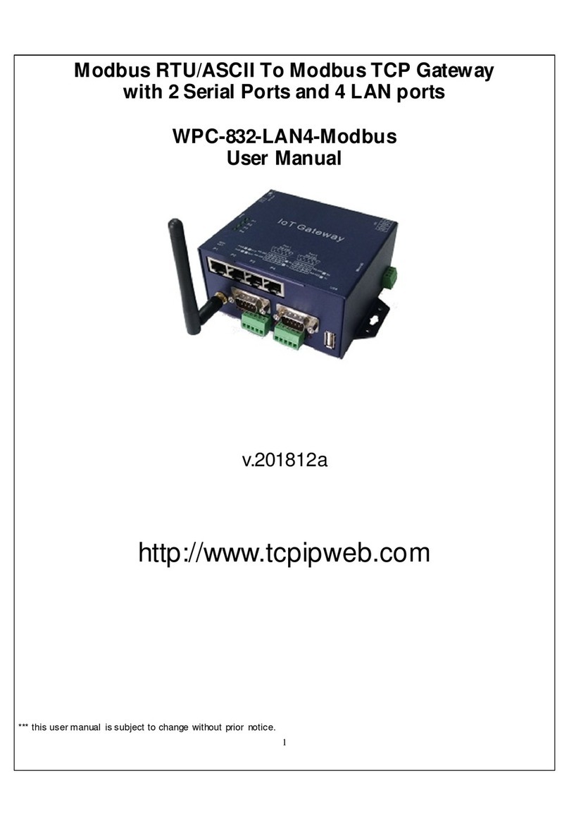
KSH International WPC-832-2-Modbus-MQTT User manual

1
WPC-832-2-Modbus-MQTT
User Manual
2 Ports Modbus TCP to Modbus RTU/ASCII
Wi-Fi, Ethernet connection
MQTT ateway
v.201901a
http://www.tcpipweb.com
*** this user manual is subject to change without prior notice.

2

3
Introduction
WPC-832-2-Modbus-MQTT RTU/ASCII to TCP Gateway provides the easy way of
connecting Modbus Serial and TCP devices to MQTT Broker via Wireless and Ethernet
LAN in Modbus TCP and RTU/ASCII networks. The wireless supports 802.11 b/g/n in
AP/Station mode with WEP/WPA/WPA2 encryption for data transmission security. The
Ethernet support 10/100 Mbps auto-detecting communication speeds. This Gateway is
designed to operate 2 Serial ports (RS-232 and RS-422/485) over wireless and Ethernet
network. This device
is a high performance design composed with carefully selecting
qualified components from reliable and certified sources. This user’s manual will
guide you to configure functions step by step.
The following topics are covered in this chapter:
Overview
Package Checklist
Product Features
Hardware Specifications

4
Overview
WPC-832-2-Modbus-MQTT 2-Port Modbus RTU/ASCII/TCP ateway support MQTT
protocol provides a perfect solution to make your industrial Sensor devices connect to
Industrial Internet of Things (IIoT) via Wireless and/or Ethernet LAN. To run with
MQTT client tools on the PC/NB or mobile devices, users can simply and effectively
publish/scribe data or command to/from remote sensors.
WPC-832-Modbus-MQTT
embedded with MT7688AN MIPS chipset makes it become
the ideal device for transmitting data from your RS-232 or RS-422/485 Serial interface
devices or remote TCP making it possible for your software to access data or control
the I/O via MQTT Broker.
Package Check List
WPC-832-2-Modbus 2-Port Modbus RTU/ASCII To Modbus TCP ateway
product
attached with the following items:
1 unit of Serial to WPC-832-Modbus ateway
1 unit of Power Adaptor (12V DC, 1A) is an option
1 unit of dipole antenna(2.0dBi)
Documentation & Utility CD
NOTE: Inform your sales representative if any of the above items missing or damaged.

5
WPC-832-2-Modbus-MQTT
Quick uide
2 Ports Modbus TCP to Modbus RTU/ASCII support MQTT
Wi-Fi, Ethernet connection
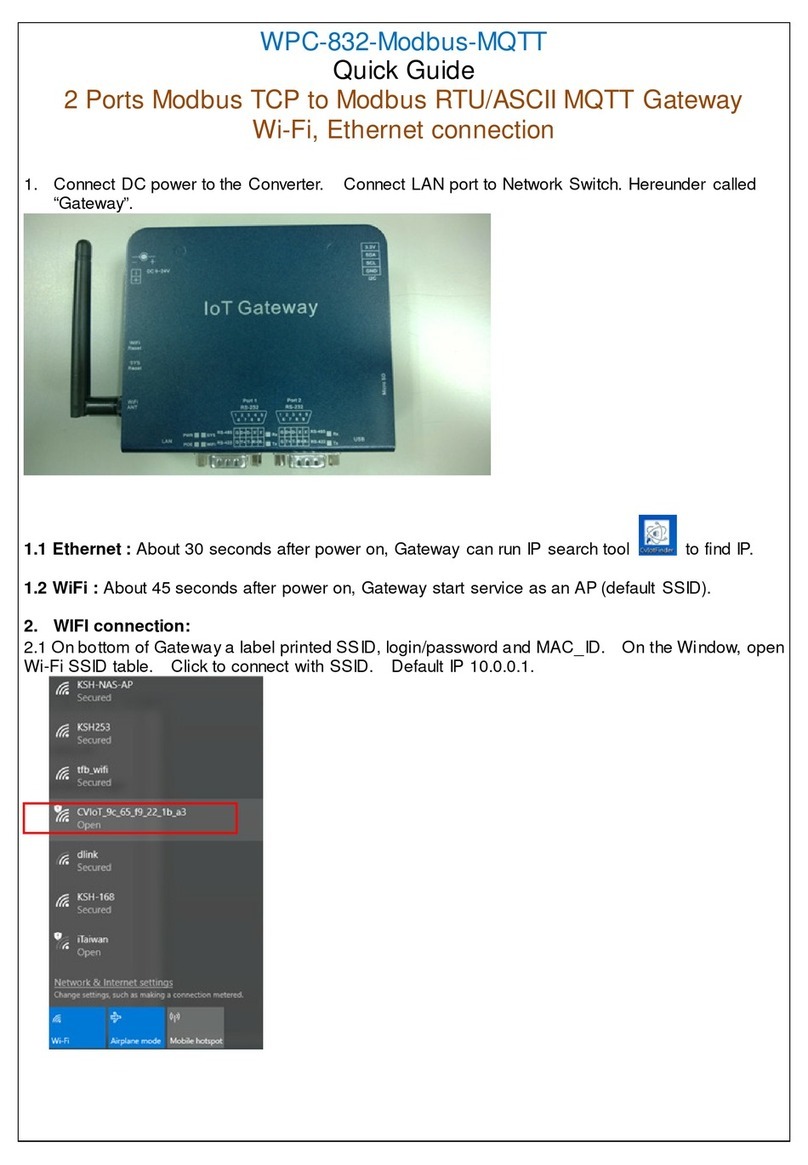
1. Connect DC power to the Converter. Connect LAN port to Network Switch. Hereunder called
“Transmitter”. Serial port RS-232 connection would require cross link cable or adaptor.
1.1 Ethernet : About 15 seconds after Transmitter power on, PC/NB can run IP search tool to
find IP.
1.2 WiFi : About 25 seconds after power on, Transmitter start service as an AP (default SSID).
2. WIFI connection:
2.1 On bottom of Transmitter a label printed SSID, login/password and MAC_ID. On the Window,
open Wi-Fi SSID table. Click to connect with SSID. Default IP 10.0.0.1.

6
3. IP search and setup:
3.1 Upon running IP search tool (CvIotFinder), if a firewall warning pop up, please click to accept
the program pass through firewall.
3.2Running CvIotFinder
Click “Find” button to search
WPC-832 on the network

7
3.3Search IP completed.
3.4Check PC or NB’s IP must be same subnet as per Transmitter then can open configuration web
page.
3.5 To change Transmitter’s IP subnet to be same as per PC/NB, clicking “Setup” button for
modification of IP, Subnet, name & description. Username and Password input is required.
Click “Setup” again to save modification.
Ethernet IP
WiFi IP

8
3.6If to change PC/NB’s IP subnet to be same as per Transmitter, modify or add new IP of PC/NB.
4. Web page Configuration:
4.1Input Login/Password: admin/admin
5. Network” page

9
5.1Wi-Fi configuration:
Go to “Wireless” section, click arrow of “Type” to select “INFRASTRUCTURE”.
5.2Go to item SSID, click “Scan” will get list of available SSID of AP, select the right one to link.
5.3Input password for the AP and assign “STATIC” and input a fixed IP address. Click “Save” when
change to other pages or “Save and Reboot”.

10
5.4For WiFi connection with Transmitter, NB/PC chooses same SSID to link. NB/PC must close
Ethernet otherwise confliction will cause connection problem in data transmission with Transmitter.
5.5Ethernet configuration:
Go to “Ethernet” section, click arrow of “Mode” to select. “STATIC” needs a fixed IP input. The
“Gateway IP” must be set with correct IP enable to connect with Internet.
6 “Serial” page
6.1To set up serial port parameters (9600,n,8,1), “Serial 1” is for “Port 1” connection, “Serial 2” is for
“Port 2” connection.

11
7. MQTT page
7.1 Client GUID: it must be the only one in all client side. This value is a default and not to be
modified.
7.2Configuration of connection with MQTT Broker.
7.2.1 Input Host IP and Socket Port number. Examle: test.mosqitto.org is a free Broker for testing
purpose only.
7.2.2 If needed, may input User Name and Password.
7.3 SSL: Enabled or Disabled.
7.4 Clean session: Enabled or Disabled.
7.4.1 When “Clean session” set “Disabled”, it will build a permanent dialog with MQTT Broker. The
dialog will keep working and save off-line message until the dialog to be cancelled due to
overtime.

12
7.4.2 When “'Clean Session” set “Enabled”,it will build a temporary dialog with MQTT Broker. The
dialog will be terminated when client break the connection with MQTT Broker.
8. TOPIC page
8.1 Section “Medias” for MQTT Client to get data from remote devices.
8.2 TOPIC settings
8.2.1 No.1 ~ 16: Transmitter can set 16 topics as publisher or subscriber for MQTT Broker.

13
8.2.2 RegName: input name of a topic. It composes with GUID as a completed topic string. For
example:『CVIoT-g7327d-9c65f91e2c27/Register/T1』, “Register” is default and similar as a
folder.
8.2.3 Protocol: RTU, ASCII, TCP for selections.
8.2.4 Media: For data sources come from 2 Serial ports (Serial 1 ~ 2) and 4 remote TCP devices
(Socket 1 ~4). .
8.2.5 Endial: Endianness
8.2.6 Slave: Input ID of Modbus Slave. Different Modbus Devices on the same “Media” must not
repeat ID.
8.2.7 REG.Start: register address.
1 – 9999 : Read/Writeable Coils (modbus function code 0x01)

14
10001-19999: Read only Coils (modbus function code 0x02)
30001-39999: Read only Registers (modbus function code 0x04)
40001-49999: Read/Writeable Registers (modbus function code 0x03)
* Please check Modbus device whether register start from 0 or 1.
8.2.8 Format: Numeric format selections
8.2.9 Count: Length of register to read out in JSON format.
8.2.10 INT(sec.): Interval time for data reading and broadcasting.
8.2.11 “Sub” is to be Subscriber. The parameters should be same as per Publisher. Publisher should
set UID/folder as same as this Transmitter.
8.2.12 Please click “Save” before change page or click “Save and Restart” to reboot Transmitter.

15
9.
Logger page
This page to show status of connection with MQTT Broker and all port connection.
10.
Data acquisition device style settings:
A style:
Protocol: select “RTU”
Media: Serial 1 or Serial 2
B style:
Protocol: select “TCP”
Media: Socket 1 ~ 4
C style:
Protocol: select “RTU”
Media: Socket 1 ~ 4
11.MQTT Topic List :
Topics Payload
Format
Note
<GUID>/Register/<RegName> JSON Format of RegName existing value

16
<GUID>/Connection/<Media> STRING Media connection status as follows:
『"disconnected"』
『"connecting"』
『"connected"』
<GUID>/Exception/<RegName> STRING Exception happened upon reading
RegName. STRING states the exception.
12.Reset (if needed)
Ensure power is on, press “WiFi Reset” button for over 25 seconds then release. Transmitter will
set configuration back to factory default. Please copy settings before reset.
Reset Button
(beneath the
antenna)
Table of contents
Other KSH International Gateway manuals
Popular Gateway manuals by other brands

ZyXEL Communications
ZyXEL Communications ZyWALL 70 quick start guide

Proxim
Proxim Skyline user guide

bihl+Wiedemann
bihl+Wiedemann 1249 user guide

HMS Networks
HMS Networks Intesis IN770AIR00 O000 Series user manual

IFM Electronic
IFM Electronic CR3146 operating instructions

Samsara
Samsara AG26 install guide